1
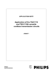
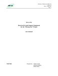
TMS320F28075PTP, TMS320F28375S, TMS320F28375D, TMS320F28377S, TMS320F28377D CPT-DFCC - DF Series Control Card Technical Brief May 2015 Manual Release 1.0 Card Version 1.0 Copyright © 2015 Creative Power Technologies P/L P.O. Box 714 MULGRAVE Victoria, 3170 Tel: +61-3-9543-8805 Fax: +61-3-9543-8802 Email: [email protected] DF SERIES CONTROL CARD TECHNICAL BRIEF DF Series Control Card Manual Revision History CARD VERSION 1.0: Initial Board for prototype purposes. Release 1.0 – Initial Release © Creative Power Technologies i RELEASE 1.0 20/05/15 DF SERIES CONTROL CARD TECHNICAL BRIEF Table of Contents 1.0 DF Series Overview...................................................................................................................... 1 1.1 DF Series Card Range .............................................................................................................. 1 1.1.1 DF Series Control Card: ................................................................................................... 1 1.1.2 DF Series Peripheral Cards ............................................................................................... 2 1.1.2.1 CPT-DFC1 .................................................................................................................... 2 1.1.2.2 CPT-DFC4 .................................................................................................................... 2 1.1.2.3 CPT-DFJ ....................................................................................................................... 2 1.1.3 DF Series Inverter Motherboard ....................................................................................... 2 1.2 DF Series Interfaces .................................................................................................................. 3 1.2.1 Main Interface ................................................................................................................... 3 1.2.2 Communications Interface ................................................................................................ 3 1.2.3 JTAG Interface ................................................................................................................. 4 2.0 Overview of the DF Series Control Card ...................................................................................... 5 2.1 DF Series Control Card Microcontroller Comparison .............................................................. 3 2.2 On-card memory ....................................................................................................................... 5 2.3 Power Supply Supervisory Circuit ........................................................................................... 5 2.4 Crystal....................................................................................................................................... 5 2.5 Digital I/O ................................................................................................................................. 5 2.6 Analog Inputs ........................................................................................................................... 5 2.7 Gate Drive Interface ................................................................................................................. 6 2.8 Communications ....................................................................................................................... 6 2.9 Power Supply............................................................................................................................ 6 2.10 JTAG/programming.................................................................................................................. 6 3.0 Specifications ............................................................................................................................... 7 3.1 MCU and Memory.................................................................................................................... 7 3.2 Analog Inputs ........................................................................................................................... 7 3.2.1 AC General Inputs ............................................................................................................ 7 3.3 Digital I/O ................................................................................................................................. 8 3.3.1 All Available Digital I/O .................................................................................................. 8 3.4 Communications Interface ........................................................................................................ 9 3.4.1 Serial Communication Interface – SCI-A ......................................................................... 9 3.4.2 Serial Communication Interface – SCI-B ......................................................................... 9 3.4.3 Serial Communication Interface – SCI-C ......................................................................... 9 3.4.4 Serial Communication Interface – SCI-D ......................................................................... 9 3.4.5 Serial Peripheral Interface – SPI-B ................................................................................. 10 3.4.6 Serial Peripheral Interface – SPI-C ................................................................................. 10 3.4.7 Enhanced Controller Area Network Module – eCAN - CAN-A .................................... 10 3.4.8 Enhanced Controller Area Network Module – eCAN - CAN-B .................................... 10 3.5 JTAG ...................................................................................................................................... 10 3.6 Software .................................................................................................................................. 11 3.7 General ................................................................................................................................... 11 3.8 Power Supply.......................................................................................................................... 11 3.9 Order Codes ............................................................................................................................ 11 Appendices ............................................................................................................................................. 12 Appendix A Component Layout ................................................................................................. 13 Appendix B Texas Instruments Technical Manuals for Control Card MCU .................................. 15 © Creative Power Technologies ii RELEASE 1.0 20/05/15 DF SERIES CONTROL CARD TECHNICAL BRIEF DF Series Concept 1.0 DF Series Overview The DF Series provides a modular, flexible integrated inverter controller platform through a range of interconnected cards. This structure provides an overall reduction in the footprint of the inverter, as well as providing a level of flexibility to support inverters rated from 1kW to 100kW+. The DF Series Control Card supports Texas Instruments PTP footprint based Piccolo and Delfino Microcontrollers (MCU). Creative Power is actively supporting a subset of these MCU variations as their feature sets are closely aligned. The latest range of MCUs support TI’s new integrated analog and control peripherals that are designed to consolidate additional functionality within the MCU. The modular nature of the DF Series system is seen through the flexible DF Series Interface which connects the DF Series Control Card to a wide range of peripheral cards. These cards include an Inverter Controller and various Communications Peripheral cards. Figure 1-1 shows the general structure of the DF Series stack, with the Control Card mounted to the Inverter Motherboard and any number of Communications Peripheral Cards mounted above. Figure 1-1: DF Series Card Stack Conceptual Overview 1.1 DF Series Card Range The following is a list of the available cards within the DF Series. Additional cards will be added to the range as they become available. 1.1.1 DF Series Control Card: The DF Series Control Card is available with the following part numbers: CPT-DF28075 (TMS320F28075PTP MCU Processor) CPT-DF28374S (TMS320F28374SPTP MCU Processor) CPT-DF28375S (TMS320F28375SPTP MCU Processor) CPT-DF28376S (TMS320F28376SPTP MCU Processor) CPT-DF28377S (TMS320F28377SPTP MCU Processor) CPT-DF28374D (TMS320F28374DPTP MCU Processor) CPT-DF28375D (TMS320F28375DPTP MCU Processor) CPT-DF28376D (TMS320F28376DPTP MCU Processor) CPT-DF28377D (TMS320F28377DPTP MCU Processor) The part number corresponding to the DF Series Control Card must be specified as part of the order. The parts in bold are CPT standard load options. The Control Card has a footprint of 96mm x 46mm (standard DF Series Footprint size). K:\CPT-DF28075\Documents\Technical\Rev 1\DF Series Control Card Technical Brief Rev 1.docx DF SERIES CONTROL CARD TECHNICAL BRIEF 1.1.2 DF Series Peripheral Cards The Peripheral Cards can be mounted within the DF Stack above the Control Card, with interconnection through either the DF Communications Interface or, for the CPT-DFJ, the DF JTAG interface. All Peripheral Cards are the standard DF Series Footprint size of 96mm x 46mm. 1.1.2.1 CPT-DFC1 CPT-DFC1 Peripheral Card provides external communications interfaces for the Control Card. It interfaces to the Control Card via the 26 way DF Communications Interface. The CPT-DFC1 Peripheral Card supports the following functionality: 1.1.2.2 Dual SCI to Isolated single USB Interface (two serial ports within the one USB connection) o USB-A: On-Card DIP Switch Selectable between SCI-A and SCI-C o USB-B: On-Card DIP Switch Selectable between SCI-B and SCI-D Isolated CAN Interface o On-Card DIP Switch Selectable between CAN-A and CAN-B Isolated SPI Interface (isoSPI configuration) o Direction Selection: On-Card DIP Switch Selectable between Master/Slave o Mode Selection: On-Card DIP Switch Selectable Phase and Offset Supporting SPI Modes 0-3 Real-Time Clock (I2C) with Supercapacitor backup CPT-DFC4 CPT-DFC4 Peripheral Card provides external communications interfaces for the Control Card. It interfaces to the Control Card via the 26 way DF Communications Interface. The CPT-DFC4 Peripheral Card supports the following functionality: 1.1.2.3 1.1.3 Isolated RS422/RS485 Interface o On-Card DIP Switch Selectable between SCI-B and SCI-D o On-Card DIP Switch Selectable between RS422 and RS485 Mode Isolated CAN Interface o On-Card DIP Switch Selectable between CAN-A and CAN-B Isolated SPI Interface (isoSPI configuration) o Direction Selection: On-Card DIP Switch Selectable between Master/Slave o Mode Selection: On-Card DIP Switch Selectable Phase and Offset – supporting SPI Modes 0-3 CPT-DFJ JTAG + SCI to Isolated single USB Interface o USB based UART Serial Port through MCU Port SCI-A o USB JTAG Emulation interface for programming and debugging of the Control Card DF Series Inverter Motherboard The CPT-DFM1 is Creative Power’s next generation high performance MCU based inverter controller motherboard. The CPT-DFM1 has been designed to provide flexibility of connection, combined with a minimum footprint for applications requiring an integrated solution to control up to a four-phase leg VSI stack. The Inverter Motherboard is compatible with the DF Series Control Cards, and the CPT-DFM1/ Control Card Platform combination contains on-card all necessary functions for a complete standalone inverter control system. The Inverter Motherboard supports up to 8 plug/solder-in gate driver modules, enabling the system to be scaled to an applications specific topology and power rating. The card has the following features: K:\CPT-DF28075\Documents\Technical\Rev 1\DF Series Control Card Technical Brief Rev 1.docx DF SERIES CONTROL CARD TECHNICAL BRIEF DF Series Main Interface Connectors 11 off Conditioned Analog Inputs (Low voltage inputs): 3 off differential AC voltage inputs, (Three-phase 4 wire input compatible) 3 off differential AC/DC voltage inputs 5 off current inputs (AC and DC compatible) Isolated Digital I/O 2 off isolated digital inputs (Field supply) 3 off MOSFET switch isolated outputs 2 off relay output, c/o contact On-Card Status Indication 1 off Power LED 4 off indication LEDs Each isolated Digital I/O has an on-card status LED 4 off DIP switches 8 off CPT-Gxx compatible gate driver interface. 3.3V TTL ePWM compatible outputs Driven by ePWM1x to ePWM4x via the DF Series Main Interface 2 sets of 4 fault feedback interrupt Supports CPT’s range of CPT-Gxx gate driver boards Switched Gate Driver Supplies to drive isolating transformers on CPT-Gxx gate driver boards Gate Driver Reset signal Quadrature Position Encoder input with Index and Strobe Push button reset On-card logic level supply generation Power supply operation from input 24VDC The CPT-DFM1 card measures 220mm x 130mm. 1.2 DF Series Interfaces The DF Series is modular in construction, which implies that signals require connection between the various cards. This is achieved using 2mm Dual-inline connectors between the cards within the DF Series Stack. The Control Card consists of three Interface types: 1.2.1 DF Series Main Interface (2 x 26-way + 3 x 20-way 2mm Dual-inline connectors) DF Series Communications Interface (26-way 2mm Dual-inline connector) DF Series JTAG Interface (10-way 2mm Dual-inline connector) Main Interface The DF Series Main Interface provides signal connection between the Control Card and Inverter Motherboard (CPT-DFM1). It is located on the underside of the Control Card. The DF Series Main Interface has been broken up into 5 separate connectors. The Analog connector is located along the left hand edge of the Control Card and Motherboard. The remaining 4 connectors contain digital signals between the Control Card to the Motherboard. Their precise functionality must be specified within the user software to suit the Motherboard. The Inverter Motherboard is configured as the base of the Main Interface Stack. The Control Card is mounted above the Inverter Motherboard. 1.2.2 Communications Interface The DF Series Communications Interface provides signal connection between the Control Card and DFC Series Peripheral Cards. The Communications Interface is located along the right hand edge of the DF Series Footprint cards. K:\CPT-DF28075\Documents\Technical\Rev 1\DF Series Control Card Technical Brief Rev 1.docx DF SERIES CONTROL CARD TECHNICAL BRIEF The Control Card is configured as the base of the Communications Interface stack. All Peripherals cards are mounted above the Control Card. 1.2.3 JTAG Interface The DF Series Control Card has a 10 way connector that interfaces to the isolated CPT-DFJ JTAG and SCI USB card. The isolated JTAG and SCI board is compatible with TI’s default JTAG software EEPROM specification and provides a fully isolated USB JTAG Interface with a Serial Communications Interface to SCI-A on the MCU. K:\CPT-DF28075\Documents\Technical\Rev 1\DF Series Control Card Technical Brief Rev 1.docx DF SERIES CONTROL CARD TECHNICAL BRIEF DF Series Control Card 2.0 Overview of the DF Series Control Card The DF Series Control Card (CPT-DFCC) is a low cost standardised MCU Control Card designed to provide a flexible interface between the TMS320F2807xPTP, TMS320F2837xS/D microcontrollers from Texas Instruments to a motherboard, such as the CPT-DFM1. The Control Card has been designed to meet different user interface requirements whilst providing a 4 layer MCU core with basic on-board functionality. The DF Series Control Card, generically referred to as the CPT-DFCC, measures 96mm x 46mm and is consistent with the DF Series Interface structure. On-card facilities include: PTP footprint compatible TMS320F2807x / TMS320F2837xS / TMS320F2837xD microcontroller Refer to Table 2-1 Supports up to 2 CPUs + 2 CLA Modules Supports up to 512k x 16 Flash (256k x 16 Flash per CPU) Supports up to 2k x 16 OTP ROM Boot ROM Software Boot Tables Supports up to 102K x 16 Single Access RAM (SARAM) made up of: 64K x 16 Global Shared RAM 18K x 16 Dedicated RAM per CPU 2 K x 16 Message RAM Serial Flash Memory with 1Mbit of non-volatile storage (SPI-A) 1 off Power LED DF Series Main Interface DF Series Communications Interface DF Series JTAG Interface Reset/Power-On Circuitry On-card regulated power supplies operating from a single +5VDC supply Figure 2-1 shows a functional block diagram of the DF Series Control Card, illustrating all major sections. K:\CPT-DF28075\Documents\Technical\Rev 1\DF Series Control Card Technical Brief Rev 1.docx DF SERIES CONTROL CARD TECHNICAL BRIEF 20-Way DF Main Interface 20-Way DF Main Interface DIGITAL HEADER 3 26-Way DF Main Interface DIGITAL HEADER 2 Power LED DIGITAL HEADER 1 MCU 176 pin PTP package DIGITAL HEADER 4 20 off 0-3.3V Analog Inputs with ‘glitch’ filtering and protective clamp 10-Way DF Series JTAG Interface 20-Way DF Main Interface ANALOG HEADER 26-Way DF Main Interface 1Mbit Flash (AT45DB011B) 26-Way DF Communications Interface Power Supply Input: +5VDC Regulated: +3.3V +1.2V Figure 2-1: Functional Diagram of DF Series Control Card © Creative Power Technologies 2 RELEASE 1.0 20/05/15 DF SERIES CONTROL CARD TECHNICAL BRIEF 2.1 DF Series Control Card Microcontroller Comparison MCU Part Name TMS320F 28075 28377D 28376D 28375D 28374D 28377S 28376S 28375S 28374S Package PTP PTP PTP PTP PTP PTP PTP PTP PTP Pins 176 176 176 176 176 176 176 176 176 1 2 2 2 2 1 1 1 1 256K 128K/CPU 86K 36K 18K/CPU 48K 2K Yes 512K 256K/CPU 102K 36K 18K/CPU 64K 2K Yes 256K 128K/CPU 86K 36K 18K/CPU 48K 2K Yes 512K 256K 512K 256K 82K 18K 66K 18K 82K 18K 66K 18K 64K Yes 48K Yes 64K Yes 48K Yes Processors 16-bit words 256K RAM (16-Bit) Dedicated 50K 18K Global Shared Message RAM 32K Yes 512K 256K/CPU 102K 36K 18K/CPU 64K 2K Yes OTP 16-bit words 2K 2K 2K 2K 2K 2K 2K 2K 2K CLA Type 1 Yes 2 (1/CPU) 2 (1/CPU) 2 (1/CPU) 2 (1/CPU) 1 1 1 1 6-Channel DMA Type 0 1 2 (1/CPU) 2 (1/CPU) 2 (1/CPU) 2 (1/CPU) 1 1 1 1 Floating Point Unit (FPU) Yes Yes Yes Yes Yes Yes Yes Yes Yes Trigonometric Math Unit Type 0 Yes Yes Yes Yes Yes Yes Yes Yes Yes VCU-II VCU-II VCU-II VCU-II VCU-II VCU-II VCU-II VCU-II 120 200 200 200 200 200 200 200 200 I/O Pins (Shared) – GPIO 97 97 97 97 97 97 97 97 97 ePWM channels 24 24 24 24 24 24 24 24 24 High-Resolution ePWM Type-4 16 16 16 16 16 16 16 16 16 eCAP Inputs Type 0 6 6 6 6 6 6 6 6 6 eQEP Modules Type 0 3 3 3 3 3 3 3 3 32 bit CPU timers 3 6 (3/CPU) 6 (3/CPU) 6 (3/CPU) 6 (3/CPU) 3 3 3 3 Watchdog Timers 1 2 (1/CPU) 2 (1/CPU) 2 (1/CPU) 2 (1/CPU) 1 1 1 1 NMI Watchdog Timer 1 2 (1/CPU) 2 (1/CPU) 2 (1/CPU) 2 (1/CPU) 1 1 1 1 Flash RAM Boom ROM Viterbi, Complex Math, CRC Unit Processor Speed (MHz) Type-4 © Creative Power Technologies 3 RELEASE 1.0 20/05/15 DF SERIES CONTROL CARD TECHNICAL BRIEF MCU Part Name TMS320F External Interrupts 28075 28377D 28376D 28375D 28374D 28377S 28376S 28375S 28374S 5 5 5 5 5 5 5 5 5 SCI Type 0 4 4 4 4 4 4 4 4 4 SPI Type 2 3 3 3 3 3 3 3 3 3 McBSP Type 1 2 2 2 2 2 2 2 2 2 USB Type 0 1 1 1 1 1 1 1 1 1 eCAN Type 0 2 2 2 2 2 2 2 2 2 0 1 1 1 1 1 1 1 1 Type 1 2 2 2 2 2 2 2 2 2 MSPS 3.1 3.5 3.5 3.5 3.5 3.5 3.5 3.5 3.5 3 4 4 4 4 4 4 4 4 325ns 290ns 290ns 290ns 290ns 290ns 290ns 290ns 290ns Bits 12 12 12 12 12 12 12 12 12 Pins 17 20 20 20 20 20 20 20 20 Channels 17 9 / 20 9 / 20 9 / 20 9 / 20 9 / 20 9 / 20 9 / 20 9 / 20 1.1 1.1 1.1 1.1 4 4 4 4 290ns 290ns 290ns 290ns Bits 16 16 16 16 Pins 20 20 20 20 20 20 20 9 (diff) 9 (diff) 9 (diff) 9 (diff) 9 (diff) 9 (diff) 9 uPP I2C Modules Conversion time 12 bit ADC MSPS Modules Conversion time 16 bit ADC Channels CMPSS - integrated DACs 8 8 8 8 8 8 8 8 8 Buffered DAC 3 3 3 3 3 3 3 3 3 Sigma-Delta Filter Module channels 8 8 8 8 8 8 8 8 8 3.3V/1.2V 3.3V/1.2V 3.3V/1.2V 3.3V/1.2V 3.3V/1.2V 3.3V/1.2V 3.3V/1.2V 3.3V/1.2V 3.3V/1.2V Supply Voltage Table 2-1: Microcontroller Comparison for the DF Series Control Cards © Creative Power Technologies 4 RELEASE 1.0 20/05/15 DF SERIES CONTROL CARD TECHNICAL BRIEF 2.2 On-card memory The CPT-DFCC supports a range of Texas Instruments microcontrollers. When used with the TMS320F28377D, the CPT-DF28377D Control Card supports up to 512k x 16bit of on-card Flash (256k x 16bit per MCU), 102k x 16bit of RAM, a Boot ROM and a 2k x 16bit OTP. Programs can be directly executed from RAM, via the JTAG interface or from Flash. By default, the card executes programs from internal RAM, although there are on-card solderable links that enable selection of the active boot mode from the other available sources. In addition to the MCU on-chip memory, the DF Series Control Card has a 1Mbit SPI interfaced Flash Memory chip for external data storage. This chip can be upgraded to 16Mbit in the same footprint. 2.3 Power Supply Supervisory Circuit The Control Card contains a Supervisory Circuit IC that continuously monitors each of the regulated MCU supplies (+3.3V and +1.2V). The RESET* line is asserted if either of the voltages drops below the threshold limit. During power-on, the RESET* line is asserted until the regulated supplies exceed the threshold limits. The RESET* line is available on the DF Series Main and Communications Interfaces, which enables both the Supervisory Circuit and the MCU to trigger off-card peripheral resets. An off-card reset generated via the Main Interface is fed to the Supervisory Circuit IC to enable a controlled MCU RESET*. 2.4 Crystal The default crystal package on the DF Series Control Card is a TXC Corporation 7B-20.000MEEQ-T. This same 20MHz crystal is supported by all of the microcontrollers within the Control Card range. 2.5 Digital I/O The DF Series Control Card supports a maximum of 85 bits of 3.3V-TTL digital I/O, depending on the user defined configuration of specific MCU pins. All pins are supplied non-buffered to the connector interfaces. The DF Series Main Interface Digital Headers have a total of 64 bits spread across 4 connectors, the Communications Interface Header has 19 bits, and the DF Series JTAG Header has 2 bits. The header allocation of the digital I/O bits supports their operation in “Peripheral I/O” mode. All digital I/O pins on the Control Card MCU have the capability to operate in either “Digital I/O or “Peripheral I/O” mode. The user must select the correct mode of operation for each pin within their software. For a detailed description of the Peripheral Modes refer to the Technical User Manual for the selected MCU. Details of the appropriate documents, as well as links are provided in Appendix B. 2.6 Analog Inputs The DF Series Control Card MCU has 20 (17 for the DF28075) off ADC inputs that accept voltages in the range of 0 – 3 (3.3) Volts. The analog inputs are divided into four Modules (ADCA, ADCB, ADCC and ADCD). Each Module has an 8 to 1 analog multiplexer with its own sample and hold circuit. The sample and hold circuit output is fed into the modules 12-bit ADC. The maximum total conversion time for each ADC input is 290ns (325ns for the DF28075). The 17 off filtered analog inputs are available on the 26-way DF Series Main Interface Analog Header. They each have a low pass (RC) or “glitch” filter and a diode clamp circuit on-card the signals are fed into the MCU. Note that the default configuration of the Control Card has these RC “glitch” filters loaded with 100R and 2.2nF. The board accepts Analog Input voltages in the range of 0 –3.3V, with the diode clamps ensuring excessive voltage does not get presented to the MCU pins. © Creative Power Technologies 5 RELEASE 1.0 20/05/15 DF SERIES CONTROL CARD TECHNICAL BRIEF For a detailed description of the ADC Module refer to the Technical User Manual for the selected MCU. Details of the appropriate documents, as well as links are provided in Appendix B. 2.7 Gate Drive Interface The Control Card MCU supports up to 24 ePWM Module outputs through the DF Series Main Interface Digital Headers 2 and 3. For a detailed description of the ePWM Module refer to the Technical User Manual for the selected MCU. Details of the appropriate documents, as well as links are provided in Appendix B. 2.8 Communications The Control Card MCU can be configured to support many different communications protocols. The functional allocation of these peripherals to specific pins is user selectable as part of the MCU initialisation. The MCU supports the following communications interfaces: 4 Serial Communications Interfaces (SCI) 3 Serial Peripheral Interfaces (SPI) 2 I2C Interfaces (I2C) 2 CAN-Bus Ports (eCAN) JTAG Emulation The DF Series Communications Interface is a consolidated header for providing a subset of the available communications signals to the DFC Peripheral Cards. This interface can be configured for the following 4 Serial Communications Interfaces (SCI-A, SCI-B, SCI-C, SCI-D) 1 Serial Peripheral Interface (SPI-B) 1 I2C Interfaces (SDA) 2 CAN-Bus Ports (CAN-A, CAN-B) The JTAG Emulation and 2 SCI-A supported GPIO pins are available on the DF Series JTAG Interface header. 2.9 Power Supply The standard CPT-DF28377 controller board has an on-card voltage regulator chip that produces a regulated +3.3V and +1.2V from the +5V input on the DF Series Main Interface Digital Header 1. The +3.3V and +1.2V supplies have additional LC filters before they are fed to the MCU to reduce noise injection. In addition the +3.3V also supplies Analog and Oscillator voltages via LC filters. 2.10 JTAG/programming The Control Card can be programmed via the JTAG interface using a CPT-DFJ JTAG to USB interface card. The CPT-DFJ has an isolated JTAG/SCI to USB interface for programming the MCU’s Flash ROM or RAM. This port can also be used for emulator/debugging purposes. © Creative Power Technologies 6 RELEASE 1.0 20/05/15 DF SERIES CONTROL CARD TECHNICAL BRIEF 3.0 3.1 Specifications MCU and Memory Microcontroller The CPT-DFCC supports a range of Texas Instruments PTP Footprint Microcontrollers. The supported MCUs are listed in Section 2.1 of this manual. Non-Volatile Memory Storage 1Mbit of memory storage using an SPI flash ROM chip Accessed via SPI-A interface on MCU 3.2 Analog Inputs Number of Channels 20 single ended (17 on TMS320F28075) A/D Resolution 12 bits A/D Conversion Time 290ns (325ns on TMS320F28075) Number of ADC Modules 4 Number of S/H units 4 (1 per Module) 3.2.1 AC General Inputs Definition 20 (17) off 0 –3.3V analog inputs with low pass filter capacitors ADC-A0, ADC-A1, ADC-A2, ADC-A4, ADC-B0, ADC-B1, ADC-B2, ADC-B3 ADC-C2, ADC-C3, ADC-C4 (not available on TMS320F2807x) ADC-D0, ADC-D1, ADC-D2, ADC-D3, ADC-D4 ADCIN-14, ADCIN-15 Input Voltage Range 0 –3.3V maximum Dynamic Response Cut-off frequency >150kHz Default loaded values for all channels are R = 100 Ω and C = 2.2nF PCB Connections 26-way DF Series Main Interface Analog Header (X5) © Creative Power Technologies 7 RELEASE 1.0 20/05/15 DF SERIES CONTROL CARD TECHNICAL BRIEF 3.3 Digital I/O 3.3.1 All Available Digital I/O Definition 85 bits total GPIO0-27 GPIO28-29 (SCI-A port configurable with CPT-DFJ operation) GPIO30-35 GPIO36-37 (shared with eCAN-A bus configurable with CPT-DFC operation) GPIO38-39 (shared with eCAN-B bus configurable with CPT-DFC operation) GPIO40-41 GPIO42-43 (shared with I2C Port A configurable with CPT-DFC operation) GPIO44-45 GPIO46-47 (shared with SCI-D port) GPIO48-49 (shared with SCI-A port configurable with CPT-DFC operation) GPIO50-53 (shared with EQEP1 port configurable on DF Series Main Interface) GPIO54-57 (shared with SCI-B and SCI-C ports configurable with CPT-DFC operation) GPIO63-66 (shared with SPI-B port configurable with CPT-DFC operation) GPIO67-72 GPIO73 (shared with XCLKOUT) GPIO74-81 GPIO84-92 Digital high input voltage threshold 2.0V Digital low input voltage threshold 0.8V Digital outputs rated at ±4mA per bit, ABSOLUTE MAXIMUM PCB Connection 26-way DF Series Main Interface: Digital Header 1 (X1) GPIO67-GPIO72, GPIO74-81, GPIO84-87 20-way DF Series Main Interface: Digital Header 2 (X2) GPIO0-7, GPIO10-13, GPIO 88-92 20-way DF Series Main Interface: Digital Header 3 (X3) GPIO8-9, GPIO14-27 20-way DF Series Main Interface: Digital Header 4 (X4) GPIO30-35, GPIO40-41, GPIO44-45, GPIO50-53 26-way DF Series Communications Interface Header (X6) GPIO36-39, GPIO42-43, GPIO48-49, GPIO54-57, GPIO63-66, GPIO73 10-way DF Series JTAG Interface Header (X7) GPIO28-29 © Creative Power Technologies 8 RELEASE 1.0 20/05/15 DF SERIES CONTROL CARD TECHNICAL BRIEF 3.4 Communications Interface Definition The Control Card has four off serial communications interface ports (SCI-A, SCIB, SCI-C and SCI-D), three off serial peripheral interfaces (SPI-A, SPI-B and SPI-C), two enhanced controller area network port (CAN-A, CAN-B) and two I2C Ports Configuration DEFAULT: All SCI, SPI, CAN and I2C ports are Digital I/O Isolation None 3.4.1 Serial Communication Interface – SCI-A Definition Two-wire asynchronous serial port (UART) that supports a 16-level, receive and transmit FIFO for reducing servicing overhead. The receiver and transmitter are double buffered with separate enable and interrupt bits DEFAULT MODE: Digital I/O Communications Port SCI-A Signals SCITXDA, SCIRXDA Alternative Configuration Options GPIO48-49 – 26-way DF Series Communications Interface Header (X6) GPIO29-28 – 10-way DF Series JTAG Interface Header (X7) GPIO42-43 – 26-way DF Series Communications Interface Header (X6) 3.4.2 Serial Communication Interface – SCI-B Definition Two-wire asynchronous serial port (UART) that supports a 16-level, receive and transmit FIFO for reducing servicing overhead. The receiver and transmitter are double buffered with separate enable and interrupt bits DEFAULT MODE: Digital I/O Communications Port SCI-B Signals SCITXDB, SCIRXDB Preferred Configuration GPIO54-55 – 26-way DF Series Communications Interface Header (X6) 3.4.3 Serial Communication Interface – SCI-C Definition Two-wire asynchronous serial port (UART) that supports a 16-level, receive and transmit FIFO for reducing servicing overhead. The receiver and transmitter are double buffered with separate enable and interrupt bits DEFAULT MODE: Digital I/O Communications Port SCI-C Signals SCITXDC, SCIRXDC Preferred Configuration GPIO56-57 – 26-way DF Series Communications Interface Header (X6) 3.4.4 Serial Communication Interface – SCI-D Definition Two-wire asynchronous serial port (UART) that supports a 16-level, receive and transmit FIFO for reducing servicing overhead. The receiver and transmitter are double buffered with separate enable and interrupt bits DEFAULT MODE: Digital I/O Communications Port SCI-D Signals SCITXDD, SCIRXDD Preferred Configuration GPIO46-47 – 26-way DF Series Communications Interface Header (X6) © Creative Power Technologies 9 RELEASE 1.0 20/05/15 DF SERIES CONTROL CARD TECHNICAL BRIEF Serial Peripheral Interface – SPI-B 3.4.5 Definition Four-pin serial peripheral interface (SPI) module. It is a high speed, synchronous serial I/O port that allows a serial bit stream of programmed length (one to sixteen bits) to be shifted into and out of the device at a programmable bit-transfer rate DEFAULT MODE: Configured as digital I/O pins Compatibility 4 wire SPI mode Signals SPISIMOB, SPISOMIB, SPICLKB, SPISTEB* Preferred Configuration GPIO63-66 – 26-way DF Series Communications Interface Header (X6) Serial Peripheral Interface – SPI-C 3.4.6 Definition Four-pin serial peripheral interface (SPI) module. It is a high speed, synchronous serial I/O port that allows a serial bit stream of programmed length (one to sixteen bits) to be shifted into and out of the device at a programmable bit-transfer rate DEFAULT MODE: Configured as digital I/O pins Compatibility 4 wire SPI mode Signals SPISIMOC, SPISOMIC, SPICLKC, SPISTEC* Preferred Configuration GPIO69-72 – 26-way DF Series Main Interface: Digital Header 1 (X6) Enhanced Controller Area Network Module – eCAN - CAN-A 3.4.7 Definition CAN bus module which supports up to 1Mbps transfer DEFAULT MODE: Configured as digital I/O pins Compatibility Fully compatible with CAN protocol version 2.0B Signals CANRXA, CANTXA Preferred Configuration GPIO36-37 – 26-way DF Series Communications Interface Header (X6) Enhanced Controller Area Network Module – eCAN - CAN-B 3.4.8 Definition CAN bus module which supports up to 1Mbps transfer DEFAULT MODE: Configured as digital I/O pins Compatibility Fully compatible with CAN protocol version 2.0B Signals CANRXB, CANTXB Preferred Configuration GPIO38-39 – 26-way DF Series Communications Interface Header (X6) 3.5 JTAG Definition MCU programming interface, which enables the MCU to interface the real-time debugging environment Compatibility Compatible with IEEE 1149.1 standard for scan-based emulation Configuration 3.3V-TTL Level signals Connector compatible with the CPT-DFJ Isolated JTAG/SCI card. PCB Connection 26-way DF Series JTAG Interface Header (X7) © Creative Power Technologies 10 RELEASE 1.0 20/05/15 DF SERIES CONTROL CARD TECHNICAL BRIEF 3.6 Software Support Software (Available Separately) 3.7 Standard library source code, sample programs Texas Instruments: Code Composer Studio V5.5 and above compatible General L: 96mm Physical Dimensions W: 46mm H: 11mm approx. Mounting Arrangement 4 off 3.5 mm holes located in the corners of the card 88mm x 38mm hole centres. DF Series Main Interface can be soldered to the motherboard for practical installations Environmental -40 – 85°C ambient operating temperature 5% - 95% non-condensing humidity 3.8 Power Supply Input Voltage Range 5VDC (4.8V – 6V) Standalone Input Current 100-250mA (depending on the active sections within the MCU) Max Input Power Approx. TBD ~500mW Supplies Generated on-card +3.3V Digital +1.2V MCU Supply Input Power Connector 26-way DF Series Main Interface: Digital Header 1 (X1) +5V on pins 1,3,5 and GND on pins 2, 4, 6 Output Power Connections 20-way DF Series Main Interface: Digital Header (X4) +3.3V on pin 17, 20 10-way DF Series JTAG Interface (X7) +3.3V on pin 9 26-way DF Series Communications Interface (X6) +5V on pins 23, 25 and +3.3V on pin 21, 22 3.9 Order Codes CPT-DF28075 DF Series Control Card with TMS320F28075PTP CPT-DF28374S DF Series Control Card with TMS320F28374SPTP CPT-DF28375S DF Series Control Card with TMS320F28375SPTP CPT-DF28376S DF Series Control Card with TMS320F28376SPTP CPT-DF28377S DF Series Control Card with TMS320F28377DPTP CPT-DF28374D DF Series Control Card with TMS320F28374DPTP CPT-DF28375D DF Series Control Card with TMS320F28375DPTP CPT-DF28376D DF Series Control Card with TMS320F28376DPTP CPT-DF28377D DF Series Control Card with TMS320F28377DPTP © Creative Power Technologies 11 RELEASE 1.0 20/05/15 DF SERIES CONTROL CARD TECHNICAL BRIEF Appendices © Creative Power Technologies 12 RELEASE 1.0 20/05/15 DF SERIES CONTROL CARD TECHNICAL BRIEF Appendix A Component Layout Top Layer © Creative Power Technologies 13 RELEASE 1.0 20/05/15 DF SERIES CONTROL CARD TECHNICAL BRIEF Bottom Layer © Creative Power Technologies 14 RELEASE 1.0 20/05/15 DF SERIES CONTROL CARD TECHNICAL BRIEF Appendix B Texas Instruments Technical Manuals for Control Card MCU TMS320F28075PTP Piccolo Microcontroller Texas Instruments Website: http://www.ti.com/product/TMS320F28075/technicaldocuments Datasheet Document Number: Technical Manual Document Number: SPRS902 SPRUHM9 TMS320F2837xSPTP Texas Instruments Website: http://www.ti.com/product/TMS320F28377S/technicaldocuments Datasheet Document Number: Technical Manual Document Number: SPRS881 SPRUHX5 TMS320F2837xDPTP Texas Instruments Website: http://www.ti.com/product/TMS320F28377D/technicaldocuments Datasheet Document Number: Technical Manual Document Number: © Creative Power Technologies SPRS880C SPRUHM8C 15 RELEASE 1.0 20/05/15