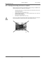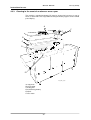
1
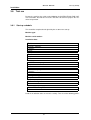
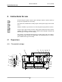
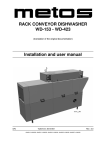
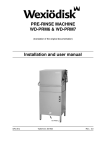
RACK CONVEYOR DISHWASHER
WD-151E - WD-421E
(translation of the original documentation)
Installation and user manual
S/N:
Valid from: 01.10.2012
Rev.: 3.0
WD-151E - WD-421E
Rev.
1. General information ......................................................................... 1
1.1 Symbols used in this manual ........................................................................... 1
1.2 Symbols on the dishwasher ............................................................................. 2
1.2.1 Machine marking ...................................................................................... 2
1.3 Checking that the machine and the manual correspond .................................. 2
2. Safety instructions ........................................................................... 3
2.1 General information ......................................................................................... 3
2.2 Transport .......................................................................................................... 3
2.3 Installation ........................................................................................................ 3
2.4 Detergent and drying agent ............................................................................. 4
2.5 Operation ......................................................................................................... 4
2.5.1 Crushing risk ............................................................................................. 4
2.5.2 Risk of slipping .......................................................................................... 4
2.6 Cleaning ...........................................................................................................
2.6.1 Pressure washing .....................................................................................
2.6.2 The outside of the machine ......................................................................
2.6.3 Cleaning the floor ......................................................................................
2.7 Repairing and servicing the dishwasher ..........................................................
2.7.1 Safety instructions if the machine is not functioning .................................
2.8 Recycling the machine .....................................................................................
4
4
4
5
5
5
5
3. Installation ........................................................................................ 6
3.1 General information .........................................................................................
3.2 Requirements for the installation site ...............................................................
3.2.1 Lighting .....................................................................................................
3.2.2 Ventilation .................................................................................................
3.2.3 Drains .......................................................................................................
3.2.4 Space for servicing ...................................................................................
3.3 Transport and storage ......................................................................................
3.4 Unpacking ........................................................................................................
3.5 Recycling the packaging ..................................................................................
3.6 Installation ........................................................................................................
3.6.1 Positioning the machine ............................................................................
6
6
6
6
6
6
7
7
7
8
9
WD-151E - WD-421E
Rev.
3.7 Connections ................................................................................................... 10
3.7.1 Electrical connection ...............................................................................
3.7.2 Water connection ....................................................................................
3.7.3 Steam connection (option) ......................................................................
3.7.4 Drain connection .....................................................................................
3.7.5 Ventilation ...............................................................................................
3.7.6 Installing extra equipment .......................................................................
3.7.7 Setting the flows .....................................................................................
11
11
11
12
12
12
13
3.8 Installing detergent and drying agent equipment ...........................................
3.8.1 Electrical connection of the equipment ...................................................
3.8.2 Detergent dosing system ........................................................................
3.8.3 Drying agent dosing system ...................................................................
15
16
16
18
3.9 Trial run .......................................................................................................... 19
3.9.1 Start-up schedule .................................................................................... 19
3.10 Technical documentation ............................................................................. 21
4. Instructions for use ........................................................................ 22
4.1 Preparations ...................................................................................................
4.1.1 The machine's design .............................................................................
4.1.2 Preparations before filling .......................................................................
4.1.3 Filling and heating the machine ..............................................................
4.1.4 Filing and heating the machine using timer start (option) .......................
4.2 Using the machine .........................................................................................
4.2.1 Washing ..................................................................................................
4.2.2 Guaranteed final rinse ............................................................................
4.2.3 Emergency stop ......................................................................................
4.2.4 Changing the water .................................................................................
22
22
23
24
24
26
26
27
27
27
4.3 After use – cleaning .......................................................................................
4.3.1 Daily cleaning .........................................................................................
4.3.2 Cleaning and checking each week or as required ..................................
4.3.3 Cleaning in the event of an alarm or once a year ...................................
4.3.4 Operating problems ................................................................................
28
28
31
32
34
5. Technical information .................................................................... 38
WD-151E - WD-421E
Rev. 3,0 (201210)
General information
1. General information
Read the instructions in this manual carefully as they contain important information regarding the correct, effective and safe installation, use and servicing of the
dishwasher.
Keep this manual in a safe place so that it can be used by other operators of the
dishwasher.
The electronics in the machine are RoHS compatible.
1.1
Symbols used in this manual
This symbol warns of situations where a safety risk may arise. The instructions
given should be followed in order to prevent injury.
This symbol on a component is a warning of electrical equipment. The machine
is sensitive to electrostatic discharge (ESD), which is why a static electricity wristband must be used when handling the electronics.
This symbol explains the correct way to perform a task in order to prevent poor
results, damage to the dishwasher or hazardous situations.
This symbol identifies recommendations and hints to help you to get the best performance from the machine.
This symbol explains the importance of careful and regular cleaning of the machine to meet hygiene requirements.
1
WD-151E - WD-421E
Rev. 3,0 (201210)
General information
1.2
Symbols on the dishwasher
This symbol on a component is a warning of electrical equipment. The component
may only be removed by a qualified electrician. The machine is sensitive to electrostatic discharge (ESD), which is why a static electricity wristband must be used
when handling the electronics.
1.2.1
Machine marking
The machine has two rating plates, one of which is placed at the bottom of one
side of the machine and the other in the electrical cabinet. The technical information on the plates is also included on the machine's wiring diagram. The various
rating fields show:
Type
1
S/N:
2
5 V
6
M
9 kW
3
7 Hz
10 kW
IP 4
8 A
11 kW
Mårdvägen 4, S-352 45 V ÄXJÖ SWEDEN
1.
2.
3.
4.
5.
6.
7.
8.
9.
10.
11.
1.3
marks_SAP
Machine type
Machine serial number
Year of manufacture
Enclosure protection class
Voltage
Number of phases with or without zero
Frequency
Main fuse
Motor output
Electrical heat output
Max. output
Checking that the machine and the manual correspond
Check that the type description on the rating plate corresponds with the type description on the front of the manual. If manuals are missing, it is possible to order
new ones from the manufacturer or the local distributor. When ordering new manuals, it is important to quote the machine number found on the rating plates.
2
WD-151E - WD-421E
Rev. 3,0 (201210)
Safety instructions
2. Safety instructions
2.1
General information
The machine is CE marked, which means that it complies with the requirements
of the EU machinery directive with regard to product safety. Product safety means
that the design of the machine will prevent personal injury or damage to property.
Modifying the equipment without the approval of the manufacturer invalidates the
manufacturer’s product liability.
To further improve safety during installation, operation and servicing, the operator
and the personnel responsible for installing and servicing the machine should
read the safety instructions carefully.
Switch off the machine immediately in the event of a fault or malfunction. The machine must only be serviced by trained engineers. The regular checks described
in the manual must be carried out in accordance with the instructions. The machine must be serviced by a person authorised to do so by the manufacturer. Use
original spare parts. Contact an authorised service company to draw up a programme of preventative maintenance. Dangerous situations may arise if the instructions above are not followed.
Before using the machine, ensure that personnel are given the necessary training
in operating and maintaining the machine.
2.2
Transport
Handle the machine with care during unloading and transport to avoid the risk of
it tipping over. Never lift or move the machine without using the wooden packaging to support the stand.
2.3
Installation
This symbol on a component is a warning of electrical equipment. The machine
is sensitive to electrostatic discharge (ESD), which is why a static electricity wristband must be used when handling the electronics.
Water and steam pipes must only be connected by authorised personnel.
Water pipes must be connected in a way that complies with the current regulations of the local water supply authority. Check that the water and steam connections are tight before operating the machine.
Make sure that the mains voltage is the same as that indicated on the machine's
rating plate.
3
WD-151E - WD-421E
Rev. 3,0 (201210)
Safety instructions
2.4
Detergent and drying agent
Only detergent and drying agent intended for industrial dishwashing machines
must be used. NOTE! Washing-up liquid must not be used in the machine or for
pre-treating items (soaking, pre-washing, etc.). Contact your detergent supplier
regarding the choice of a suitable detergent.
Be aware of the risk of handling washing and drying agents. Protective gloves and
safety glasses should be used when handling dishwasher detergent. Read the
warning text on the detergent and drying agent containers as well as the detergent supplier's regulations.
2.5
2.5.1
Operation
Crushing risk
The reciprocating action of the feeding cradle might cause injuries at the in- and
outfeed ends of the machine and also in the scullery equipment such as corner
feeding, moving straight parts and conveyor bends connected to the machine.
2.5.2
Risk of slipping
Keep the floor dry to eliminate any risk of slipping. Mop up any water which has
been spilled.
2.6
Cleaning
The temperature of the water in the tank is approx. 60°C and contains detergent.
Be careful when draining and cleaning the tank. Use protective gloves.
2.6.1
Pressure washing
The machine must not be cleaned with a pressure washer. If pressurised water is
directed at the electrical cabinet, the water may penetrate the cabinet and damage the electrical equipment, which may affect the safety of the machine.
In order to satisfy current requirements, electrical components of approved enclosure classes are used. There is no enclosure class capable of withstanding high
pressure.
2.6.2
The outside of the machine
Pressure washers and hoses must not be used to wash the outside of the machine. Water can penetrate into the electrical cabinet and the control panel and
damage the equipment, which may affect the safety of the machine.
4
WD-151E - WD-421E
Rev. 3,0 (201210)
Safety instructions
2.6.3
Cleaning the floor
When the floor is being cleaned using a pressure washer, water can splash up
under the machine and damage the components. These have not been designed
to withstand being washed with water. Never use a pressure washer to clean the
floor within 1 metre of the dishwasher without the special protective covers that
are available to prevent splashing. Problems with splashing can also occur when
using ordinary hoses.
2.7
Repairing and servicing the dishwasher
Disconnect the power supply before removing the front panel. Avoid touching hot
pipes and the booster heater.
2.7.1
Safety instructions if the machine is not functioning
Check the following:
•
•
•
•
•
Does the display show any error messages?
Has the machine been used according to the instructions?
Are all the removable parts in the correct place?
Is the mains switch in the ON position?
Are the fuses in the electrical cabinet undamaged? Ask the service personnel to check the fuses.
If this does not solve the problem, ask authorised service personnel to check the
machine.
2.8
Recycling the machine
When the dishwasher has reached the end of its service life, it must be recycled
in accordance with current regulations. Contact professionals who specialise in
recycling.
5
WD-151E - WD-421E
Rev. 3,0 (201210)
Installation
3. Installation
3.1
General information
The machine must be installed by authorised personnel only.
Read these instructions carefully, as they contain important information regarding
the correct installation method.
The instructions should be used together with the machine’s wiring diagram and
flow diagrams for water and steam.
The machine is CE marked. The CE mark is only valid for machines that have not
been modified. If the machine is damaged as a result of the instructions not being
followed, this invalidates the supplier's guarantee and the product liability.
3.2
3.2.1
Requirements for the installation site
Lighting
In order to ensure the best possible working conditions during installation, operation, servicing and maintenance, make sure that the machine is installed in a welllit room.
3.2.2
Ventilation
The machine produces heat and steam when in operation. In order to ensure the
best possible working conditions, a certain air change rate is required in the dishwashing room. The ventilation requirements for the room are dimensioned as per
applicable standars.
3.2.3
Drains
There must be a floor drain with an effective trap for the machine's waste water
and for water used for cleaning. The drain should be located under the machine's
loading bench. The floor drain capacity can be found in the TECHNICAL SPECIFICATIONS.
3.2.4
Space for servicing
A 1-metre area should be left clear in front of the machine for servicing purposes.
The area above the machine must not contain any equipment which could prevent the fitting, servicing and replacement of parts.
6
WD-151E - WD-421E
Rev. 3,0 (201210)
Installation
3.3
Transport and storage
Always transport the machine in an upright position.
Take care during transport, as there is a risk of the equipment tipping over.
NOTE: The machine must not be transported without a pallet or other support,
Some form of support beam must always be used along the sides of the machine
during transport. otherwise the machine may become damaged. When transporting the machine without a normal wooden pallet, always check that none of the
components underneath the machine can be damaged.
If the machine is not being installed immediately, it must be stored in a frost-free
area where the air is dry.
3.4
Unpacking
Check against the delivery note that all the units have been delivered.
Inspect the machine for any transport damage.
3.5
Recycling the packaging
Packaging must be disposed of or recycled in accordance with local regulations.
7
WD-151E - WD-421E
Rev. 3,0 (201210)
Installation
3.6
Installation
1
13
14
16
2
3
15
10 11
1
9
10 11
5 6
4
4
12
A
B
C
D
E
10 11
8
4
12
6
5
E_03_R2
9
1.
2.
3.
4.
5.
6.
7.
8.
9.
10.
11.
12.
13.
14.
15.
16.
1
Electrical connection
Cold water connection/filter
Hot water connection/filter
Drain connection
Steam connection
Condensation connection
Floor drain
Condensing battery exhaust fan
Alternative electrical connection
Alternative cold water connection
Alternative hot water connection
Alternative drain connection
Non-return valve
Vacuum valve
Detergent dosage outlet
Main switch
8
7
WD-151E - WD-421E
Rev. 3,0 (201210)
Installation
WD-151E
A
B
C
D
E*
WD-211E
1230
1535
1655
1830
2135
2255
WD-241E
WD-331E
WD-421E
2130
2435
2555
1360
1670
3030
3335
3455
2260
1670
3930
4235
4355
* = Installation dimensions at bench height
Check that the overheating protection on the booster heater and the tank element
are set to zero.
3.6.1
Positioning the machine
Remove the protective plastic on the sides which will be put against the wall.
The distance to the wall should be 15-30 mm.
Put the machine in position and check that it is horizontal using a spirit level. Adjust the height using the machine's legs.
c
a
a
a
b
CEIT_plac_R1
The machine must be evenly balanced and checked on three sides:
•
•
•
On the cover edge of the front (a) (tank body).
On the cover edge of the infeed (b).
On the cover edge of the outfeed (c).
Once the machine has been filled with water, check that it is level. Close the doors
and check that the tops of the doors are in a straight line. Adjust the machine using the legs.
9
WD-151E - WD-421E
Rev. 3,0 (201210)
Installation
3.7
Connections
13 14 15
16
18
1
2
8
9
3
4
5
6
7
10
11
12
17
25
24
23
19
B
A
B
22 21 20 A
E_02_R1
Installation of the machine (the picture shows the WD-241E)
A=Drain connection
B=Hole in the end plate for the waste pipe
1.
2.
3.
4.
5.
6.
7.
8.
9.
10.
11.
12.
13.
14.
15.
16.
17.
18.
19.
20.
21.
22.
23.
24.
25.
Display
LEDs which indicate that functions are enabled
Button for automatic operation
Button for manual operation
Button to the feed
Button for the diagnostics function.
Button for diagnostic messages
LED for indication of alarms
LED which lights when the power is switched on
Button for resetting alarm
On/Off
Emergency stop
Electrical connection
Main switch
Electrical cabinet
Cold water connection 5-12°C
Hot water connection 55-70°C
Solenoid valve box
Photocell for wash start
Alternative hot water connection (option)
Alternative cold water connection (option)
Drain connection, diameter 50mm.
Steam connection (option)
Condensation connection (option)
Impulse arm for final rinse
Alternative electrical connection from floor
10
WD-151E - WD-421E
Rev. 3,0 (201210)
Installation
3.7.1
Electrical connection
This symbol on a component is a warning of electrical equipment. The part may
only be removed by a qualified electrician or trained personnel.
Information about electrical connections can be found on the machine's wiring diagrams. The wiring diagrams are shown on the inside of the electrical cabinet
door. Store the diagrams in the electrical cabinet after installation.
The machine has a built-in main switch (14). Connect the electric cable at (13).
NOTE: In special cases certain dishwashers may have an electrical connection
from the floor. The cable is then drawn behind the cover plate at (25).
Check the direction of rotation of the pump motors during operation when the
tanks are full of water. The direction of rotation must conform without exception
to the direction of the arrow on the pump. Stop the dishwasher immediately if the
direction of rotation is incorrect and change two of the incoming phases.
An earth cable for potential equalisation is connected to the earth bolt on the
stand. The connection is located on the beam by the final rinse zone and fitted
with the following rating plate:
Rating plate for earth bolt
After completing the electrical installation, switch on the main switch and all circuit
breakers.
3.7.2
Water connection
Connect the cold and hot water pipes according to the labels by the connection
points (20,21). If the machine is connected to a hose, the internal diameter of the
hose must be at least 12 mm.
The hot water connection is fitted with a filter. The cold water connection is fitted
with a filter, non-return valve and vacuum valve. The connections have an internal
thread.
A stopcock must be installed on the water supply pipes.
It is important that the water supply has sufficient pressure to ensure the correct
flow of water to the machine. The required pressure can be found in the TECHNICAL SPECIFICATIONS. If the water pressure is too low, a booster pump must
be fitted.
3.7.3
Steam connection (option)
If the machine is steam-heated, connect the pipes for steam and condensation
water at (23).
11
WD-151E - WD-421E
Rev. 3,0 (201210)
Installation
3.7.4
Drain connection
The drain connection must consist of a 50 mm metal pipe that will withstand mechanical impact or a 50 mm plastic pipe. The floor drain capacity can be found in
TECHNICAL SPECIFICATIONS.
The drain (22) can be fitted to the left or right. The drain is connected at (A) and
run to the floor drain where it should flow freely above the water level.
Remove the perforated section of the end plate at (B) and pull the pipe through
the hole.
3.7.5
Ventilation
The machine has a condensing battery connected to an exhaust fan to reduce the
amount of steam released. Extractor fans for extracting steam can be installed
above the infeed and outfeed openings, as well as above the area of the machine
where steam is emitted from the condensing fan.
Mounted a steam hood over the machine, it should be positioned so that it covers
the drying track after the machine and would flow from the condenser fan.
3.7.6
Installing extra equipment
Limit switch
The limit switch is installed on the lower terminal block, which is placed in front of
the chemical wash tank. When connecting, remove the existing clamp on the connection points. See the machine’s wiring diagram. NOTE: The machine’s voltage
is 24V.
Conveyors
Installation of in- and outfeed equipment (conveyors, curves) is performed in accordance with the wiring diagram’s main circuit instructions. This applies to machines equipped with a motor switch and contactors for this equipment.
Connection of supply voltage to the in- and outfeed equipment is performed in accordance with the wiring diagram’s instructions. NOTE: The machine’s voltage is
24V.
When fitting a motor switch and contactors, use the components on the wiring diagram and follow the connection instructions. This affects the manufacturer’s liability - see “SAFETY INSTRUCTIONS.”
Emergency stop
An additional emergency stop can be connected at the lower terminal block,
which is placed in front of the chemical wash tank. Replace the existing clamp on
the connection points with the connection for a new emergency stop. See the machine’s wiring diagram. NOTE: The machine’s voltage is 24V.
12
WD-151E - WD-421E
Installation
3.7.7
Setting the flows
WD-151E
Flows,
no 117078-
Cold water final rinse,
no 117078-
Y02 final rinse
Overflow final rinse to chemical tank
Recirculating rinse
From M02 to the drain / PRM
Y05 cooling condensing battery
7,0 ± 0,2 l/min
2 l/min
5,0 + 0-0,3 l/min
5,0 + 0-0,3 l/min
3,7 ± 0,2 l/min
1,8 l/min
WD-211E
Flows,
no 117078-
Cold water final rinse,
no 117078-
Y02 final rinse
Overflow final rinse to chemical tank
Recirculating rinse
From M02 to the drain / PRM
Y05 cooling condensing battery
7,0 ± 0,2 l/min
2 l/min
5,0 + 0-0,3 l/min
5,0 + 0-0,3 l/min
3,7 ± 0,2 l/min
1,8 l/min
WD-241E
Flows,
no 117078-
Cold water final rinse,
no 117078-
Y02 final rinse
Overflow final rinse to chemical tank
Recirculating rinse
From M02 to tank 1 / PRM
Y05 cooling condensing battery + tank 1
7,0 ± 0,2 l/min
2 l/min
4,4 + 0-0,3 l/min
5,0 + 0-0,3 l/min
3,7 ± 0,2 l/min
1,8 l/min
WD-331E
Flows,
no 117078-
Cold water final rinse,
no 117078-
Y02 final rinse
Overflow final rinse to chemical tank
Recirculating rinse
From M02 to tank 1 / PRM
Y05 cooling condensing battery + tank 1
7,0 ± 0,2 l/min
2 l/min
4,4 + 0-0,3 l/min
5,0 + 0-0,3 l/min
3,7 ± 0,2 l/min
1,8 l/min
WD-421E
Flows,
no 117078-
Cold water final rinse,
no 117078-
Y02 final rinse
Overflow final rinse to chemical tank
Recirculating rinse
From M02 to tank 1 / PRM
Y05 cooling condensing battery + tank 1
7,0 ± 0,2 l/min
2 l/min
4,4 + 0-0,3 l/min
5,0 + 0-0,3 l/min
3,7 ± 0,2 l/min
1,8 l/min
13
Rev. 3,0 (201210)
WD-151E - WD-421E
Rev. 3,0 (201210)
Installation
Final rinse
The final rinse flow is adjusted using the reducing valve which is in the solenoid
box (18).
The machine feed must be running.
Activate the photocell (19) at the infeed end and the impulse arm (24) for the final
rinse behind the final rinse door. Close the doors. Feed a number of baskets
through the machine.
Press button (6). The display shows: SETPOINTS, DIAGNOSIS, RELAY TEST,
STATISTICS. Select DIAGNOSIS by pressing button (6).
Press button (7) and scroll down until the text “DI16 CARD1 BV02 FLOW SENSOR” appears on the display. Read off the flow in litres/minute and, if necessary,
adjust it using the reducing valve.
After checking and adjusting, press and hold button (6) until the corresponding
LED goes out.
Reset the photocell and the impulse arm to the initial position.
To set the final rinse temperature, see the ADJUSTMENT INSTRUCTIONS.
14
WD-151E - WD-421E
Rev. 3,0 (201210)
Installation
3.8
Installing detergent and drying agent equipment
1
2
3
4
5
6
diskm_R1
10
1.
2.
3.
4.
5.
6.
7.
8.
9.
10.
9
8
7
Hot water outlet
Alternative location of detergent equipment
Hole ø 25 mm for hose intended for detergent in solid form
Hole ø 19 mm for drying agent hose
Plugged connection ø 18 mm for connecting hose for detergent in solid
form
Drying agent dosage outlet
Plugged connection ø 11 mm for liquid detergent
Plugged hole ø 22mm for measuring cell. The measuring cell is connected
in the terminal box (10).
"DETERGENT" sticker. The label is affixed to the inside rear wall of the
chemical wash tank and indicates the alternative position of the detergent
opening. Drill a hole from the back of the chemical tank through the plugged
hole in the cover plate.
Terminal box with connections for detergent and drying agent.
15
WD-151E - WD-421E
Rev. 3,0 (201210)
Installation
3.8.1
Electrical connection of the equipment
The machine comes ready for fitting detergent and drying agent equipment, but
this is not included with the machine.
To avoid making unnecessary holes in the machine, the equipment should be
placed on the wall behind the machine on the outfeed side.
Connections for detergent and drying agent, NOTE: 230V
3.8.2
Detergent dosing system
The water outlet (1) for the detergent dosage is placed on the incoming hot water
pipe.
Hot water outlet
16
WD-151E - WD-421E
Installation
Plugged holes for hoses for detergent and drying agent
9
DETERGENT
klister
Adhesive label indicating alternative opening for detergent
Plugged hole for measuring cell
17
Rev. 3,0 (201210)
WD-151E - WD-421E
Rev. 3,0 (201210)
Installation
3.8.3
Drying agent dosing system
The connection for drying agent (6) is located next to the booster heaters.
Drying agent dosage outlet
A=Lower booster heater
18
WD-151E - WD-421E
Rev. 3,0 (201210)
Installation
3.9
Trial run
Prepare the machine for a trial run by following the INSTRUCTIONS FOR USE.
The instructions describe the measures that must be taken to prepare the machine for operation.
3.9.1
Start-up schedule
This should be completed and signed by the customer on start-up.
Machine type:
Machine serial number:
Installation date:
Customer:
Address for visitors:
Postcode + Town/City:
Telephone:
Contact:
Dealer:
Telephone:
Contact:
Installation company:
Telephone:
Contact:
Service company:
Telephone:
Detergent supplier:
Telephone:
End user’s signature:
Name in block capitals:
Read the installation and user manuals carefully. Then check the following points:
19
WD-151E - WD-421E
Rev. 3,0 (201210)
Installation
1. Check:
•
•
•
•
•
•
•
•
Water, steam and drain connections
That the machine is evenly balanced
That the closed doors are in line
That the benches, conveyor bend etc. are correctly fitted
Detergent and drying agent
Filters, level pipe, tank filter and curtains are in position
The mini-switches for all the heating elements must be in the OFF position
That the overheating protection on the booster heater and the tank element
are set to zero
2. Filling the machine:
•
•
•
•
•
Close the doors
Switch on the main switch and press button (11)
Start the filling process by pressing button (3) or (4)
Fill the machine with water as per the INSTRUCTIONS FOR USE
Note: It takes approximately 10 minutes to fill the system. In machines with
ELECTRONIC, the booster heaters fill automatically when the doors are
closed. The machine has a filling check function for the booster heaters.
When the function is activated, a check is carried out to ensure that the
booster heaters are full of water, before the element is switched on.
Note: If the filling process is interrupted using the main switch, the check
starts again from the beginning.
When the filling check has been completed and all the tanks are full, the
mini-switches for the booster heaters switch on.
3. Check the setting of the reference values:
•
All the reference values are set to the recommended values on delivery.
4. Start the machine:
•
•
Check the direction of rotation of the pumps
NOTE: If the direction of rotation is wrong, the phase must be inverted on
the incoming feed.
Check that the overload switch on the feed cradle is functioning.
5. Lock the impulse arm and the photocell in the activated position:
•
•
•
•
Run the machine continuously for 10 minutes. Check and adjust the temperature and water flow
Final rinse (according to the table in the manual)
Intermediate rinse (according to the table in the manual)
Pre-rinse (according to the table in the manual)
20
WD-151E - WD-421E
Rev. 3,0 (201210)
Installation
6. Run a number of washes complete with loads and check that:
•
•
•
•
•
•
•
•
The basket is in the correct position after the photocell
There are no water leaks
The door breaker works
The limit switch is working
Steam discharge from the machine
The water temperatures are maintained
The washed items are clean
The washed items are dried
7. Final check: Empty the machine, press button (11) and switch off the
power using the main switch:
•
•
•
Re-tighten all the connections on the circuit breakers and relays
Check that all the mini-switches and the motor cut-off switch are in the ON
position.
Display the maintenance instructions supplied with the machine.
8. Train the dishwashing staff
3.10
Technical documentation
To ensure that the machine is used correctly, it is essential that the documentation supplied with the machine is made available to the staff who will be using the
machine. The installation and user manuals should be kept near the machine.
If the service manual is supplied with the machine, it should be given to the service engineer who is responsible for the machine.
If the spare parts manual is supplied with the machine, it should be given to the
service engineer who is responsible for the machine.
If the WEB Tool manual is supplied with the machine, it must be kept near the machine.
21
WD-151E - WD-421E
Rev. 3,0 (201210)
Instructions for use
4. Instructions for use
All staff using the machine must be given training in how the machine works by
the person responsible for staff safety.
The dishwasher should not be used by anyone suffering from a physical or mental
illness.
Children should be supervised to ensure that they do not play with the machine.
Text messages appear on the machine's display which indicate what the machine
is doing. The machine's reference values, which can be changed, and alarms of
different types also appear on the display.
The machine is intended for washing items used to prepare and serve food, including various types of items for storing food. You should therefore use a detergent suitable for this type of washing.
4.1
4.1.1
Preparations
The machine's design
14
17
15 16
29 28 27
13
1
2
8
9
12
3
4
5
6
26
7
10
18
19
20
11
21
25
24
22
21 24 23 22
E_05_R1
WD-151E - WD-421E
Rev. 3,0 (201210)
Instructions for use
1.
2.
3.
4.
5.
6.
7.
8.
9.
10.
11.
12.
13.
14.
15.
16.
17.
18.
19.
20.
21.
22.
23.
24.
25.
26.
27.
28.
29.
4.1.2
Display
LEDs which indicate that functions are enabled
Button for automatic operation
Button for manual operation
Button to the feed
Button for the diagnostics function.
Button for diagnostic messages
LED for indication of alarms. If the LED flashes, the alarm can be reset by
pressing button (10).
LED which lights when the power is switched on
Button for resetting alarm
On/Off
Emergency stop
Curtains
Wash arms
Rinse nozzle
Catch
Door
Lever for emptying the tanks
Filter for the final rinse
Filter
Outlet seal
Rubber sleeve
Lifting arm for level pipe and outlet seals
Filters
Level pipes
Photocell
Main switch
Timer for a timed start of the machine (option)
Button for activating the timer (option)
Preparations before filling
Check:
•
•
•
that the machine has been cleaned and that the stopcocks on the water
supply are open
that the main switch is switched on
the amount of detergent and drying agent
NOTE: Washing-up liquid must not be used in the machine or for pre-treating
items (soaking, pre-washing, etc.). Ordinary washing-up liquid must not be used
in the machine or for soaking. It causes foam to form and produces poor washing
results.
Fit:
•
•
•
level pipe (25) and outlet seals (21). Hook them firmly in position on the lifting arm (23) and check that they are closed. The rubber sleeve (22) must
seal against the base plate. Check that the rubber sleeve has not been
damaged.
strainers (19,24)
curtains (13)
23
WD-151E - WD-421E
Rev. 3,0 (201210)
Instructions for use
4.1.3
Filling and heating the machine
•
•
•
•
•
•
•
Turn the main switch (27) to the ON position.
Close the doors.
Press button (11) to switch on the power supply.
Start the filling process by pressing button (3) or (4). The filling and heating
process will begin.
When the machine is filled and heated, it starts and runs for a while to mix
the detergent.
When the detergent is mixed, the message on the display indicates that the
feed should start. Start the feed by pressing the button (5).
The machine is now ready to wash.
NOTE: The time it takes for the machine to fill and heat up to the right washing
temperature varies between 5 and 30 minutes, and depends on the temperature
of the incoming water.
4.1.4
Filing and heating the machine using timer start (option)
The machine can be made ready for operation using timer start with automatic filling and heating at a set time.
•
•
•
•
•
•
•
When using timer start, all removable components (level pipes, outlet
seals, filters, curtains, etc.) must be in position and the doors must be
closed.
Switch on the power to the machine using the button (11). The corresponding LED lights up and the text in the display will indicate that the timer start
has been activated.
Enter the number of hours until the machine should start on the timer (28).
Press the button (29) to start the timer.
When the machine starts, the sequence of events appears on the control
panel display. After filling and heating, the machine will start and run for a
while to mix the detergent.
Once the detergent is mixed, the display will indicate that feeding should
start. Press the button (5) to start the conveyor belt.
The machine is now ready to wash.
24
WD-151E - WD-421E
Rev. 3,0 (201210)
Instructions for use
Timer functions
The timer scale can be adjusted, if required, to change the time range and time
units that are displayed.
To adjust the scale, use a screwdriver on the two adjuster screws (A) and (C).
A
10
15
5
E
R
WDB83E_16
20
25
30
0,5
B
Un
hrs
C
D
The timer functions
A=Adjuster screw for changing the time range of the scale. The screw has two positions. By turning it the scale can be adjusted to the time ranges of 0.2-12 and
0.5-30. Use the adjuster screw (C) to set the time unit to hours.
B=LED which flashes when the timer is activated and the countdown of the set
time is in progress..
C=Adjuster screw for changing the time unit. Turn the screw with a screwdriver to
change the setting of the timer scale to seconds, minutes or hours. The time unit
is shown in the window (D).
D=Time unit display. The time units, which can be selected using the adjuster
screw (C), are shown in the table below.
E=LED which indicates that the time countdown has finished.
The timer scale should preferably be set to hours if the timer start is to be used
(time units "hrs" and "10 hrs" in the table). The table shows all the possible settings which can be displayed in the window (D), with examples of how you set the
number of hours until the machine starts.
Setting the time unit
The time unit shown in the window (D)
0.1 s (seconds x 0.1))
sec (seconds)
10 s (seconds x 10)
min (minutes)
10 m (minutes x 10)
hrs (hours)
Example of settings
----------If the machine is to start in 10 hours time, set the timer
dial to 10. The window (D) should display the time unit
"hrs" which can be set using the screw (C).
If the machine is to start in 50 hours time, set the timer
dial to 5. The window (D) should display the time unit
"10 hrs" which can be set using the screw (C).
10 h (hours x 10)
25
WD-151E - WD-421E
Rev. 3,0 (201210)
Instructions for use
4.2
Using the machine
DIN 10510 is a German standard which describes how the washing process must
work in rack conveyor or flight type machines in order to ensure good washing results. Amongst other things, it recommends that the contact time should be
around 120 seconds for normally soiled loads. The contact time is the time which
the load spends in a wash or rinse zone with washing water containing detergent.
In principle this means the period from when the load enters the pre-wash zone
to when it is rinsed with clean water in the final rinse zone. The standard is a useful means of comparing the capacity and consumption of different dishwashers.
4.2.1
Washing
Feeding loads into the machine
•
•
•
Before feeding dishware into the machine, soak dried-on food and remove
large food particles. The items must not be soaked or pre-washed with ordinary washing-up liquid.
Put the items in baskets. Plates and trays should be placed lengthways in
the dishwasher. Canteens and large items should always be upended in
special racks.
Push the basket carefully towards the feed opening until the feed device
hooks the basket in place.
Once the feed device begins to pull the basket into the machine, the basket must
not be pushed manually. This may disturb the wash cycle, resulting in impaired
wash results.
Leave the following gaps between the baskets when you feed them in:
•
•
•
•
•
WD-151E=approx 50 cm.
WD-211E=approx 30 cm.
WD-241E=approx 25 cm.
WD-331E=Hardly any gap (the baskets should be close together).
WD-421E=Hardly any gap (the baskets should be close together).
Increase the distance if the items to be washed are heavily soiled.
Washing with automatic operation
For automatic operation, press button (3). The corresponding LED (2) lights up.
Button for automatic operation
Washing with automatic stop. The machine starts when a basket is pushed into
it. The basket stays in the washing zone until the next basket pushes it onwards.
The machine stops automatically after a set period of time if no new basket is fed
in.
Start the feed by pressing the button (5).
26
WD-151E - WD-421E
Rev. 3,0 (201210)
Instructions for use
Washing with manual operation
For manual operation, press button (4). The corresponding LED (2) lights up.
Button for manual operation
Washing without automatic stop. The machine starts straight away. Manual operation is a good idea when the items are heavily soiled. If you only feed in one basket, it stops and stays in the washing zone. The time in the zone is decided by the
operator. The basket is pushed out of the machine when a new basket is fed in.
Start the feed by pressing the button (5).
4.2.2
Guaranteed final rinse
The temperature of the final rinse water is always correct and the right amount of
rinse water is always used.
If the rinse temperature is too low, an alarm is triggered on the control panel. The
machine continues washing until the right temperature is reached. However, the
alarm can be reset in the meantime by pressing button (10) on the panel. The
wash programme continues, but the machine will then rinse at a lower temperature. However, an alarm is displayed.
If the flow during the final rinse is too low, an alarm is displayed on the control panel. The alarm can also be set up to stop the machine. The factory setting is for an
alarm only. If you need an alarm which stops the machine, the setting must be
changed by a service engineer in the machine's software.
4.2.3
Emergency stop
The machine has an emergency stop button (12). If the machine has been
stopped during operation using the emergency stop button, the button must be reset by turning it in the direction of the arrows. Then press the button (5) to restart
the feed.
4.2.4
Changing the water
NOTE: The water in the wash tank must be changed regularly, otherwise foam
will start to form and the washing results will deteriorate. If the filters are clogged
with foam or if foam comes out of the waste pipe, the water must be changed immediately.
For best wash results, it is important that the water in the tanks is changed when
it becomes too dirty. The water should always be changed if foam begins to form
in the washing tanks.
•
•
•
•
•
Switch the machine off by pressing button (11).
Remove the filters (24) and drain the tanks by pulling the lever (18).
When the tanks have been drained, close the level pipes and the outlet
seals using the lever (18).
Replace the filters.
Refill the machine. See "Filling and heating the machine".
27
WD-151E - WD-421E
Rev. 3,0 (201210)
Instructions for use
4.3
After use – cleaning
HACCP is a preventive inspection system which ensures that hygiene requirements are met during the washing process and the cleaning of the machine. As a
result of its design, the machine meets strict hygiene requirements. Regular, thorough cleaning is also important from a hygiene perspective. Cleaning the machine carefully helps to ensure good washing results and reduces the risk of dirt
accumulating inside the machine.
See the WEB Tool manual for the HACCP alarm options.
4.3.1
Daily cleaning
Cleaning the inside of the machine
•
•
•
•
•
•
•
•
•
•
•
Unhook the curtains (13) at the infeed end and wash them in a basket.
Switch the machine off by pressing button (11).
Empty the tanks by pulling the lever (18).
Clean the filters (24), all the curtains (13), the level pipe (25), the outlet
seals (21) and the rinse nozzles (15). Never leave the level pipes and outlet
seals so that the rubber sleeve rests on a surface. The sleeve can become
deformed leading to the risk of water leakage in the tanks.
Clean the washer arm nozzles (14).
Clean the doors (17). Wipe the rubber strips on the doors which are fitted
at the top of the back of the doors.
Rinse all the inside surfaces of the machine and clean the tanks.
Finally, clean the strainer (19).
Empty the final rinse tank and clean the filter (20). The filter is placed behind the lower door at the outfeed end.
Refit the components.
Leave the doors open.
28
WD-151E - WD-421E
Rev. 3,0 (201210)
Instructions for use
Cleaning the filter
During the cleaning of the filter (20), the final rinse tank be drained. Emptying of
the tank is made in connection with the daily cleaning.
•
•
•
•
Unscrew the cover (C) and remove the filter (B). Rinse the filter and cover.
When refitting, it is important to fit the filter correctly to ensure that it is not
damaged and that no leakage occurs.
First fit the filter (B) in the filter housing (A) then ensure that it is sitting
straight.
Fit the cover (C), (does not need to be screwed tight).
A
B
C
Rec.filter
Removing/fitting the filter
A=Filter housing
B=Filter
C=Cover
Note that the tank for recirculatng rinse water should not be full when the filter is
unscrewed, or water will spill out into the dishwashing room.
29
WD-151E - WD-421E
Rev. 3,0 (201210)
Instructions for use
Cleaning the outside of the machine
Wipe the outside of the machine with a soft, damp cloth.
If detergent is used, it must not contain abrasives. Detergents containing abrasives will damage the stainless steel panels.
The outside of the machine must not be hosed down. Water can enter the machine and damage the control panel and electrical equipment.
Incorrect cleaning methods
NOTE: If the incorrect cleaning method is used, this may damage the machine.
The following points must be observed:
Do NOT use steel wool as it will cause corrosion to form in the machine.
Pressure washers can damage the machine and must NOT be used for cleaning
purposes. Never use a pressure washer to clean the floor within 1 metre of the
dishwasher without the special protective covers that are available to prevent
splashing. The supplier cannot be held liable for any faults caused by the use of
pressure washers on the machine and any such use will invalidate the warranty.
There is a risk of splashing even if the floor is hosed down.
stalh
Steel wool and pressure washers must not be used for cleaning.
30
WD-151E - WD-421E
Rev. 3,0 (201210)
Instructions for use
4.3.2
Cleaning and checking each week or as required
Weekly cleaning should be more thorough than daily cleaning. In addition to the
daily cleaning measures, follow these instructions:
•
•
•
•
•
Clean the washer arms (14). Brush and rinse the inside of the washer arms
and clean the nozzles.
Check and clean the rinse nozzles (15).
Remove and clean the doors (17). Open the door, depress the catch (16)
and lift the door vertically.
Refit all cleaned components.
Decalcify the machine when necessary.
If necessary, springs cleans by flushes with a hose from the side. The spring must
NOT be pulled out! The door in front of the spring should be closed!
31
WD-151E - WD-421E
Rev. 3,0 (201210)
Instructions for use
4.3.3
Cleaning in the event of an alarm or once a year
The machine's condensing battery (D) must be cleaned at least once a year or
when an alarm with a message about cleaning the battery appears on the control
panel display.
A
F
B
C
D
E
ICS_ESP_04_R1
A=Top panel
B=Cover plate
C=Lifting arm
D=Condensing battery
E=Drain
F=Fan motor
32
WD-151E - WD-421E
Rev. 3,0 (201210)
Instructions for use
NOTE: When cleaning the battery and the base of the battery box, do not use
more water than the drain (E) under the battery can remove from the machine.
The battery must be cleaned with hot water at normal pressure. Do not aim the
water directly at the fan motor (5) on the end of the battery. The electric motor may
be damaged if it is rinsed with high-pressure water.
•
•
•
•
•
•
•
Remove the top panel (A) on the condensing battery box.
Remove the cover plate (B) from the condensing battery by unscrewing the
wing nuts which fasten it in place. Lift up the condensing battery using the
lifting arm (C) to make it easier to remove.
Check from inside the machine that the drain (E) under the battery is not
blocked.
With the condensing battery removed, begin by cleaning the bottom plate
of the battery box. Then check that the drain (E) is not blocked.
Next clean the condensing battery (D). Rinse between the cooling fins from
above. If the condensing battery is very dirty, a cleaning product with a neutral ph which will dissolve grease can be used. Check the drain.
Finish by washing the base of the battery box again.
Replace the condensing battery using the lifting arm (C), attach the cover
plate securely (B) using the wing nuts, before fitting the top panel (A).
33
WD-151E - WD-421E
Rev. 3,0 (201210)
Instructions for use
4.3.4
Operating problems
Troubleshooting
In addition to the faults shown on the control panel, other faults can occur. The
table below shows some faults which can be rectified by the operator. If the problem persists, contact authorised service personnel.
Problem
Cause
Action
No indication on the control panel
display when the power is switched
on by pressing button (11).
The machine does not fill with water.
The mains switch is off.
Turn on the mains switch. This is located on the door of the machine's
electrical cabinet.
Open the stopcock.
The machine does not stop filling.
The machine does not start washing.
The display indicates that one door
is open.
Noise from the wash pump.
The machine is not cleaning properly.
The stopcock on the incoming water
supply is closed.
The doors are open.
Level pipe or outlet seal not in place.
The level pipe or one of outlet seals’
rubber sleeves are not sealing
against the bottom plate.
The doors are not closed.
Outward feed conveyor limit switch
has been activated.
An object is preventing the door from
closing.
Low water level in the tank.
Foam in the tank.
The rinsing and washing nozzles are
clogged with dirt.
There is too little detergent.
Foam formation in the washing
tanks.
Dirt has dried on the items to be
washed.
The water in the tanks is too dirty.
The items are incorrectly positioned
in the baskets.
The items are tipped over in the baskets.
The washed items do not dry.
Curtains fitted incorrectly.
Items positioned incorrectly in the
baskets.
The items are too light.
The rinsing nozzles are blocked.
Too little drying agent.
Close the doors.
Fit the level pipe or outlet seal.
Check that the level pipe and drain
seals are closed. Replace the rubber
sleeves, if they are damaged.
Close the doors.
Remove the basket from the limit
switch.
Remove the object.
Check that the tank's level pipe or
outlet seal are closed. Change the
rubber sleeve if it is damaged.
Change the water.
Check and clean the nozzles.
Check the amount of detergent.
Check that the washing temperature
is not too low and that the correct detergent is being used. Change the
water if foam forms.
Soak the items before washing.
Change the water.
Use the right type of basket for the
items and put the items in the basket
following the instructions in the section "Using the machine".
Fit the curtains correctly.
Put the items in the correct position.
Use a mesh grid to hold the items in
place.
Check and clean the nozzles.
Check the quantity of drying agent.
When you contact service personnel, you will need to provide the following information:
•
•
•
•
Machine model
Machine serial number and installation date
A brief description of the problem
What happened immediately before the fault occurred
34
WD-151E - WD-421E
Rev. 3,0 (201210)
Instructions for use
Machine faults and user errors
Machine faults and user faults are indicated by messages on the display (1). The
alarms indicated with a flashing LED (8) can be reset by pressing button (10)
when the cause of the alarm has been rectified. Alarms that are indicated by the
fact that LED (8) is lit but not flashing cannot be reset by the operator.
The following alarms can be dealt with by the operator. For other alarms, or if an
alarm reset with button (10) recurs, authorised service personnel must be contacted.
Alarm text
Cause
Action
(63) POWER SUPPLY
FAILURE
CHECK THE
EMERGENCY SWITCH
(1)
EMERGENCY STOP
ACTIVATED
(100)
NOMINAL VALUES
RESTORED FROM UI
(14) WEAK SIGNAL
FROM PHOTOCELL
START WASH
CLEAN PHOTOCELL
(47) HACCP ALARM
PUMP FUNCTIONALITY
DEFECT
PRESS RESET
(64) HACCP ALARM
WRONG TEMPERAURE
IN TANK
PRESS RESET
(67) HACCP ALARM
WRONG TEMPERATURE
IN BOILER
PRESS RESET
(72) HACCP ALARM
WASHING DETERGENT
FUNCTIONALITY DEFECT
PRESS RESET
(78) HACCP ALARM
FINAL RINSE
DEFECT
PRESS RESET
(29)
EXTERNAL ALARM
INPUT ACTIVATED
(30)
TIMEOUT FILLING
OF TANKS
PRESS RESET
The emergency stop button (12) is
depressed.
Reset the emergency stop by turning
it in the direction of the arrows. Restart the machine.
The emergency stop button (12) is
depressed.
Reset the emergency stop by turning
it in the direction of the arrows. Start
the feed by pressing button (5).
Reset the alarm by pressing button
(10). Contact service personnel.
Internal memory corrupt.
Dirt on the photocell (26) inside the
infeed hood.
Clean the photocell. The alarm in the
display will disappear after cleaning.
One of the pumps is not working.
Reset the alarm using button (10).
Contact service personnel.
The washing temperature in one of
the tanks is too low.
Reset the alarm using button (10).
Contact service personnel.
The temperature in one of the booster heaters is too low.
Reset the alarm using button (10).
Contact service personnel.
The detergent has run out.
Check and will with new detergent.
Reset the alarm using button (10).
The water stopcock is closed. The
rinse nozzles (15) for the final rinse
are blocked.
Open the stopcock. Clean the nozzles. Reset the alarm using button
(10).
Reset the alarm using button (10).
Contact service personnel.
The water stopcocks are closed.
The level pipe (25) or the outlet seals
(21) are not closed. The rubber
sleeves are not sealing against the
bottom plate.
35
Open the stopcocks.
Close the level pipe and the outlet
seals.
Check the rubber sleeves.
Reset the alarm using button (10).
WD-151E - WD-421E
Rev. 3,0 (201210)
Instructions for use
Alarm text
Cause
Action
(31)
TIMEOUT HEATING
TANKS AND BOILERS
PRESS RESET
(32) BASKET IN FINAL
RINSE ZONE OR
SENSOR ERROR B02
PRESS RESET
(33)
DOOR IS OPEN
CLOSE DOOR
(40)
LOW LEVEL IN TANK 1
(PRE RINSE TANK)
(41)
LOW LEVEL IN TANK 2
(CHEM WASH TANK 1)
(42)
LOW LEVEL IN TANK 3
(CHEM WASH TANK 2)
(43)
LOW LEVEL IN
TANK 2/3
(CHEM WASH TANK 1/2)
(44)
LOW LEVEL IN TANK 4
(CHEM WASH TANK 3)
(45)
LOW LEVEL IN
FINAL RINSE TANK
(51) OVERLOAD
FEEDING ACTIVATED
REMOVE OBJECT
RESTART FEEDING
(85)
OVERLOAD FEEDING
ACTIVATED
PRESS RESET
(52) FEEDER LIMIT
SWITCH ACTIVATED.
REMOVE OBJECT FROM
THE FEEDER LIMIT
(61)
LOW TEMPERATURE
IN TANK 2
(CHEM WASH TANK 1)
(62)
LOW TEMPERATURE
IN TANK 3
(CHEM WASH TANK 2)
(81)
LOW TEMPERATURE
IN TANK 4
(CHEM WASH TANK 3)
The heating process took too long.
Reset the alarm using button (10).
Contact service personnel.
Starting the machine with a basket in
the final rinse zone. The impulse arm
is activated.
Remove the basket. Reset the alarm
using button (10). Contact service
personnel.
Close the door and start the feed by
pressing button (5).
The level pipe is not closed. The level pipe's rubber sleeve is not sealing
against the bottom plate.
The level pipe or the outlet seal are
not closed. The rubber sleeve does
not seal against the bottom plate.
The outlet seal is not closed. The
outlet seal's rubber sleeve is not
sealing against the bottom plate.
The outlet seal is not closed. The
outlet seal's rubber sleeve is not
sealing against the bottom plate.
The outlet seal is not closed. The
outlet seal's rubber sleeve is not
sealing against the bottom plate.
The outlet seal is not closed. The
outlet seal's rubber sleeve is not
sealing against the bottom plate.
An object has stopped the feed.
Close the level pipe. Check the rubber sleeve.
Close the level pipe or the outlet
seal. Check the rubber sleeve.
Close the outlet seal. Check the rubber sleeve.
Close the outlet seal. Check the rubber sleeve.
Close the outlet seal. Check the rubber sleeve.
Close the outlet seal. Check the rubber sleeve.
Remove the item. Start the feed by
pressing button (5).
Reset the alarm using button (10).
A basket has activated the limit
switch.
Remove the basket. The feed will
start automatically.
The temperature in tank 2 is too low.
Reset the alarm using button (10).
Contact service personnel.
The temperature in tank 3 is too low.
Reset the alarm using button (10).
Contact service personnel.
The temperature in tank 4 is too low.
Reset the alarm using button (10).
Contact service personnel.
36
WD-151E - WD-421E
Rev. 3,0 (201210)
Instructions for use
Alarm text
Cause
Action
(66)
LOW TEMPERATURE
IN THE FINAL RINSE
BOILER
(71) WASHING DETERGENT ALARM ACTIVE
CHECK DETERGENT
DEVICE
(74) POWER GUARD
ACTIVATED
PART OF EQUIPMENT
IS TURNED OFF
(77)
FINAL RINSE ERROR
SENSOR ERROR
FLOW METER BV02
(76)
FINAL RINSE ERROR
NO FLOW IN
THE MACHINE
(75)
FINAL RINSE ERROR
LOW FLOW IN
THE MACHINE
(80) STRAINER STOPPED
IN TANK 02.
CLEAN FILTER AND
PRESS RESET
(83)
TIME FOR MAINTANANCE
CONTACT YOUR
MAINTANANCE SUPPLIER
The temperature in the booster heater is too low when the final rinse
starts.
Reset the alarm using button (10).
Contact service personnel.
The detergent has run out.
Check and will with new detergent.
OPTIONAL
Reset the alarm using button (10).
The water supply is shut off.
Check that the stopcocks on the incoming water supply are open. Reset the alarm using button (10).
The rinse nozzles (15) for the final
rinse are blocked.
Clean the nozzles. Reset the alarm
using button (10).
The strainer (19) and the filter (20) in
the final rinse zone are blocked.
Clean the filters. Reset the alarm using button (10).
Contact service personnel. Reset
the alarm using button (10).
37
WD-151E - WD-421E
Rev. 3,0 (201210)
Technical information
5.
Technical information
The manufacturer reserves the right to make changes to the technical data.
TECHNICAL DATA
Pump motor, pre-wash (kW), WD-211E - WD-421E
Pump motor, chemical wash 1 (kW)
Pump motor, chemical wash 2 (kW), WD-331E - WD-421E
Pump motor, chemical wash 3 (kW), WD-421E
Pump motor, recirculating rinse (kW)
Heat recovery fan (kW)
Drive motor (kW)
Booster heater 1 (kW), WD-151E
Booster heater 1 (kW), WD-211E - WD-421E
Booster heater 2 (kW), WD-151E
Booster heater 2 (kW), WD-211E - WD-421E
Tank heater, chemical wash 1 (kW), WD-151E -WD-241E
Tank heater, chemical wash 1 (kW), WD-331E - WD-421E
Tank heater, chemical wash 2 (kW), WD-331E - WD-421E
Tank heater, chemical wash 3 (kW), WD-421E
Heat recovery, cooling surface (m²)
Heat recovery fan, flow (m³/hour)
Tank volume, pre-wash (litres), WD-211E
Pump motor, pre-wash (litres), WD-241E - WD-421E
Tank volume, chemical wash tank 1 (litres)
Tank volume, chemical wash tank 2 (litres), WD-331E - WD-421E
Tank volume, chemical wash tank 3 (litres), WD-421E
Tank volume, final rinse tank (litres)
Weight, machine in operation (kg), WD-151E
Weight, machine in operation (kg), WD-211E
Weight, machine in operation (kg), WD-241E
Weight, machine in operation (kg), WD-331E
Weight, machine in operation (kg), WD-421E
Enclosure class (IP)
38
1,5
1,5
1,5
1,5
0,11
0,12
0,12
9
12
9
12
12
9
9
9
25
100
51
77
100
100
100
6
490
625
655
900
1020
55
WD-151E - WD-421E
Rev. 3,0 (201210)
Technical information
CAPACITY AND OPERATING DATA
Normal wash capacity (baskets/hour) *, WD-151E
Normal wash capacity (baskets/hour) *, WD-211E
Normal wash capacity (baskets/hour) *, WD-241E
Normal wash capacity (baskets/hour) *, WD-3351E
Normal wash capacity (baskets/hour) *, WD-421E
Capacity in accordance with DIN 10510 (baskets/hour), WD-151E
Capacity in accordance with DIN 10510 (baskets/hour), WD-211E
Capacity in accordance with DIN 10510 (baskets/hour), WD-241E
Capacity in accordance with DIN 10510 (baskets/hour), WD-331E
Capacity in accordance with DIN 10510 (baskets/hour), WD-421E
Cold water consumption, normal final rinse (litres/basket)
Steam consumption **, (kg/hour), WD-151E
Steam consumption **, (kg/hour), WD-211E -WD-241E
Steam consumption **, (kg/hour), WD-331E
Steam consumption **, (kg/hour), WD-421E
Surface temperature at a room temperature of 20°C (°C)
Noise level (dB(A)) ***
70-150
100-200
110-210
150-230
150-230
80
120
140
190
245
1,8
50
60
70
75
35
68
* Maximum capacity 240 baskets/hour.
** When the machine is steam-heated..
*** Measured 1 metre from the side of the machine.
CONNECTION, ELECTRICALLY HEATED MACHINE
Total connected power (kW), WD-151E
Total connected power (kW), WD-211E - 241E
Total connected power (kW), WD-331E
Total connected power (kW), WD-421E
Main fuse 400V 3N~ (A) *, WD-151E
Main fuse 400V 3N~ (A) *, WD-211E - WD-241E
Main fuse 400V 3N~ (A) *, WD-331E
Main fuse 400V 3N~ (A) *, WD-421E
Max. connection area 400V 3N~ (L1-L3, N, PE) Cu (mm²)
* Other voltages on request
39
32,6
40,1
47,6
58,1
50
63
80
100
35
WD-151E - WD-421E
Rev. 3,0 (201210)
Technical information
CONNECTION, STEAM-HEATED MACHINE 150-250 kPa *
Total connected power (kW), WD-151E
Total connected power (kW), WD-211E - WD-241E
Total connected power (kW), WD-331E
Total connected power (kW), WD-421E
Main fuse 400V 3N~ (A) **, WD-151E
Main fuse 400V 3N~ (A) **, WD-211E - WD-421E
Max. connection area 400V 3N~ (L1-L3, N, PE) Cu (mm²)
Steam (internal thread), WD-151E- WD-241E
Steam (internal thread), WD-331E - WD-421E
Condensing water (internal thread)
1,85
3,4
4,85
6,0
16
20
25
R ¾"
R 1"
R ½"
* Other pressures available on request.
** Other voltages on request
WATER, DRAIN AND VENTILATION CONNECTION
Water quality, hardness (°dH)
Hot water connection 50-70°C (internal thread)
Cold water connection 5-12°C (internal thread)
Drain connection, PP pipe (ø mm)
Water capacity, pressure (kPa)
Water capacity, flow (litres/minute)
Floor drain, capacity (litres/second)
Heat load to the room, sensible (kW), WD-151E
Heat load to the room, sensible (kW), WD-211E - WD-241E
Heat load to the room, sensible (kW), WD-331E
Heat load to the room, sensible (kW), WD-421E
Heat load to the room, latent (kW), WD-151E
Heat load to the room, latent (kW), WD-211E - WD-241E
Heat load to the room, latent (kW), WD-331E
Heat load to the room, latent (kW), WD-421E
Heat load to the room, total (kW), WD-151E
Heat load to the room, total (kW), WD-211E - WD-241E
Heat load to the room, total (kW), WD-331E
Heat load to the room, total (kW), WD-421E
Capacity blower heat recovery (m³/h), WD-151E - WD-241E
Capacity blower heat recovery (m³/h), WD-331E - WD-421E
40
2-7
R½"
R½"
50
250-600
11
3
4,5
5,3
6,5
7,7
3
3,7
4,5
5,3
7,5
9
11
13
100
150
WD-151E - WD-421E
Rev. 3,0 (201210)
Technical information
SIZE AND WEIGHT FOR TRANSPORT, STANDARD MACHINE *
Size ** (LxWxH (m)), WD-151E
Size ** (LxWxH (m)), WD-211E
Size ** (LxWxH (m)), WD-241E
Size ** (LxWxH (m)), WD-331E
Size ** (LxWxH (m)), WD-421E
Weight ** (kg), WD-151E
Weight ** (kg), WD-211E
Weight ** (kg), WD-241E
Weight ** (kg), WD-331E
Weight ** (kg), WD-421E
2.1x0.8x2.0
2.7x0.8x2.0
3.0x0.8x2.0
3.9x0.8x2.0
4.8x0.8x2.0
400
510
550
680
790
* Normal delivery fully assembled. If necessary, delivered in smaller components.
** Including packaging.
41