1
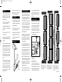
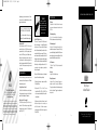
DS00348ACN/IRB1
11/26/03
12:05 PM
Page 2
INSTALLATION & OPERATION GUIDE
eighteen gauge two-conductor wire. For distances of up to two hundred feet use a sixteen
gauge two-conductor wire.
BE SURE TO OBSERVE PROPER POLARITY
WHEN EXTENDING THE FLASHER WIRE.
The wire lead marked with a gray stripe
is positive (+); the unmarked lead is negative (-).
Mounting the IRB1
Test the operation of the IRB1 in the planned
mounting location. If all of the components
operate correctly via the IR repeater system,
mount the IRB1 using it’s self-adhesive strip.
Make sure the mounting surface is clean and
dry. Remove the protective coating from the
back of the strip attached to the IRB1 and stick it
in place. Coil any excess connecting wire and
tie it in place.
TROUBLESHOOTING
This troubleshooting guide discusses the most
common problems that prevent an IR flasher
from operating correctly.
Niles Audio Corporation
12331 S.W. 130 Street Miami, Florida 33186
Tel: (305) 238-4373 Fax: (305) 238-0185
www.nilesaudio.com
©2004 Niles Audio Corporation. All rights reserved. Niles, the Niles logo
and Blending High Fidelity and Architecture are registered trademarks of
Niles Audio Corporation. Because we strive to improve our products,
Niles reserves the right to change product specifications without notice.
The technical and other information contained herein is not intended to
set forth all technical and other specifications of Niles products. Additional
information can be obtained on-line at www.nilesaudio.com or by calling
Niles at 1-800-289-4434. 01/04 Printed in China DS00348ACN
“TECH TIP”
Wire size is expressed by its
AWG (American Wire Gauge)
number. The lower the number,
the larger the wire, i.e. twelve
AWG is physically larger
than fourteen AWG.
Optical IR Feedback Loop
If there is an IR sensor and an IR flasher located
within the same room—an “optical IR feedback
loop” can occur. This occurs when the IR output
from a flasher unintentionally reaches an IR sensor located within the same room. The IR commands are eventually forwarded back to the IR
flasher and the whole process endlessly repeats
itself. This effect is similar to acoustical feedback
(the howling or whistling sound heard in a P.A.
system when the microphone is placed too
close to the speaker).
The optical IR feedback loop can be eliminated
by one of the two following methods.
1. Relocating the sensor in order to break the
IR feedback loop.
Testing the Remote Control
Test that the hand-held remote control operates
the component when you point it at the front
panel (check the batteries if it does not).
2. Replace the IRB1 with a MF Series
MicroFlasher (MF1, MF1VF, MF2, MF2VF) for
each component controlled by the problemcausing flasher.
Main System Unit Power Supply
Check that the red power light on the main system unit is lit (the in-line power supply should
be plugged into an active AC wall outlet and
supplying 12V DC).
If problems persist, refer to the user’s manual
for the main system unit or contact your
local Niles dealer. If further assistance
is required contact Niles Technical Support at
1-800-289-4434.
7
8
SPECIFICATIONS
IR System
Compatible with virtually all brands of remotes
using carrier frequencies between 20 and
455 kHz.
IR Transmitting Range
18' to 30' if mounted so that the transmitting
LEDs face the sensors in a direct line of sight.
IR Transmitting Angle
Variable with the brand and/or model of the
audio/video component. Because of the high
power and “flooding” pattern of the IRB1, extreme
transmitting angles can be successfully used if the
sensor window of the component is close.
Unit Dimensions
1" Wide x 2" High x 3/4" Deep (Includes double
sided tape).
Mounting
Supplied with self-adhesive tape.
IRB1
Wiring Requirements
Supplied with 10' of 2-conductor 22 gauge connecting wire and 3.5mm plug. Substitute an
18 gauge 2-conductor wire for distances ranging
from 10 to 20' and a 16 gauge 2-conductor wire
for up to 200'.
9
High Ouput
Infrared Flasher
10
B
L E N D I N G
A N D
A
H
I G H
F
I D E L I T Y
R C H I T E C T U R E
®
DS00348ACN/IRB1
11/26/03
12:05 PM
INTRODUCTION
The IRB1 is a small, cabinet-mount high output
infrared flasher. The IRB1 is just one part of the
three building blocks necessary to complete a
Niles IR extender system:
• IR Main System Unit—Models MSU140,
MSU250, MSU480 and MSU440Z.
• IR Sensors/Keypads—Models WS100, TS100,
MS100, MS200, CS100, MVC100IR and the
IntelliPad®.
Page 1
The IRB1 is compatible with all Niles infrared
extenders systems, IntelliControl ® and
MultiZone recivers and preamplifiers.
FEATURES & BENEFITS
• Two infrared LEDs give the IRB1 exceptional
range and power. With proper placement, a
single IRB1 flasher can control an entire stack
of audio/video components.
• The IRB1 is equipped with a 3.5mm plug.
This provides you with easy hookup.
• IR Flashers—Models MF1, MF1VF, MF2,
MF2VF and the IRB1.
• An adhesive-backed strip is included with the
IRB1, providing quick, secure, mounting.
An IR sensor expansion hub, Model IRH610,
is available to provide additional sensor inputs
to your system.
• The IRB1 is supplied with an ample 10' of
connecting wire.
When an IR remote sensor receives a command
from a hand-held remote control, it sends a corresponding electronic signal through a wire to
the main system unit. Here, the main system
unit cleans and amplifies the electronic signal.
Finally, the main system unit outputs the signal
to the IR flasher which relays the infrared command to the audio/video component you wish
to control.
IRB1 PARTS GUIDE
Double
sided tape
10 feet of
2-conductor
22 gauge
connecting
wire
The IRB1 relays the infrared command using
“flashes” of infrared light in a powerful flooding pattern from its two infrared LEDs. The output is extraordinarily accurate over a wide
bandwidth. This allows the IRB1 to control
most makes and models of IR controlled
audio/video components.
1
3.5mm Plug
2
INSTALLATION CONSIDERATIONS
The IRB1 is typically used as a “flooding” flasher
to control a stack of audio/video components.
For this type of application, place the IRB1 with
its LEDs pointed straight up and at least an inch
in front of the equipment you wish to control
(See Figure 2). The effective range varies
between 8' to 30' depending on the brand
and/or the model of the audio/video component. Note: If cabinet dimensions permit, experimenting with the placement of the IRB1 may
yield better operating results.
For tall stacks of components use multiple IRB1
flashers. For example, place one IRB1 at the top
of a stack with the LEDs pointing down and one
IRB1 at the base of the stack with the LEDs
pointing up (See Figure 3).
In some installations there are shelves blocking
a direct path between the IRB1 and the components’ IR sensor window. It is possible to
bounce infrared light off of smooth reflective
surfaces (particularly white surfaces). If a suitable surface exists (like the back of a cabinet
door, or a white wall within a few feet) try to
place the IRB1 so that its reflected output reaches the sensor windows of the components (See
Figure 4). If some of the components are still not
getting adequate signal, mount a Niles MF series
MicroFlasher® on the sensor window of each of
the problematic components.
a room. In this type of situation the IRB1 has an
effective operational range of 18' to 30'
(depending on brand and model of audio/video
equipment).
INSTALLATION & OPERATION
Route the connecting wire to the main system
unit. Most Niles IR main system units feature
specific flasher outputs that are selectable
between low and high output. Insert the 3.5mm
plug of the IRB1into one of these selectable
“FLASHER OUTPUTS” jacks on the MSU. Slide
the corresponding switch on the MSU to the
”high” position (See Figure 1).
FIGURE 1 Connecting the IRB1 to the main system
unit’s flasher outputs.
Sometimes, it is desirable to mount the IRB1 so
that it directly faces the equipment from across
Increasing the Wire Length
If the connecting wire is too short to reach the
main system unit, a new length of heavier gauge
wire should be spliced onto a six inch length of
the original wire. For distances between ten and
twenty feet upgrade the original wire to an
3
4
FIGURE 2 IRB1 placed at the bottom of the cabinet controlling a
stack of components .
5
FIGURE 3 IRB1 placed at the bottom and the top of the cabinet controlling a tall stack of components.
FIGURE 4 IRB1 placed facing the
cabinet door controlling a stack of
components by reflecting infrared
commands.
6
Over Please
DS00348ACN/IRB1
11/26/03
12:05 PM
Page 2
INSTALLATION & OPERATION GUIDE
eighteen gauge two-conductor wire. For distances of up to two hundred feet use a sixteen
gauge two-conductor wire.
BE SURE TO OBSERVE PROPER POLARITY
WHEN EXTENDING THE FLASHER WIRE.
The wire lead marked with a gray stripe
is positive (+); the unmarked lead is negative (-).
Mounting the IRB1
Test the operation of the IRB1 in the planned
mounting location. If all of the components
operate correctly via the IR repeater system,
mount the IRB1 using it’s self-adhesive strip.
Make sure the mounting surface is clean and
dry. Remove the protective coating from the
back of the strip attached to the IRB1 and stick it
in place. Coil any excess connecting wire and
tie it in place.
TROUBLESHOOTING
This troubleshooting guide discusses the most
common problems that prevent an IR flasher
from operating correctly.
Niles Audio Corporation
12331 S.W. 130 Street Miami, Florida 33186
Tel: (305) 238-4373 Fax: (305) 238-0185
www.nilesaudio.com
©2004 Niles Audio Corporation. All rights reserved. Niles, the Niles logo
and Blending High Fidelity and Architecture are registered trademarks of
Niles Audio Corporation. Because we strive to improve our products,
Niles reserves the right to change product specifications without notice.
The technical and other information contained herein is not intended to
set forth all technical and other specifications of Niles products. Additional
information can be obtained on-line at www.nilesaudio.com or by calling
Niles at 1-800-289-4434. 01/04 Printed in China DS00348ACN
“TECH TIP”
Wire size is expressed by its
AWG (American Wire Gauge)
number. The lower the number,
the larger the wire, i.e. twelve
AWG is physically larger
than fourteen AWG.
Optical IR Feedback Loop
If there is an IR sensor and an IR flasher located
within the same room—an “optical IR feedback
loop” can occur. This occurs when the IR output
from a flasher unintentionally reaches an IR sensor located within the same room. The IR commands are eventually forwarded back to the IR
flasher and the whole process endlessly repeats
itself. This effect is similar to acoustical feedback
(the howling or whistling sound heard in a P.A.
system when the microphone is placed too
close to the speaker).
The optical IR feedback loop can be eliminated
by one of the two following methods.
1. Relocating the sensor in order to break the
IR feedback loop.
Testing the Remote Control
Test that the hand-held remote control operates
the component when you point it at the front
panel (check the batteries if it does not).
2. Replace the IRB1 with a MF Series
MicroFlasher (MF1, MF1VF, MF2, MF2VF) for
each component controlled by the problemcausing flasher.
Main System Unit Power Supply
Check that the red power light on the main system unit is lit (the in-line power supply should
be plugged into an active AC wall outlet and
supplying 12V DC).
If problems persist, refer to the user’s manual
for the main system unit or contact your
local Niles dealer. If further assistance
is required contact Niles Technical Support at
1-800-289-4434.
7
8
SPECIFICATIONS
IR System
Compatible with virtually all brands of remotes
using carrier frequencies between 20 and
455 kHz.
IR Transmitting Range
18' to 30' if mounted so that the transmitting
LEDs face the sensors in a direct line of sight.
IR Transmitting Angle
Variable with the brand and/or model of the
audio/video component. Because of the high
power and “flooding” pattern of the IRB1, extreme
transmitting angles can be successfully used if the
sensor window of the component is close.
Unit Dimensions
1" Wide x 2" High x 3/4" Deep (Includes double
sided tape).
Mounting
Supplied with self-adhesive tape.
IRB1
Wiring Requirements
Supplied with 10' of 2-conductor 22 gauge connecting wire and 3.5mm plug. Substitute an
18 gauge 2-conductor wire for distances ranging
from 10 to 20' and a 16 gauge 2-conductor wire
for up to 200'.
9
High Ouput
Infrared Flasher
10
B
L E N D I N G
A N D
A
H
I G H
F
I D E L I T Y
R C H I T E C T U R E
®
DS00348ACN/IRB1
11/26/03
12:05 PM
Page 2
INSTALLATION & OPERATION GUIDE
eighteen gauge two-conductor wire. For distances of up to two hundred feet use a sixteen
gauge two-conductor wire.
BE SURE TO OBSERVE PROPER POLARITY
WHEN EXTENDING THE FLASHER WIRE.
The wire lead marked with a gray stripe
is positive (+); the unmarked lead is negative (-).
Mounting the IRB1
Test the operation of the IRB1 in the planned
mounting location. If all of the components
operate correctly via the IR repeater system,
mount the IRB1 using it’s self-adhesive strip.
Make sure the mounting surface is clean and
dry. Remove the protective coating from the
back of the strip attached to the IRB1 and stick it
in place. Coil any excess connecting wire and
tie it in place.
TROUBLESHOOTING
This troubleshooting guide discusses the most
common problems that prevent an IR flasher
from operating correctly.
Niles Audio Corporation
12331 S.W. 130 Street Miami, Florida 33186
Tel: (305) 238-4373 Fax: (305) 238-0185
www.nilesaudio.com
©2004 Niles Audio Corporation. All rights reserved. Niles, the Niles logo
and Blending High Fidelity and Architecture are registered trademarks of
Niles Audio Corporation. Because we strive to improve our products,
Niles reserves the right to change product specifications without notice.
The technical and other information contained herein is not intended to
set forth all technical and other specifications of Niles products. Additional
information can be obtained on-line at www.nilesaudio.com or by calling
Niles at 1-800-289-4434. 01/04 Printed in China DS00348ACN
“TECH TIP”
Wire size is expressed by its
AWG (American Wire Gauge)
number. The lower the number,
the larger the wire, i.e. twelve
AWG is physically larger
than fourteen AWG.
Optical IR Feedback Loop
If there is an IR sensor and an IR flasher located
within the same room—an “optical IR feedback
loop” can occur. This occurs when the IR output
from a flasher unintentionally reaches an IR sensor located within the same room. The IR commands are eventually forwarded back to the IR
flasher and the whole process endlessly repeats
itself. This effect is similar to acoustical feedback
(the howling or whistling sound heard in a P.A.
system when the microphone is placed too
close to the speaker).
The optical IR feedback loop can be eliminated
by one of the two following methods.
1. Relocating the sensor in order to break the
IR feedback loop.
Testing the Remote Control
Test that the hand-held remote control operates
the component when you point it at the front
panel (check the batteries if it does not).
2. Replace the IRB1 with a MF Series
MicroFlasher (MF1, MF1VF, MF2, MF2VF) for
each component controlled by the problemcausing flasher.
Main System Unit Power Supply
Check that the red power light on the main system unit is lit (the in-line power supply should
be plugged into an active AC wall outlet and
supplying 12V DC).
If problems persist, refer to the user’s manual
for the main system unit or contact your
local Niles dealer. If further assistance
is required contact Niles Technical Support at
1-800-289-4434.
7
8
SPECIFICATIONS
IR System
Compatible with virtually all brands of remotes
using carrier frequencies between 20 and
455 kHz.
IR Transmitting Range
18' to 30' if mounted so that the transmitting
LEDs face the sensors in a direct line of sight.
IR Transmitting Angle
Variable with the brand and/or model of the
audio/video component. Because of the high
power and “flooding” pattern of the IRB1, extreme
transmitting angles can be successfully used if the
sensor window of the component is close.
Unit Dimensions
1" Wide x 2" High x 3/4" Deep (Includes double
sided tape).
Mounting
Supplied with self-adhesive tape.
IRB1
Wiring Requirements
Supplied with 10' of 2-conductor 22 gauge connecting wire and 3.5mm plug. Substitute an
18 gauge 2-conductor wire for distances ranging
from 10 to 20' and a 16 gauge 2-conductor wire
for up to 200'.
9
High Ouput
Infrared Flasher
10
B
L E N D I N G
A N D
A
H
I G H
F
I D E L I T Y
R C H I T E C T U R E
®