1
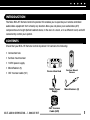
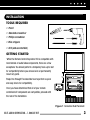
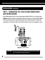
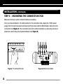
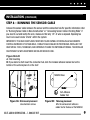
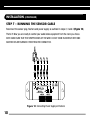
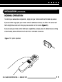
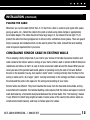
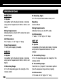
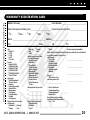
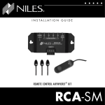
I N S TA L L AT I O N G U I D E
®
REMOTE CONTROL ANYWHERE! KIT
RCA-HT
CONGRATULATIONS!
Thank you for choosing the RCA-HT Remote Control Anywhere! Kit from Niles. With proper
installation and operation, you should enjoy years of trouble-free use.
Niles manufactures the industry’s most complete line of custom installation components and
accessories for audio/video systems. To see the complete Niles product assortment, visit us on the
internet at: www.nilesaudio.com.
TABLE OF CONTENTS
II
Introduction
1
Contents
1
Installation Considerations
2
Installation
3
Specifications
18
Limited Warranty
20
INTRODUCTION
The Niles RCA-HT Remote Control Anywhere! Kit enables you to operate your remote controlled
audio/video equipment from virtually any location. Now you can place your audio/video (A/V)
components out of sight (behind cabinet doors, in the rear of a room, or in a different room) and still
conveniently control your system.
CONTENTS
Check that your RCA-HT Remote Control Anywhere! Kit contains the following:
• Connection hub
• Surface mount sensor
• 12VDC power supply
• MicroFlashers (5)
• CAT 5 sensor cable (50’)
Connection Hub
12VDC Power
Supply
NILES AUDIO CORPORATION – 1-800-BUY-HIFI
CAT 5 sensor
Cable (50ft)
Surface Mount
Sensor
MicroFlashers (3)
1
INSTALLATION CONSIDERATIONS
WARNING – TO PREVENT POSSIBLE INJURY, THE FOLLOWING BASIC SAFETY PRECAUTIONS SHOULD BE
OBSERVED IN THE INSTALLATION AND USE OF YOUR REMOTE CONTROL ANYWHERE KIT.
1. Read through the entire manual – Before attempting any installation, read this manual
thoroughly and keep it for future reference.
2. Avoid contact with all high voltage electrical wiring and equipment!
3. Keep away from water and moisture – Never use or install electronic products near water,
ie., near a bathtub, sink, washing machine, in a wet basement, near a swimming pool, or
anywhere else the product may be exposed to water or moisture.
4. Power supply cord protection – Do not run the power cord where it may be subject to wear or
abuse. Do not allow anything to rest on or roll over the power cord which may damage it.
6. Lightning – It is suggested that you remove the power supply from the wall if your system will
not be used for long periods of time. Power surges due to lightning strikes may damage your
equipment.
7. Check your local building and electrical codes – There may be specific requirements regarding running low voltage in your area.
2
INSTALLATION
TOOLS REQUIRED
• Pencil
• Standard screwdriver
• Phillips screwdriver
• Wire strippers
• Drill (and assorted bits)
GETTING STARTED
While the Remote Control Anywhere! Kit is compatible with
most brands of audio/video components, there are a few
exceptions. You should perform a temporary hook-up to test
for compatibility before you conceal wire or permanently
mount any parts.
Steps One through Five describe how to perform a quick
and easy check for compatibility.
Once you have determined that all of your remote
controlled A/V components are compatible, proceed with
the rest of the installation.
Figure 1 Connection Hub Placement
NILES AUDIO CORPORATION – 1-800-BUY-HIFI
3
INSTALLATION
STEP 1 – PLACING THE CONNECTION HUB
Place the Connection Hub so that the MicroFlasher wires will reach the components.
Never place the connection hub closer than 1’ away from a television set (Figure 1).
To Niles IR Flasher
To unswitched
AC Outlet
To 12VDC Power Supply
Plugged into a switched
AC Outlet. Typically
found in back
of a receiver.
MSU250
MS210 Sensor
MSU250 Sensor
Connection
Figure 2: MSU250 Installation
4
INSTALLATION
(CONTINUED)
STEP 2 – CONNECTING THE SENSOR CABLE TO
THE CONNECTION HUB
For your convenience, the sensor cable ends have been stripped.
Insert each wire into the appropriate hole on the removable connector plug (Figure 2), and snap the
locking tab down. To help you, the connector plug is keyed. Insert the smooth side of the connector
plug into the smooth side of the socket. Don’t force the scalloped side of the connector plug into
the smooth side of the socket. Make sure that the orientation of the connector matches the sensor
(Figure 3 & 4).
Figure 3: Removable Connector Plug
Figure 4: Wiring Legend
TECH TIP: Wire size is expressed by it’s AWG (American Wire Gauge) number. The lower
the AWG number, the larger the wire, i.e., 20 AWG wire is physically larger than 22 AWG.
NILES AUDIO CORPORATION – 1-800-BUY-HIFI
5
INSTALLATION
(CONTINUED)
STEP 3 – CONNECTING THE 12VDC IN-LINE POWER SUPPLY
AND MICROFLASHERS
Plug the MicroFlashers into any of the sockets labeled FLASHER OUTPUTS on the connection hub
(Figure 5). Plug the connector on the supplied 12VDC power supply into the socket labeled POWER
on the connection hub and then plug the wall adapter into a live electrical outlet. The power LED
should light. If the LED does not light, confirm that the outlet you used is live by plugging in a lamp.
Figure 5: Connection Ports
TECH TIP: Make all final connections to the MSU before connecting the power supply.
This will avoid potential damage to components.
6
INSTALLATION
(CONTINUED)
STEP 4 – MOUNTING A MICROFLASHER TO A/V COMPONENTS
Make sure all of your remote controls have batteries and that they are able to operate the A/V components. Locate a place for the remote control that is within arm’s length of the A/V components,
yet cannot directly control them. Place the table-top sensor no closer than two feet in front of the
remote control (Figure 6).
Hold the MicroFlasher four inches in front of the remote sensor window on the A/V component’s
front panel. Press buttons on the remote control while watching the front panel of the A/V component. When the component responds repeatedly to the commands, peel off the protective backing
on the MicroFlasher and place the MicroFlasher in that location.
If the A/V component’s remote sensor is not clearly
marked, slowly move the MicroFlasher over the window of the A/V component while pushing buttons on
the remote control until you get a response (Figure 7).
Repeat this procedure for each A/V component you
wish to control.
When the A/V component responds repeatedly, peel off
the protective backing on the MicroFlasher and place
the MicroFlasher in that location.
NILES AUDIO CORPORATION – 1-800-BUY-HIFI
7
INSTALLATION
(CONTINUED)
STEP 5 – MOUNTING THE CONNECTION HUB
Make sure that your system tested OK before proceeding
Once you have decided on the ideal location for the connection hub, unplug the 12VDC power
supply from the electrical outlet and disconnect the sensor and the MicroFlasher cables from the
connection hub (Figure 8). The connection hub can be either mounted on a wall using screws or
placed on a shelf using the included adhesive feet (Figure 9).
Figure 7: Locating IR Sensor
8
Figure 8: Removing Cables
INSTALLATION
(CONTINUED)
STEP 6 – RUNNING THE SENSOR CABLE
Conceal the sensor cable between the sensor and the connection hub.For specific information refer
to “Running Sensor Cable in New Construction” or “Concealing Sensor Cable in Existing Walls”.If
you need to cut and restrip the wire, make sure that only 1/4” of wire is exposed. Exposing too
much wire could create “shorts” within the system.
IMPORTANT: IF YOU HAVE DOUBTS ABOUT WHETHER YOU ARE CAPABLE OF INSTALLING A NILES REMOTE
CONTROL ANYWHERE! KIT IN YOUR WALLS, CONSULT A NILES DEALER OR PROFESSIONAL INSTALLER. THEY
HAVE SPECIAL TOOLS, TECHNIQUES, AND EXPERIENCE TO MAKE THE IMPOSSIBLE POSSIBLE. THE INSTALLER
CAN PROVIDE YOU WITH AN ESTIMATE BEFORE ANY WORK IS DONE.
Figure 9A & B
A: Wall mounting
B: If you desire to shelf mount the connection hub, stick the included adhesive backed feet on the
bottom of the unit and place it on the shelf
MSU250 Base
Self-Adhesive
Rubber Feet
Figure 9A: Wall-mount placement
Use sheetrock screws
NILES AUDIO CORPORATION – 1-800-BUY-HIFI
Figure 9B: Table-top placement
Affix the enclosed self-adhesive
rubber feet to the base of the MSU250
9
INSTALLATION
(CONTINUED)
STEP 7 – RUNNING THE SENSOR CABLE
Reconnect the sensor plug, flashers and power supply as outlined in steps 2, 3 and 4 (Figure 10).
That’s it! Now you are ready to control your audio/video equipment from the room you chose.
NOTE: MAKE SURE THAT THE STRIPPED ENDS OF THE WIRE DO NOT COME IN CONTACT WITH ONE
ANOTHER OR ANY SURFACE OTHER THAN THE CONNECTOR.
Figure 10: Connecting Power Supply an Flashers
10
INSTALLATION
(CONTINUED)
NORMAL OPERATION
To control your audio/video components, simply aim your remote control at the table-top sensor.
If you are within range (and your remote control’s batteries are fresh), the LED on the sensor will
flash a bright blue color each time you press a button on the remote (Figure 11).
If you are using a remote control with macro capabilities (a single press of a button issues a string
of commands), allow sufficient time for all of the commands to execute.
Figure 11: System Operation
NILES AUDIO CORPORATION – 1-800-BUY-HIFI
11
INSTALLATION
(CONTINUED)
OPTIONAL ACCESSORIES
STATUS FEEDBACK WALL ADAPTER
The sensor features a status feedback LED that glows green whenever your system is on. This is
a very useful feature when operating your equipment from a remote location. For this feature to
work, your system receiver (or preamp) must have a switched AC outlet and you must purchase
the optional Status Feedback 12VDC Wall Adapter (FG01035). The Status Feedback wall adapter
is plugged into the switched AC outlet of your receiver. The 12VDC output plug is inserted into the
connection hub’s Status Input (Figure 12).
Figure 12: Connecting the Status Adaptor
REMOTE CONTROL ANYWHERE! KIT
CONNECTION HUB
12
INSTALLATION
(CONTINUED)
ADDITIONAL SENSORS
The Remote Control Anywhere! Kit includes one surface mount sensor. The included MSU250 main
system unit will accommodate a second IR sensor. Niles makes a variety of sensors for virtually any
application. See your Niles dealer for more information.
RUNNING SENSOR CABLE IN NEW CONSTRUCTION
SCHEDULING AND PREPARATION
Plan to schedule the sensor wiring after the electrical wiring is finished. That way you can avoid
cable routes which could potentially induce interference over the sensor cable. The basic rules are:
Never run the sensor cable through the same hole as an electrical cable.
Never run the sensor cable into the same J-box as electrical cable.
Avoid running the sensor cable beside the electrical cable. Keep it at least 3 or 4 feet distant
from any electrical power cable.
As side-by-side wiring is unavoidable in particular spots in every house, just move the sensor cable
route away as soon as possible. If construction forces a side by side run for more than ten feet,
install metal conduit or shielded sensor cable. Low-voltage cables such as doorbells, intercoms,
telephone, speaker, security, or television cannot cause interference on your sensor cables, so you
can safely run all of them at the same time, through the same holes, side-by-side.
NILES AUDIO CORPORATION – 1-800-BUY-HIFI
13
INSTALLATION
(CONTINUED)
SAFETY FIRST!
Wear gloves, safety goggles and head protection when drilling. Avoid nails, they ruin bits and they
can cause injury. Pay particular attention when using “hole-hogs” and other powerful electric drills;
the torque of the drill when suddenly stopped by a nail can break a strong person’s wrist.
DRILLING
Use a bit that is large enough for the cables you plan to run. An auger bit is the preferred bit for
rough-in wiring. It will actually pull itself through the wood, so that the drill motor, not you, does
most of the work.
Always drill the holes in the center of the stud. If you have to notch the stud or drill the hole closer
than one inch from the edge of the stud, protect the cable with a nail plate.
When drilling holes in ceiling joists, drill in the center of the joists and try to locate the hole near
the end of the joist. DO NOT drill through a “gluelam” or any load bearing beam without the
direction of your contractor.
Try to line the holes up perfectly, because it makes pulling the cable much easier. A good technique
is to snap a chalk line across the face of the studs or against the bottom of the ceiling joists. Then
work backward so that you can always see the holes you have already drilled. Paying careful
attention to this will save you a lot of time later!
14
INSTALLATION
(CONTINUED)
PULLING THE CABLE
Whenever you run the cable farther than 4-1/2 feet from a hole in a stud or joist (open attic space,
going up walls, etc.), fasten the cable to the joists or studs using cable clamps or appropriately
sized cable staples. The cable should not have large sags in it, nor should it be too tight. Try to
protect the cable from being stepped on in attics or other unfinished crawl spaces. There are guard
strips, raceways and conduits which can be used to protect the cable. Consult the local building
code for special requirements in your area.
CONCEALING SENSOR CABLE IN EXISTING WALLS
This is actually a fairly simple task if you restrict your choice of the table-top sensor location and
cable routes to the interior walls or ceilings of your home. Interior walls in almost all North American
residences are hollow, so that it is easy to route new sensor cable around the house. What you see
when you look at the painted wall board, plaster, or paneling is only the skin of the wall. Behind
the skin is the skeleton; two-by-four wood or metal “studs” running vertically from the floor to the
ceiling in walls and 2 x 6 or larger “joists” running horizontally in the ceilings and floors. In between
the studs and the joists is the space for the wiring and plumbing of your home.
Exterior walls are different. They must insulate the house from the heat and cold outside, so they
are stuffed with insulation. The national building code requires that the hollow wall space in exterior
walls be broken by a horizontal stud placed between the vertical studs. This “fire blocking” makes
it very difficult to retrofit long lengths of cable. In some areas of the country the exterior walls are
constructed of solid masonry, and have no hollow space for cables.
NILES AUDIO CORPORATION – 1-800-BUY-HIFI
15
INSTALLATION
(CONTINUED)
Start by examining all the possible routes you might take to run the sensor cable from the sensor
location to the A/V components to be controlled. Use a stud sensor or other device to locate the
internal structure of the wall. You want to avoid all studs or joists. A typical route would be from the
sensor location up the inside of the wall to a new hole drilled into the top “plate” (horizontal 2 x 4
at the top of the inside of the wall), into the attic crawl space, then down another plate to the wall
behind the stereo system itself. The other very common route is through the bottom plate of the wall
into an unfinished basement or crawl space.
Identify where all of your electrical, phone, and TV wiring is likely to be and plan to route around
it all. You can accidentally induce interference on your sensor cable right beside electrical cable
for more than a few feet. Try to keep sensor cable running parallel to power cables at least 3 feet
away. To find exactly where an electrical cable is routed, try inspecting the inside of the wall by
turning off the breaker for a particular power outlet or switch, removing the cover plate and switch
or receptacle, and shining a penlight into the wall. If you have access to an attic or basement space,
you can see which part of the wall space is free of obstructions (Figure 13).
When you don’t have access above or below the wall, try to estimate the existing cable and pipe
locations from the positions of electrical outlets and plumbing fixtures on both sides of the wall.
Also, take a look at the outside of your house, sometimes a conduit, vent or drain pipe will be visible
and will offer useful information. Choose the route with the fewest potential obstacles. If your house
is built on a slab or you are wiring between two finished floors, look for baseboards which could
be removed and replaced with the cable behind them. Doorjambs can be removed and often have
enough space for sensor cable all the way around the door (Figure 14).
16
INSTALLATION
(CONTINUED)
Sometimes, an under-the-carpet run is possible. As a last resort, heating and air conditioning vents
can be used as cable raceways for plenum rated cable (check your local building codes, some
municipalities require a conduit).
When you are dealing with the unknown because of the structure of your home, or with difficult
materials to patch the wall, such as plaster, lath and plaster, faux finishes, wallpaper etc., be
patient. A careful study of the potential problems before you start the job will pay off later.
Figure 13: Unobstructed space
for sensor cable
NILES AUDIO CORPORATION – 1-800-BUY-HIFI
Figure 14: Routing Wire
Around a Door
17
SPECIFICATIONS
MSU250
IR System
Compatible with virtually all brands of remotes
using carrier frequencies of 38kHz, 40kHz, and
56kHz
Wiring Requirements
Individual home-runs of CAT 5 cable from each
sensor/keypad
Unit Dimensions
5-5/8” wide x 1-1/4” high x 2” deep
Power Requirements
12 vDC power supply (included)
MS210
IR System
Compatible with virtually all brands of remotes
using carrier frequencies of 38kHz, 40kHz, and
56kHz
IR Receiving Range
20’ to 35’ depending upon the strength of the
remote control
18
IR Receiving Angle
60° off-axis (horizontal and vertical) at 20’
Mounting
Surface Mount
Wiring Requirements
Individual home-runs of CAT 5 cable
Unit Dimensions
2” wide x 11/16” high x 1/2” deep
MF1VF
IR System
Compatible with virtually all brands of remotes
using carrier frequencies between 20 and
455kHz
IR Transmitting Range
20’ to 35’ depending upon the strength of the
remote control
IR Transmitting Angle
Transmits in a “pinpoint” transmission pattern
(the off-axis power drops off very rapidly)
Unit Dimensions
5/16” wide x 3/16” high x 1/2” long
NOTES
NILES AUDIO CORPORATION – 1-800-BUY-HIFI
19
LIMITED WARRANTY
Niles Audio Corporation (“NILES”) warrants its active products (those requiring AC or battery power) to the original purchaser to be free
of manufacturing defects in material and workmanship for a period of two years from date of purchase.
This Warranty is subject to the following additional conditions and limitations. The Warranty is void and inapplicable if NILES deems
that the product has been used or handled other than in accordance with the instructions provided by the manufacturer, including
but not limited to damage caused by accident, mishandling, improper installation, abuse, negligence, or normal wear and tear, or
any defect caused by repair to the product by anyone other than NILES or an authorized NILES dealer.
To obtain warranty service, take the unit to the nearest authorized NILES dealer, who will test the product and if necessary, forward
it to NILES for service. If there are no authorized NILES dealers in your area, you must write to NILES and include your name,
model and serial number of your unit, along with a brief description of the problem. A factory Return Authorization Number will
be sent to you. DO NOT RETURN ANY UNIT WITHOUT FIRST RECEIVING WRITTEN AUTHORIZATION AND SHIPPING INSTRUCTIONS
FROM NILES.
If the above conditions are met, the purchaser’s sole remedy shall be to return the product to NILES, in which case NILES will repair
or replace, at its sole option, the defective product without charge for parts or labor. NILES will return a unit repaired or replaced
under warranty by shipping same by its usual shipping method from the factory (only) at its expense within the United States of
America. THERE ARE NO OTHER WARRANTIES, INCLUDING WITHOUT LIMITATION, EITHER EXPRESS OR IMPLIED WARRANTIES OF
MERCHANTABILITY OR FITNESS FOR A PARTICULAR PURPOSE, WITH RESPECT TO THE PRODUCT.
REPAIR OR REPLACEMENT AS PROVIDED UNDER THIS WARRANTY IS THE EXCLUSIVE REMEDY OF THE CONSUMER/PURCHASER.
NILES SHALL NOT BE RESPONSIBLE FOR ANY INCIDENTAL OR CONSEQUENTIAL DAMAGES EXCEPT TO THE EXTENT PROVIDED (OR
PROHIBITED) BY APPLICABLE LAW.
Some states do not allow the exclusion or limitation of incidental or consequential damages, so the above limitation may not apply to you.
This warranty gives you specific legal rights, and you may also have other rights which vary from state to state.
For the name of your nearest authorized NILES dealer, contact:
NILES AUDIO CORPORATION, P.O. BOX 160818, Miami, Florida 33116.
Please fill in your product information and retain for your records.
Model ____________________________ Serial No. _________________________ Purchase Date ____________
20
Detach here and return to: Niles Audio Corporation Warranty Registration Dept. P.O. Box 160818 Miami, Florida 33116-0818
WARRANTY REGISTRATION CARD
Model Purchased __________________________________ Serial Number __________________________
Date Purchased (month/day/year) ______________________ Dealer Name and Location _________________
❍ Dr.
❍ Miss
❍ Mr.
❍ Mrs.
❍ Ms.
Name ____________________________________ Address _____________________________________
City _______________________________State __________Zip ___________ Tel (
Age:
❍ Under 25
❍ 25-34
❍ 35-44
❍ 45-54
❍ 55 & over
Income:
❍ Under $24,999
❍ $25,000-$44,999
❍ $45,000-$74,999
❍ $75,000-$99,999
❍ $100,000-$129,999
❍ Over $130,000
Occupation:
❍ Arts/Entertainment
❍ Business Owner
❍ Engineer
❍ Finance/Accounting
❍ General Office
❍ Management
❍ Professional
❍ Sales/Marketing
❍ Student
❍ Tradesperson
Musical tastes: (Please check
all that apply)
❍ Alternative ❍ Classical
❍ Country
❍ Jazz
❍ New Age ❍ Popular
❍ R&B
❍ Rock
❍ Other ________________
How did you hear about Niles?
❍ Architect/Developer
❍ Custom Installer
❍ Direct Mail
❍ Friend/Family
❍ In-Store Display
❍ Interior Designer
❍ Magazine Ad
❍ Mail-Order Catalog
❍ Newspaper Ad
❍ Product Brochure
❍ Product Review
❍ Retail Salesperson
❍ E-Tailer
What magazines do you read?
1. _____________________
2. _____________________
3. _____________________
Who will install the product?
❍ Custom Installer
❍ Electrician
❍ Friend
NILES AUDIO CORPORATION – 1-800-BUY-HIFI
❍ Myself
) ____________
Are there products/capabilities
Which factor(s) influenced the purchase that you would like to see introduced?
of your Niles product? (Please check
all that apply)
❍ Ease of Use
________________________
❍ Price/Value
❍ Product Features
❍ Quality/Durability
________________________
❍ Reputation
❍ Style/Appearance
❍ Warranty
________________________
Do you . . . ?
❍ Own a House. If yes,
how many square feet?
________________________
______________________
❍ Own a Town House/
Condominium/Co-op
❍ Rent an Apartment
❍ Rent a House
Are you interested in receiving
literature on other Niles products?
❍ Yes ❍ No
21
BLENDING HIGH FIDELITY AND ARCHITECTURE®
Niles Audio Corporation
1 2 3 3 1 S . W. 1 3 0 S t r e e t M i a m i , F l o r i d a 3 3 1 8 6
1 - 8 0 0 - B U Y- H I F I – w w w. n i l e s a u d i o . c o m
©2007 Ni les A ud i o C o r po r ati o n . A l l r i g h ts r es er ve d . Ni l e s, the Ni l e s lo go s an d
Blen di n g Hig h Fideli ty a nd A r c h i te c tur e a r e r e g i ste r e d tr ad e mar k s o f Ni l es Au dio C or pora t io n.
All oth er tradem ar k s a r e the p r o pe r ty o f the i r r es pe c ti ve o wn e r s. 0 4 / 0 7 D S 0 0 5 6 6 A