1
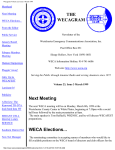
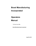
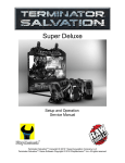
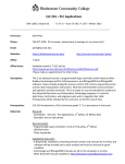
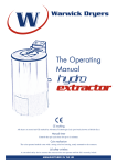
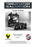
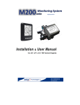
PROTOTYPE TRAILER-LOADING ROBOT
John J. Ottersbach
Robert L. Williams II
Ohio University
Athens, OH 45701
Final Finished Manuscript Version
Industrial Robot: An International Journal
December, 1999
Keywords:
Pallet-loading robot, trailer-loading robot, autonomous pallet loading, semi-trailer loading
dock automation
Contact author information:
Robert L. Williams II, Ph.D.
Assistant Professor
Department of Mechanical Engineering
257 Stocker Center
Ohio University
Athens, OH 45701-2979
phone: (740) 593 - 1096
fax:
(740) 593 - 0476
email: [email protected]
URL: http://www.ent.ohiou.edu/~bobw
PROTOTYPE TRAILER-LOADING ROBOT
John J. Ottersbach and Robert L. Williams II
Department of Mechanical Engineering
Ohio University
[email protected]
WORD COUNT:
4,102
KEYWORDS:
Pallet-loading robot, trailer-loading robot, autonomous pallet loading, semi-trailer
loading dock automation
ABSTRACT
The Pallet Handling Device (PHD) is a five degree-of-freedom (dof) robot system under
development by Stewart-Glapat Corporation for autonomous loading of pallets into semi-truck trailers at
loading docks. The fully-autonomous control is achieved using a programmable logic controller (PLC)
and sensors. Ohio University has developed a one-eighth-scale prototype hardware system for PHD
controls implementation and evaluation. This article describes the design and construction of this system,
including the control architecture and PLC programming. The main objective of the scale hardware
prototype is to demonstrate the autonomous control feasibility of the proposed full-scale PHD system;
this cannot be adequately performed in simulation.
1. INTRODUCTION
Large quantities of products and materials, stacked on pallets, are commonly transported in semitruck trailers. Today, the loading of such pallets into trailers is accomplished using 1920's technology,
the forklift truck. A modern autonomous system has potential for saving money and improving quality
and throughput. To answer this need, Stewart-Glapat Corporation of Zanesville OH is developing the
Pallet Handling Device (PHD, patented by Stewart, 1995). The PHD concept is shown in Fig. 1.
Ohio University has built a functioning one-eighth-scale 5-dof PHD prototype, supported by
Stewart-Glapat Corporation. This article presents the design, construction, control, and evaluation of the
PHD prototype for autonomous pallet loading. The primary objective of this project was to develop and
demonstrate in hardware the PHD autonomous control feasibility using an industrial Programmable Logic
Controller (PLC).
Simulation of this process is not enough to demonstrate that this challenging
autonomous control will actually work in the real world. Thus, building, programming, and testing
prototype hardware is justified, primarily to attract future customers for further system development.
Figure 1. Pallet Handling Device (PHD) Concept
Robot systems for stacking products on pallets have been in use for some time. According to the
recent literature, this subject is of current interest (Australian Meat Holdings, 1999; Motoman, 1999;
FANUC Robotics, 1998; Hemmingson, 1998; Sorenti, 1996).
The current article focuses on
autonomously loading finished pallets into semi-truck trailers. No references were found for this.
The current project originated with the patent by Stewart (1995). Other external resources for
this project regarding design, control, sensors, and PLCs are now listed. Information on photoelectric
and ultrasonic sensors for measurement tasks was obtained from Soloman (1994). Principles of operation
and sensor characteristics for the ultrasonic and digital sensors were obtained from Areny and Webster
(1991).
Principles of operation and application of digital incremental encoders was obtained from
Ruocco (1987). Application examples of PLC-type controllers and robotic drives used in industry for
pick-and-place robots were obtained from Asfahl (1992). For background on the PLC and programming
tips, Petruzella (1989) provided useful examples. Closed-loop controller design ideas were obtained from
Dorf and Bishop (1998). Manufacturer information (such as motor data sheets) was obtained from
Pittman (1992). The theory and application notes for the motor drivers are obtained from Servo Systems
(1998). The theory of operation and specifications of ultrasonic sensors were obtained from Baumer
Electric Company (1998). Specifications and operation of a photoelectric infrared (IR) distance sensor
was obtained from the Aromat Company (1996). Allen-Bradley Inc. (1998) provided the programming
references and instruction set for the PLC used.
The significance of this project is in assisting Stewart-Glapat engineers to bring this PHD concept
to the industrial marketplace; the PHD has great potential to save loading costs by eliminating forklift
trucks and their human operators at loading docks where there is high volume and consistently-sized
pallets.
2. PROTOTYPE DESIGN AND CONSTRUCTION
The objective of the prototype PHD hardware is to fully demonstrate autonomous pallet loading.
Insofar as possible, the scale hardware should incorporate the same sensors and controller as the future
full-size hardware.
The scale hardware should be portable and fit on a standard tabletop for
demonstrations. No load need be carried (other than scale pallets), but the controller must have all
required functions. A single prismatic joint may be used in place of the telescoping prismatic joint in the
full-size design. Also, no roller conveyor is required for the prototype; pallets will be loaded by hand. A
movable scale trailer is required to demonstrate autonomous loading at different trailer locations and
orientations. A one-eighth-scale prototype is chosen, based on standard table dimensions. The exact
scale was increased to 1:7.7 to accommodate real world devices such as the sensors, which cannot be
scaled down in the prototype. This article summarizes PHD prototype design, control, and results. For
more details, see Ottersbach (1999). While the article focuses on the prototype hardware, the full-scale
hardware will be built with the same technology insofar as possible.
2.1 PHD System Description
The PHD concept of Fig. 1 is comprised of a large telescoping arm that supports a 4-axis PHD
assembly. This assembly has the freedom to rotate a pallet by 180 and manipulate it both horizontally
and vertically. This device is a 5-dof serial robot with 4 prismatic joints and 1 rotary joint, as shown in
Fig. 2.
We now describe the PHD autonomous loading procedure. A pre-loaded pallet is delivered by some
means (such as a roller conveyor) along the back of the telescoping section to the pallet waiting position.
A trailer is parked at the loading dock within established limits. The PHD supervisor makes a visual
inspection to ensure the trailer is empty. The PHD is then activated for autonomous loading.
Top View
Trailer
Axis 1
Axis 1
Displacement
Axis 2
Trailer
Side View
Axis 2
Displacement
Axis 2
Axis 3
Top View
Trailer
Axis 3
Top View
Axis 3
Displacement
Axis 4
Displacement
+
Axis 4
Axis 5
Trailer
Side View
Axis 5
Displacement
Axis 5
Figure 2. PHD Joint Freedoms
The unloaded PHD extends into the trailer, actively measuring the width, height and length
dimensions using non-contact sensors. The measurement scans determine the trailer size and orientation,
which are used to determine if the trailer can be loaded. The system determines the number of pallets
(based on a pre-programmed pallet size) that will fit and where to place them. If the trailer is offset too
far, the PHD retracts and alerts the supervisor. The trailer then needs to be re-parked and operations
restarted. With the measurement of the trailer complete, the PHD returns to pick up the waiting pallet.
The telescoping arm retracts so that it is near the pallet. A mechanical brake is released to allow the
pallet to roll onto the forks until it makes contact with the back of the forks. The contact closes a bump-
bar switch indicating that the pallet is engaged. The forks raise the pallet off the rollers, bearing the full
weight of the load. The PHD rotates the fork assembly 180 so that the pallet is facing the trailer. The
forks lower to a safe position near the floor for translation into the trailer. The telescoping section
extends to the desired row position and the PHD assembly is lowered to a point near the floor. The PHD
side-shifts the pallet either left or right to the desired pallet position. The forks lower the pallet to the
floor of the trailer and passively tilt down near the floor for unloading. Finally, the PHD retracts and
returns to pickup another pallet for loading. This process repeats until the trailer is loaded.
2.2 Actuators and Sensors
2.2.1 Actuators. The 5-dof serial robot has prismatic actuators for joints 1, 2, 3, and 5 and a rotary
joint actuator for joint 4. Joint 1 serves the telescoping function into the trailer, with a simplified design
for the prototype. A rack and pinion drive is used, as shown in Fig. 3. The link is supported by linear
bearing guides in which the bearing blocks slide freely to provide the motion. The bearing blocks are
fixed to the surrounding support structure. Power from the DC servo gearmotor is transferred through a
pinion gear to a rack gear, which is mounted to the base of the link.
Side View
Mounting Holes for PHD Assembly
Axis 1 Link
Linear Bearing Block
Gear Rack
Pinion Gear
Bearing Guide
Mounting Holes
DC Servo Gear Motor
Linear Motion
Figure 3. Prismatic Joint 1 Design
Prismatic joints 2, 3, and 5 are actuated using the same lead screw design (shown in Fig. 4)
wherein the rotary motion of a DC servomotor is converted to linear motion. The stainless steel lead
screw is driven through a gear train coupled to a DC servomotor. The screw turns inside a nut machined
from Delrin plastic and is simply supported on both ends using bearings. The nut transfers linear motion
to the next link that is supported on the guide rails using Delrin slide blocks.
Side View
Linear Motion
Guide Rail
Guide Block
(Delrin)
End Block
Bearing
Spur Gear
DC Servo
Motor
Lead Screw
Lead Screw Nut
(Delrin)
Spur Gear
End View
Guide Block
Rotation
DC Servo
Motor
Figure 4. Prismatic Joints 2, 3, 5 Design
Joint 4 is the rotary actuator that enables the forks to rotate 180 to pick up a pallet from its waiting
position and rotate back for pallet positioning inside the trailer. This axis makes use of a spur gear
mounted on top of a bearing for the rotary motion, as shown in Fig. 5. The bearing is required to support
both an axial load and a moment created from the overhung load of the pallet and fork assembly. For the
scale model, a small 'Lazy Susan' bearing is used. Figure 6 shows the prototype PHD. Figure 7 shows
the prototype extending into the trailer.
DC
Servo
Motor
Side View
Spur Gear
Lazy Susan
Bearing
Rotary Motion
Spur Gear
Motor Mount
Top View
Mounting
Holes
Figure 5. Rotary Joint 4 Design
Figure 6. Prototype PHD Hardware
Figure 7. Prototype PHD Hardware with Trailer
2.2.2 Sensors. The PHD prototype contains a variety of analog and digital sensors for position control
and workspace measurement. Shaft-mounted digital encoders are used for closed-loop position control
of axes 2-5. These sensors mount to the motor shaft and provide a series of digital pulses whereby the
number of motor shaft revolutions can be determined. The encoders are of incremental, quadrature type
with a differential output and index pulse. The resolution (i.e. the smallest unit of movement detected by
the sensor) on the encoder code wheel is 500 counts/rev (CPR). Using a 4x detection circuit, the
resolution becomes 2000 CPR. This value, together with the known gear ratio and screw lead can be
used to control the position of the PHD axes 2-5.
Axis 1 uses an analog position feedback sensor instead of a digital encoder.
One design
specification specifically stated that an encoder not be used for this axis. Due to telescoping chain drive
slop and tip deflection in the full-size fully-loaded PHD, a digital encoder will not accurately report the
actual position of the PHD. Therefore, an improved method is to use a sensor that measures absolutely
the distance the PHD has extended into the trailer. For the scale prototype, a photoelectric analog sensor
is used, mounted to the axis 1 fixed section. A diffuse-type infrared (IR) light beam is emitted from the
sensor and strikes a white paper reflector surface, mounted to the back of the PHD assembly. This
sensor determines the distance using a triangulation technique (Aromat Corp., 1996) and returns an
analog (1-10 VDC) signal depending upon the distance. This sensor resolution is about 3.0 mm.
The remaining position control sensors are the limit switches located at the end of travel points on
each axis. These switches are normally open (NO) and when axis motion closes one of these switches,
the motion can be stopped or reversed for safety.
For measurement of the trailer workspace, a system of analog ultrasonic sensors is used. Each
provides an analog signal (0-10 VDC) based on the distance to the trailer walls. There is one sensor for
each dimension of the trailer: up, down, left, right and forward (see Fig. 8). Ultrasonic sensors are used
because of their known reliability, repeatability, and linearity. The sensors emit a pulse of ultrasonic
waves and, based on the time of flight for the pulse to strike the target and return, an analog voltage is
produced (Baumer Electric Company, 1998).
The target must be non-porous, flat, and roughly
perpendicular to the sensor's emitter or the pulse may be absorbed, or deflected away. The trailer walls
make good targets because they are generally lined with flat sheets of plywood, steel, or fiberglass and
the walls are straight along the length of the trailer. Depending upon the skew angle at which the trailer
is parked, the perpendicular requirement may or may not be met. However, the sensors have an 8
allowance for skewed targets which is greater than the allowable skew based on trailer parking design
specifications. The ultrasonic sensors have a resolution of 0.3 mm. Since ultrasonic sensors depend on
the speed of sound in air, factors such as temperature can influence the sensor’s accuracy. Therefore, the
ultrasonic sensors used in this project incorporate a built-in thermocouple sensor to account for this. The
final issue regarding the ultrasonic sensors is the fact that they are located in close proximity to each
other. The sensors can be affected by the emitting pulse from a neighboring sensor or by echo conditions
inside the enclosed trailer.
Therefore, the five sensors are enabled one at a time (sequentially,
continuously).
Top View
Up
Left
Ultrasonic
Sensor
Forward
Down
Trailer
Right
Figure 8. Ultrasonic Sensor Layout
2.3 Control Hardware
In the design specifications, an industrial programmable logic controller (PLC) was required to
control the autonomous loading process. The controller system consists of the PLC, power supplies,
motor drivers and an interface for the user and the robot sensors and actuators. All major components
reside in a controller chassis, shown in Fig. 9. The user interface is on the top of this chassis, see Fig. 10.
The user interface includes operational and mode buttons, manual joint control switches, error lights, and
E-stop.
Figure 9. PHD Controller Chassis
Figure 10. PHD User Interface
A PLC is modular in design with light emitting diode (LED) fault status indicators on each
module. Each module represents a specific type of input or output (I/O). If one of these modules fail, a
new module can be inserted, even under power, to replace the faulty one. PLCs are programmed using
ladder logic, which is designed for ease of use, troubleshooting and debugging. PLCs interface easily to
real world devices such as switches, analog and digital sensors, and motor drives. The prototype uses
simple sequential motion steps for demonstration of its autonomous loading capabilities.
The function of the PLC is to evaluate the inputs from the sensors and provide the required
outputs for autonomous pallet loading. The PLC is an Allen-Bradley ControlLogix 5550 model. This
model is chosen because of the servo card modules that it uses for closed-loop position and velocity
control for servomotors fitted with a digital encoder. The servo modules in this model incorporate a
high-speed encoder counter and an analog output for control of two axes per module. The software
provides a library of 27 motion commands for easy motion integration into the typical PLC ladder logic
program (Allen Bradley, 1998). The system layout is given in Fig. 11.
The PLC consists of a chassis, power supply, a processor and various I/O modules. The modules
fit into slots on the PLC chassis and communicate to the processor through a bus located on the back of
the chassis. A PC is used to develop and edit the ladder logic program that is downloaded through the
serial port to the PLC processor module located in slot 0 of the PLC chassis. This interface can be
removed and the PLC then functions as a standalone controller. However, if left connected, the PC also
functions as a monitoring station. Various I/O can be viewed to assist with troubleshooting or program
editing while the controller is running. The programming terminal requires the Windows NT version 4.0
operating system.
PC Programming Terminal
Power Supply
+
-
+
Serial Port
Interface
PLC
PLC
Power
Supply
24 VDC 5 VDC
0
1
2
3
4
5
6
(Slot) Module Type
(0) Processor
(1) Servo Card Axis 2 & 3
(2) Servo Card Axis 4 & 5
(3) Analog Output
(4) Analog Input
(5) Digital Output
(6) Digital Input
Space
for
Expansion
Limit &
Control
Switches
LED
Indicators
Ultrasonic
Sensors
(0-10 V)
(1-10 V)
IR
Sensor
(+/- 10 VDC)
PWM
Servo
Amp.
DC Motor
Axis 1
(+/- 10 VDC)
PWM
Servo
Amp.
DC Motor
& Encoder
Axis 5
Encoder Feedback
(+/- 10 VDC)
PWM
Servo
Amp.
DC Motor
& Encoder
Axis 2
Encoder Feedback
Figure 11. PHD Control Layout
- +
-
3. PHD CONTROL ARCHITECTURE
This section summarizes the PHD control architecture developed for the prototype hardware; it
also applies to the future full-size hardware. This includes automatic data acquisition and manipulation,
autonomous homing, autonomous loading, and manual control for error recovery.
3.1 PHD Controls Description
The function of this robot is to automatically load two pallets per row for the length of the trailer.
The trailer may be parked offset or at a skewed angle, and different-sized trailers must be accommodated.
This requires acquiring new data using the sensors and manipulating this data to determine the width,
height, length and orientation of the trailer for each new empty trailer. The robot must also use this data
to determine where to place each pallet. Only four values are pre-programmed into the PLC, pallet width,
length, row spacing, and the distance between the robot and the dock door.
3.2 Individual Axis Control
This subsection describes independent PHD joint control for the prototype. First, the feedback
sensors (infrared for axis 1 and ultrasonic for joints 2-5) must be calibrated as in Ottersbach (1999). The
feedback control diagram for axis 1 control is shown in Fig. 12.
Controller Chassis
Software Routine
Desired Position
Error
+
P
PLC Analog
Output Module
PWM
Servo Amp.
-
Actual Position
20-80 cm Calibration
Function
PLC Analog
Input Module
1-10 VDC
Figure 12. Axis 1 Control Block Diagram
Robot
DC Motor
Axis 1
IR Sensor
The rack-and-pinion DC motor is actuated via a simple proportional controller (where the P gain is
determined experimentally), based on length feedback from the IR sensor.
The control of PHD axes 2-5 is done using the closed-loop servo modules and the library of
motion commands available in the ladder logic software (Allen-Bradley, 1998). The servo modules are
first configured for closed-loop operation using the setup procedures. During the setup, the servo
modules automatically determine the location of the marker pulse on the encoder, the proportional and
integral (PI) gains for the controller, and the direction of positive rotation of the motor shaft. After
setup, the modules are ready to accept instructions such as motion-axis-move (MAM), motion-axis-jog
(MAJ), motion-axis-home (MAH) and motion-axis-stop (MAS).
3.3 Autonomous Mode
Autonomous loading of pallets into the trailer consists of automatic homing of the PHD, a fivestep auto-scan for measuring the trailer workspace, and a twelve-step process for autonomously loading
the pallets. See Ottersbach (1999) for details.
4. RESULTS
4.1 Individual Axis Control Results
The performance of the closed-loop position controller for axis 1 is now presented. Since the axis
1 motor is not equipped with an encoder, the PLC servo modules with their predefined controllers and
library of motion commands cannot be used. The controller results are obtained by commanding axis 1 to
extend from 20.3 cm (the home position), to 45.7 cm (the nominal row 2 position). From the results, the
percent overshoot, settling time and steady-state error are determined. The P gain is chosen empirically
to obtain the desired performance. Position overshoot is not desired since this may lead to collisions.
Also, steady-state error should be low for good pallet placement results. P=1.8 is the best value found,
and its results are shown in Fig. 13.
Axis 1 Extension (cm)
50
40
30
20
10
0
0
1
Time (sec)
2
3
Figure 13. Axis 1 Closed-Loop Control Results
The results of the position control of axis 2 on the PHD assembly are presented as an example to
demonstrate the good properties of an encoder-equipped motor. Here the motor is controlled by the
servo module and motion commands available from the PLC programming software. The performances
for the other axes (3-5) on the PHD assembly are similar and therefore only axis 2 is presented. The
results are obtained in the same way as for Fig. 13. However, the desired position is specified in terms of
motor revolutions and not a commanded length. This position is 33 revolutions from the home position,
at 50% maximum speed and acceleration, following a trapezoidal input. This position is selected because
it is the desired position for axis 2 to raise to during both the auto-scan and auto-load sequences. As
shown in Fig. 14, the desired position of 33 revolutions is achieved. In terms of linear distance this is a
move of 29.4 mm. From the results, the overshoot is 0.0 %, the settling time is 2.7 seconds and the
steady-state error is 0.05 %, or 0.015 revolutions (0.01 mm). This plot should not be compared to axis 1
which has different dynamics. While Figs. 13 and 14 apply to the prototype, they are included because
the same controls technology will be used in the full-scale hardware.
Motor Angular Displacement (Rev)
35
30
25
20
15
10
5
0
0
0.5
1
1.5
2
2.5
3
3.5
4
Time (sec)
Figure 14. Axis 2 Closed-Loop Control Results
4.2 Pallet Placement Results
The prototype hardware was able to load pallets into the scale trailer autonomously with good
repeatability and accuracy, even in the face of intentional errors such as trailer offset (horizontal and
vertical) and trailer skew angles (tilting down away from and yawed with respect to the loading dock).
For a detailed uncertainty analysis regarding pallet placement, please see Ottersbach (1999). Figure 15
shows a top view of the prototype system loading pallets autonomously into the scale trailer. Holes were
cut into the pallets to reduce weight. Typical pallet spacing results, within acceptable parameters, are
shown.
Figure 15. Pallet Loading Top View
Figure 16 shows typical actual pallet placement results, for a right yaw-skewed trailer. Note that
the pallets were placed in a stepped fashion, i.e. still normal to the loading dock despite the trailer yaw.
The auto-scan correctly maps the workspace and maintains proper clearance at all rows. In order to
place pallets parallel to a yawed trailer, coordinated control of the axes is required. This has not yet been
implemented.
2.1°
18.3 mm
12.7 mm
9.6 mm
10.4 mm
16.0 mm
9.6 mm
16.0 mm
11.9 mm
14.2 mm
13.5 mm
12.7 mm
11.9 mm
Figure 16. Yawed Trailer Pallet Placement Results
4.3 Design Recommendations
While the above results prove the PHD concept to be feasible in hardware, lessons learned in the
scale prototype will improve the full-size hardware design. The weakest part of the prototype was the IR
sensor for axis 1 feedback control. In the full-size hardware a laser sensor should be used instead. Also,
a combined encoder/laser feedback could be used for improved axis 1 control. Implementing PI control
instead of P only for axis 1 should reduce the steady-state error that was sometimes significant.
Coordinated joint control should be implemented so the pallets may be placed parallel to the walls of a
skewed trailer. Pallet height was ignored in this project, but should be measured in the final system. Full
safety measures and error recovery procedures are crucial to success and need to be fully developed. To
date, the inclusion of manual control mode is the only activity in this area. Reliability needs to be a high
priority in design; the prototype displays high reliability, but it was not designed as such. On the full-size
hardware there will be more room for additional sensors; another down-looking ultrasonic sensor may be
added to determine trailer roll angle which has been ignored to date. A single ultrasonic sensor may be
added near the forks to detect any pallet shifting during loading. Along with these recommendations, all
existing prototype features should be incorporated in the full-size hardware insofar as possible.
5. CONCLUSION
This article presents the design and control of scale prototype Pallet Handling Device (PHD)
hardware for autonomous loading of pallets into semi-truck trailers. This project was successful in
demonstrating that autonomous loading is feasible using sensor feedback and a PLC. Simulation alone is
not sufficient to prove that the concept will function as required in reality. Design lessons learned will be
reflected in the full-size system design. While much of the focus in this article is on the prototype
hardware, most of the technology described will be used directly in the full-scale hardware in the future.
Such a system has great potential to save shipping costs by automating loading docks where there is a
high volume of consistently-sized pallets. The current project focused only on pallet loading. The
autonomous unloading of pallets is more challenging due to over-the-road pallet shifting and will be
addressed in prototype hardware in the future.
ACKNOWLEDGEMENTS
Ohio University gratefully acknowledges Stewart-Glapat Corporation for the project idea and
funding. We also appreciate Stewart-Glapat Corporation's assistance in procurement, machining, and
technical expertise.
REFERENCES
Allen-Bradley Inc., 1998, ControlLogix Motion Module User Manual, Pub. 1756-6.5.16,
Milwaukee, WI, http://www.ab.com.
R.P. Areny and J.G. Webster, 1991, Sensors and Signal Conditioning, New York: John Wiley.
Aromat Corporation, 1996, Sensor Catalog, New Providence, NJ.
C.R. Asfahl, 1992, Robots and Manufacturing Automation, New York: John Wiley and Sons.
Australian Meat Holdings, 1999, "Robot First for Palletising Beef in an Abattoir", Industrial
Robot: An International Journal, 26(4): 298.
Baumer Electric Co., 1998, Precision Sensor Catalog, Southington, CT.
R.C. Dorf and R.H. Bishop, 1998, Modern Control Systems, Reading, Mass.: Addison-Wesley.
FANUC Robotics, 1998, "Two Versions of Palletising Robot Unveiled", Industrial Robot: An
International Journal, 25(5): 354-5.
E. Hemmingson, 1998, "Palletizing Robots for the Consumer Goods Industry", Industrial Robot:
An International Journal, 25(6): 384-388.
Motoman, 1999, "Motoman's Modular, Pre-engineered PalletWorld", Industrial Robot: An
International Journal, 26(3): 225-6.
J.J. Ottersbach, 1999, Controls Development for the Pallet Handling Device, MS Thesis, Ohio U.
F.D. Petruzella, 1989, Programmable Logic Controllers, New York: McGraw-Hill.
Pittman Co., 1992, DC Permanent Magnet Field Motors and Gearmotors, Harleysville, PA,
http://www.pittmannet.com.
S.R. Ruocco, 1987, Robot Sensors and Transducers, New York: John Wiley and Sons.
Servo Systems Co., 1998, Engineering and Application Notes, Montville, NJ.
S. Soloman, 1994, Sensors and Control Systems in Manufacturing, New York: McGraw-Hill.
P. Sorenti, 1996, "Rapid Palletizing: Simulation in the Fast Lane", Industrial Robot: An
International Journal, 23(3): 16-19.
W.T. Stewart, 1995, Pallet Handling Adjustable Conveyor, U.S. Patent Number 5,391,038,
http://www.adjustoveyor.com.