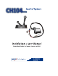
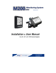
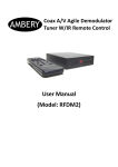
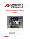
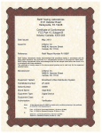
1
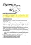
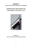
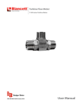
Control System Installation & User Manual CH103xx Jet Drive Control for Yanmar Engines MBW Technologies, LLC Email: [email protected] Phone: (267) 932.8573 x340 www.mbwtech.com CH103xx Jet Drive Control - Installation / User Manual MBW Technologies, LLC (2 – Year) Limited Warranty Electronic Modules and Displays MBW Technologies, LLC (“MBW”) warrants its Electronic Module and Display products to be free from defects in materials and workmanship for a period of two (2) years from the date of shipment by MBW. Within this period, MBW will, at its sole option, repair or replace any Electronic Module or Display that fails in normal use and is returned to MBW (freight prepaid) within the warranty period. MBW is not responsible for charges connected with the removal of such product or reinstallation of replacement or repaired parts. This warranty does not cover failures due to abuse, misuse, accident, faulty installation or unauthorized alteration or repairs. THE EXPRESS WARRANTY SET FORTH ABOVE IS IN LIEU OF ALL OTHER WARRANTIES, EXPRESS OR IMPLIED, INCLUDING BUT NOT LIMITED TO THE IMPLIED WARRANTIES OF MERCHANTABILITY AND FITNESS FOR A PARTICULAR PURPOSE. Statements made by any person, including representatives of MBW, which are inconsistent or in conflict with the terms of this Limited Warranty, shall not be binding upon MBW unless reduced to writing and approved by a manager of MBW. IN NO EVENT SHALL MBW BE LIABLE FOR ANY INCIDENTAL, SPECIAL, INDIRECT, OR CONSEQUENTIAL DAMAGES, WHETHER RESULTING FROM THE USE, MISUSE OR INABILITY TO USE THIS PRODUCT OR FROM DEFECTS IN THE PRODUCT. Some states do not allow the exclusion of incidental or consequential damages, so the above limitation may not apply to you. MBW retains the exclusive right to repair or replace the electronic module or display or offer a full refund of the purchase price at its sole discretion. SUCH REMEDY SHALL BE YOUR SOLE AND EXCLUSIVE REMEMDY FOR ANY BREACH OF WARRANTY. MBW Technologies, LLC (1 – Year) Limited Warranty Cables and Connectors MBW Technologies, LLC (“MBW”) warrants its Electrical Cable and Connector products to be free from defects in materials and workmanship for a period of one (1) year from the date of shipment by MBW. Within this period, MBW will, at its sole option, repair or replace any electrical cable or connector that fails in normal use and returned to MBW (freight prepaid) within the warranty period. MBW is not responsible for charges connected with the removal of such product or reinstallation of replacement or repaired parts. This warranty does not cover failures due to abuse, misuse, accident, faulty installation or unauthorized alteration or repairs. THE EXPRESS WARRANTY SET FORTH ABOVE IS IN LIEU OF ALL OTHER WARRANTIES, EXPRESS OR IMPLIED, INCLUDING BUT NOT LIMITED TO THE IMPLIED WARRANTIES OF MERCHANTABILITY AND FITNESS FOR A PARTICULAR PURPOSE. Statements made by any person, including representatives of MBW, which are inconsistent or in conflict with the terms of this Limited Warranty, shall not be binding upon MBW unless reduced to writing and approved by a manager of MBW. IN NO EVENT SHALL MBW BE LIABLE FOR ANY INCIDENTAL, SPECIAL, INDIRECT, OR CONSEQUENTIAL DAMAGES, WHETHER RESULTING FROM THE USE, MISUSE OR INABILITY TO USE THIS PRODUCT OR FROM DEFECTS IN THE PRODUCT. Some states do not allow the exclusion of incidental or consequential damages, so the above limitation may not apply to you. MBW retains the exclusive right to repair or replace the cable or connector or offer a full refund of the purchase price at its sole discretion. SUCH REMEDY SHALL BE YOUR SOLE AND EXCLUSIVE REMEMDY FOR ANY BREACH OF WARRANTY. Warranty Return Procedure: To obtain warranty service, contact MBW Technical Support Department at (267) 932-8573 x341 or email [email protected] to describe problem and determine appropriate action. NMEA 2000® is a registered trademark of the National Marine Electronics Association. 2 Copyright 2010 MBW Technologies, LLC All Rights Reserved CH103xx Jet Drive Control – Installation / User Manual Table of Contents Product Overview ..................................................................................................... 4 Components ................................................................................................................. 4 System Diagram ......................................................................................................... 5 Installing the System................................................................................................ 6 System Operation ...................................................................................................... 8 Start-in-Gear Protection ......................................................................................... 8 System Calibration .................................................................................................... 9 Technical Specifications ......................................................................................... 9 EM103 Module ....................................................................................................................... 9 CH103 Data Transmitted ....................................................................................... 9 Copyright 2010 MBW Technologies, LLC All Rights Reserved 3 CH103xx Jet Drive Control - Installation / User Manual Product Overview The CH103xx Series Product is designed as a Plug ‘N’ Play Throttle and “Thrust” Control for Jet Drive applications using Yanmar Electronic Engines. The system provides single lever electronic throttle operation and independent mechanical shift/bucket operation. Components 1000066 CH; Livorsi, Jet, SE, Black, ETP, ESSA, no detent 1 per engine 1000016 Switch; N.O. , momentary, Grn LED, w/connector 1 per engine CM10002 Harness; Devicenet, 2’ As needed CM10003 Harness; Devicenet, 3’ As needed CM10006 Harness; Devicenet, 6’ As needed CM10009 Harness; Devicenet, 9’ As needed CM10012 Harness; Devicenet, 12’ As needed CM10016 Harness; Devicenet, 16’ As needed CM10020 Harness; Devicenet, 20’ As needed CM10030 Harness; Devicenet, 30’ As needed CM10060 T; Devicenet As needed EM103SE EM; CH, Jet Drive Sport Style, Yanmar Electronic, SE 1 per engine EM103DE EM; CH, Jet Drive Sport Style, Yanmar Electronic, DE 1 per system MN10010-XX Manual, User/Installation, CH103 series 1 per engine MN10013-XX Mounting Template, CH103 series 1 per engine 1000016 – Select Switch 1000066 Throttle Head EM103xx – Electronic Module 4 Copyright 2010 MBW Technologies, LLC All Rights Reserved CH103xx Jet Drive Control – Installation / User Manual System Diagram Copyright 2010 MBW Technologies, LLC All Rights Reserved 5 CH103xx Jet Drive Control - Installation / User Manual Installing the System WARNING: This control WILL NOT provide start-in-gear protection meeting USG requirements of “33 CFR Part 183, Subpart L.” Ensure gear/thrust control is in neutral before starting engine. Making the Connections Each connector end has a label identifying the connection location. Match the labels with connecting device. In most cases the connector fits in one and only one mating connector. The supply power MUST be OFF when interconnecting the system. The EM103 module must be calibrated to the mating throttle head. The CH103 system is supplied from the factory calibrated to the supplied throttle head. Should the EM103 module be mated with a new throttle head, recalibration is required. See System Calibration section for details. 6 Recommended order: 1. Verify the battery / battery switch connections to each engine per the engine installation diagram. (Refer to engine manufacturer installation manual.) Verify engines are bonded to battery return (-) and that battery banks are tied to battery return. Verify engine blocks are connected battery bank ground. 2. Locate placement area for throttle head. Use supplied template (MN10013) for proper mounting. 3. Locate placement area for EM103 module. Use supplied template (MN10013) for proper mounting. 4. Locate placement area for throttle select switch. Mount using 5/8” dia. Hole. ® 5. Locate Yanmar NMEA 2000 network. Find appropriate location to install a network ‘T’. Connect EM103 module to network using certified network harnessing and ‘T’. 6. Connect throttle select switch to EM103 module. (2- 2pin DTM connectors) 7. Connect EM103 module to throttle head via: 1 - Packard 6 pin , 1 - Deutsch 3 pin connector. 8. Locate gear connector on the Yanmar Control System Interface Module. Jumper the Neutral Start Protect input, pin 5 to pin 11. If the mechanical thrust system has a NSP connection, connect pins 5 & 11 to this connection. These connections are necessary for the Yanmar engine to start. Copyright 2010 MBW Technologies, LLC All Rights Reserved CH103xx Jet Drive Control – Installation / User Manual After all controls and system components have been mounted and connected, the system must be setup to agree with the engines, transmissions and operator preferences. Reference Yanmar Electronic Control Operational Manual for details. CH103xx Series Interconnect Copyright 2010 MBW Technologies, LLC All Rights Reserved 7 CH103xx Jet Drive Control - Installation / User Manual System Operation For single station applications, the control will auto select when the system is powered and the throttle lever is less than 2% throttle. For dual station applications station select will occur when throttle lever is less than 2% and select switch for desired station is pressed. (Green lamp active when station selected.) If the control is not selected the select lamp will flash. The Yanmar System will allow the engine to start if the throttle head is not selected but will not allow the engine to throttle up until the control is selected. If the select lamp is flashing simply move the control to the idle position. The select lamp will stop flashing and indicate a steady green indication. The control is now selected and operational. Since the gear lever is connected via a mechanical cable to the thrust or “bucket” system, its operation is independent of the throttle control. When first operating the system be careful to establish forward and aft (reverse) operation. The EM103 communicates to the Yanmar Control Interface Module and will lock-out engine start when the throttle lever is requesting a throttle > 5% and the station is selected. Because this system is connected to a mechanical “thrust” system the gear information is available on the Yanmar control network. As a result, the EM103 will communicate an “in-gear” message to the Yanmar Control Module when the engine is started. This is necessary to allow the Yanmar Electronic Engine to properly calculate and display engine fuel flow data. Start-in-Gear Protection The Yanmar Control System provides a connection for start-in-Gear protection. This connection is made in the control system engine harness. (See system diagram for details.) Since the gear control of this system is a “bucket” the notion of a neutral position is difficult to ascertain. Therefore, the Yanmar Control System NSP must jumpered to allow the Yanmar engine to start. Jumper the Neutral Start Protect input of the Yanmar Control Module (pin 5 to pin 11). If the mechanical thrust system has a NSP connection, connect pins 5 & 11 to this connection. If the Jet Drive application has a mechanical switch connection for the neutral position it should be connected. The CH103 control will not allow the engine to start if the throttle is > 5% throttle and the control is selected. Note: The CH103 does not evaluate the “bucket” position and prevent the engine from starting. 8 Copyright 2010 MBW Technologies, LLC All Rights Reserved CH103xx Jet Drive Control – Installation / User Manual System Calibration To calibrate the EM103xx module with the mating throttle head, perform the following steps. 1. 2. 3. 4. 5. 6. 7. With the control powered off, move the gear lever to the full forward position; the throttle lever to idle. Power the system, while pressing and holding the select switch. The control is now in the calibrate mode. Select lamp “Off” Move the throttle lever to the wide open throttle position. Press the select switch to enter the position data of the throttle lever. The green lamp on the select switch will flash momentarily when data is entered. Move the throttle lever to the idle position. Press the select switch to enter the position data of the throttle lever. The green lamp on the select switch will flash momentarily when data is entered. Power the system off and back on. The control is now calibrated. Verify calibration by viewing the %Throttle display on the i5601E display. The display should read 100% when the throttle lever is a WOT and 0% at idle. Technical Specifications EM103 Module Operating Voltage 6 to 16 VDC Operating Temperature -18C to +77C Storage Temperature -40C to +85C Power Consumption - operating 250mA @ 12VDC (w/display) Power Consumption – power down <100uA Vibration ABYC P-24 Communication NMEA 2000® Humidity Test 100 Hours +77C @ 90-95% Rel. Humidity Transient Voltage Test SAE J1113-12 Protection IP67 Corrosion / Salt Spray 300 hrs per ASTM B117 EMI Emissions ABYC P-24 EMI Immunity ABYC P-24 Dimensions (base unit without harness) 117mm x 115mm x 35mm (4.63” x 4.50” x 1.38”) CH103 Data Transmitted Engine Throttle Gear Yanmar proprietary Yanmar proprietary Copyright 2010 MBW Technologies, LLC All Rights Reserved 9 CH103xx Jet Drive Control - Installation / User Manual 10 Copyright 2010 MBW Technologies, LLC All Rights Reserved CH103xx Jet Drive Control – Installation / User Manual P/N: MN10010-00 MBW Technologies, LLC 2080 Detwiler Rd, Suite 1 Harleysville, PA 19438 Tech Support: (267) 932-8573 x341 Fax (267) 284-1336 Email: [email protected] Email: [email protected] OR Contact your local Yanmar Dealer Copyright 2010 MBW Technologies, LLC All Rights Reserved 11