1
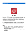
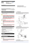
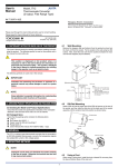
DP-D Series AC/DC Laboratory Power Supply User's Manual V3 Version 10.07.2015 1. Use of Operation Manual Please read through and understand this Operation Manual before operating the product. After reading, always keep the manual nearby so that you may refer to it as needed. When moving the product to another location, be sure to bring the manual as well. Calibration noti fication We notify that the instruments included in this manual are in compliance with the features and speci fications as stated in this manual. Before shipment, the instrument has been calibrated in factory. The calibration procedures and standards are compliant to the national regulations and standards for electronic calibration. Warranty We guarantee that the instrument has been passed strict quality check. We warrant our instrument’s mainframe and accessories in materials within the warranty period of one year. We guarantee the free spare parts for products which are approved defective in this period. To get repair service, please contact with your nearest sales and service of fice. We do not provide any other warranty items except the one being provided by this summary and the warranty statement. The warranty items include but not being subjected to the hinted guarantee items related to tradable characteristics and any particular purpose. We will not take any responsibility in cases regarding to indirect, particular and ensuing damage, such as modi fications to the circuit and functions by the users, repairing or component replacement by the users, or damage during transportation. For product improvement, the speci fications are subject to change without prior notice. 1.1 Safety Instructions This chapter contains important safety instructions that you must follow when operating the instrument and when keeping it in storage. Read the following before any operation to insure your safety and to keep the best condition for the instrument. Safety Symbols The following safety symbols may appear in this manual or on the instrument: WARNING Identi fies conditions or practices that could result in injury or loss of life. CAUTION Identi fies conditions or practices that could result in damage to the instrument or to other properties. DANGER High voltage ATTENTION Refer to the manual Protective conductor terminal Earth (Ground) terminal 1.2 Safety Guidelines General The power supply can be used only by quali fied personnel. Do not connect any load to the power supply before it's turned on. Make sure to disconnect the load before shutting down the power supply. Not following this instruction may cause damages to the power supply which are not under warranty. Before turning on the power supply, make sure the chassis are properly grounded. Removing grounding or improper GND terminal connection may cause electrical shock. Do not use this power supply on life support system or other systems with similar requirements. Do not use this power supply near water. Do not operate or touch this power supply with wet hands. Do not open the casing of the power supply when it is connected to AC mains. The max. output voltage of the power supply may be over 60VDC, never touch the metal contact parts of the output terminals while the output is ON. Do not use the power supply in an atmosphere which contains sulfuric acid mist or other substances which cause corrosion to metal. Do not use the power supply in a dusty place or a highly humid place as such will cause power supply reliability degradation and instrument failures. Install the power supply in a place free from vibration. Install the power supply in a place with ambient temperature in range of -10~70 degree celsius. Note that the power supply operation may become unstable if it is operated in an ambient temperature exceeding the range of 0~40 degree Celsius. If you are running inductive load like magnetic coils, DC motors etc. make sure to change the voltage/current slowly, and NEVER turn the power supply on or off with a inductive load connected. NOTE: Only important for DP-D without reverse current protection option. Power supply AC input voltage: refer to input label on rear panel. Connect the protective grounding conductor of the AC power cord to an earth ground to avoid electrical shock. Fuse The DP-D Series are Protected with an automatic fuse. To reset the fuse, disconnect AC power for 5 minutes. Make sure the cause of fuse blowout is fixed before fuse reset/replacements. 2. General Knowledge The DP-D power supply can supply voltage and current in constant voltage (CV) or constant current (CC) mode within the rated output range. This allows continuous switching from constant current to constant voltage modes in response to the load change. In CV mode, a regulated output voltage is provided. The output voltage remains constant as the load increases while the output current changes in response to the load changes, untill the preset current limit point is reached. At that point, the output current becomes constant and the output voltage drops in proportion to the further increases in load. The pint is indicated by the front panel LED indicators. Similarly in CC mode switching from CC to CV mode automatically occurs from a decrease of the load. A regulated output current is provided. The output current remains constant as the load decreases while the output voltage changes in response to the load changes. 2.1 Application of Capacitive Load Note: Only needed for DP-D devices without Reverse Current protection (Optional). If the power supply is connected to a big capacitive load, it always causes interferences to the output voltage in a power supply. To solve this problem, connect a power resistor in parallel to the output terminals of the power supply. At the same time, connect a diode in serial between output terminals and the load. 2.2 Application of Inductive Load Note: Only needed for DP-D devices without Reverse Current protection (Optional). If an inductive load is connected to the power supply, it will cause a reverse polarity induction electric impulse when the power supply is turned on or off, or when changing the output voltage / polarity. The pulse caused by an inductive load will also affect the power supply, especially when the pulse has the same polarity with the output of power supply. To avoid effect or damage to the power supply, connect a diode in serial between the output terminals of power supply and the load. At the same time, connect a power resistor and a capacitor in parallel to the load to make a R-C filter circuit, which will signi ficantly decrease generation of the impulse. 2.3 Application of Battery Load Note: Only needed for DP-D devices without Reverse Current protection (Optional). If using the DP-D for charging a battery, it is recommended to connect a diode between the power supply and the battery. 2.4 Application of Pulse Load If the peak current of a pulse load such as motor, bulb, DC-DC or DC-AC converter module is nearly the rated current of the power supply, it can cause voltage drop or instability to the output. A basic solution is to connect a inductor in serial between the power supply and the load. If the pulse circuit has a small pulse width or low peak current, another solution is to additionaly connect a capacitor with large capacity. A reference for choosing the capacity of a capacitor is: 1000uF capacity to 1A current. 2.5 Application of Load with Reverse Polarity Current Note: Only needed for DP-D devices without Reverse Current protection (Optional). If the power supply is connected to a load that can cause reverse polarity current to the power supply output, the output voltage will become unstable. A solution is to connect a diode in serial between the output terminal and the load. At the same time, connect a discharge resistor in parallel to the load. If the reverse polarity current is a peak surge, connect a electrolytic capacitor in parallel to the load. 2.6 Switch If a mechanic switch is used to connect or disconnect the power supply output, electric discharge will occur during switching. This may cause instability to the output. To prevent such situations, connect a RC circuit to the switch contact point. 3. Installation and Connection 1. The power supply will generate heat during operation. Before operation, the power supply should be placed in an environment with good ventilation. Avoid places of great heat, high humidity & temperature or heavy dust. 2. Allows suf ficient ventilation space at the front and rear panels. A ventilation distance between the power supply and other equipments should be at least 300mm. Avoid overlapping with other equipments. 3. The magnetic field generated from the power supply can have in fluence to nearby devices. Please place devices which are sensitive to magnetic field away from the power device. 4. Choose suitable AC input wire according to the rated power of the power supply. 5. Choose suitable DC output wire according to rated power of the power supply to connect the load. 4. Panel Introduction No. 1 2 3 4 5 6 7 8 9 Name Voltage Current C.C indicator C.V indicator Output indicator OV Led OL Led OT Led Current set 10 Voltage set 11 12 13 14 15 Preset button Output ON/OFF Power switch PR indicator FI Indicator Description Display the output voltage Displays the output current Constant Curent mode indicator Constant Voltage mode indicator Output ON indicator Over Voltage protection ON Overload protection ON Over temperature protection ON If the power supply is in CC mode (or current limit mode), tune this knob to set the current value. If the power supply is in CV mode, tune this knob to set the over current limit value If the power supply is in CV mode, tune this knob to set the output voltage value. If the power supply is in CC mode, tune this knob to set the over voltage limit value Press this button to set voltage and current preset Use this switch to turn on or off the output Use this switch to turn on or off the power supply PRESET Mode ON Voltage / Current fine tune mode 5. Operation Instructions 5.1 Device Check NOTE: The device check should only be performed for troubleshooting purposes. 1. DO NOT connect any load to the power supply during the device check. 2. Tune the CURRENT knob clockwise to the maximum and the VOLTAGE knob anticlockwise to 0V. 3. Use the POWER switch to turn on the power supply. 4. Press OUTPUT ON button to get the power supply in working mode: C.V indicator lights on, while C.C indicator lights off. 5. Tune the VOLTAGE knob clockwise to increase the output voltage from 0V to the max.rated value. The voltmeter will display max. voltage value. 6. Press OUTPUT button again to turn off the output. Recheck if the output is OFF. 7. Tune the CURRENT knob anti-clockwise to the minimum, while tune the VOLTAGE knob clockwise to the maximum. 8. Connect a wire between terminals “OUT+” and “OUT-”. The output wire must be able to sustain max. rated current of the power supply for 10 seconds. 9. Press OUTPUT button to turn on the power supply once again. C.C indicator will switch on while C.V indicator will switch off. 10. Tune the CURRENT knob clockwise, the output current will start from 0A to the max. rated value. 11. Press OUTPUT button again to turn off the output. Then take off all connecting wires. 5.2 Voltage and Current (PRESET) NOTE: Connect the load always before turning on the output, but after turning on the power supply. Always wait after switching on the DP-D until the switch-on pulse is discharged (See voltage indicator), before making any adjustments or connect a load. 1. Press the POWER button to turn on the power supply. 2. Make sure the OUTPUT is OFF. 3. Press PRESET button, the display meter displays the preset voltage and current. Tune CURRENT and VOLTGE knob to set values. 4. Press the PRESET button to save the values. 5. Conned to load. 6. Press OUTPUT button to turn on output. 7. Press the PRESET button to activate the values saved before. 5.3 CV Constant Voltage Operation NOTE: Connect the load always before turning on the output, but after turning on the power supply. Always wait after switching on the DP-D until the switch-on pulse is discharged (See voltage indicator), before making any adjustments or connect a load. 1. Press the POWER button to turn on the power supply and make sure the output is OFF. 2. Press the PRESET button to set the voltage and max. current. 3. Recheck if the output is OFF. 4. Connect to load. 5. Press OUTPUT button to turn on output. 6. The power supply outputs voltage as per setting value. The output current value changes according to changes of load consumption. Should the output current reach the max. current vailue set before, the device automatically switches to C.C mode and adjusts the voltage. 5.4 Constant Current Operation NOTE: Connect the load always before turning on the output, but after turning on the power supply. Always wait after switching on the DP-D until the switch-on pulse is discharged (See voltage indicator), before making any adjustments or connect a load. 1. 2. 3. 4. 5. 6. Press the POWER button to turn on the DP-D, make sure the output is OFF. Press the PRESET button to set the max. voltage and current. Recheck if the output is OFF. Connect to load. Press OUTPUT button to turn on output. The power supply outputs current as per setting value. The output voltage value changes according to changes of load consumption. Should the output voltage reach the max. voltage value set before, the device automatically switches to C.V mode and adjusts the current. 5.5 Remote Sensing Operation The power supply is designed with remote sensing terminals, which can read voltage th the load accurately. Refer to below figure on how to connect the load to remote sensing terminals. Set the switch on the back panel to “EXT” when using remote sensing function, or set to “INT” when not using this option. WARNING: If using a switch between the load and the power supply, refer to below figure for connection and make sure the remote sensing wires and the load connecting wire can be switched on or off simultaneously. Otherwise, it will cause damage to the power supply. 6. Maintenance The following instructions are for use by quali fied personnel only. To avoid electrical shock, do not perform any servicing other than contained in the operating instructions unless you are quali fied to do so. 1. Inspect the instrument at regular intervals so that it maintains its initial performance for a long time. 2. Check the input power cord for damage. Check the terminal screws and binding posts for loosening. 3. Remove dust from the inside of the casing and ventilation holes of the cover by using compressed air or a vacuum cleaner. 6.1 Cleaning 1. Before cleaning, disconnect the AC mains. 2. To clean the power supply, use a soft cloth dampened in a solution of mild detergent and water. Do not spray cleaner directly onto the instrument, since it may leak into the case and cause damage. 3. Do not use chemicals containing benzene, benzene, toluene, xylene, acetone, or similar solvents. 4. Do not use abrasive cleaners on the instrument.