1
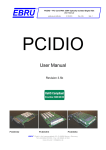
Licel Transient Recorder and
Ethernet-Controller
Programming Manual
Licel GmbH
February 26, 2013
1
CONTENTS
Contents
1 Program function and Structure
1.1 Introduction . . . . . . . . . . . . . . . .
1.1.1 Description . . . . . . . . . . . .
1.1.2 Operation Principles . . . . . . .
1.1.3 Hardware Requirements . . . . .
1.1.4 Further References . . . . . . .
1.2 Program Organization . . . . . . . . . .
1.2.1 Structure . . . . . . . . . . . . .
1.2.2 Modules . . . . . . . . . . . . . .
1.2.3 licel nidaq/licel re . . . . . . . . .
1.2.4 licel tcpip . . . . . . . . . . . . .
1.2.5 licel tr/licel tr tcpip . . . . . . . .
1.2.6 licel util . . . . . . . . . . . . . .
1.2.7 APD functions . . . . . . . . . .
1.2.8 PMT functions . . . . . . . . . .
1.2.9 Timing functions . . . . . . . . .
1.2.10 Security functions . . . . . . . .
1.2.11 Power Meter . . . . . . . . . . .
1.2.12 Bore Alignment . . . . . . . . . .
1.2.13 Function arguments . . . . . . .
1.2.14 Timing Parameter explanation .
1.2.15 Low Level Commands . . . . . .
1.3 Memory organization . . . . . . . . . . .
1.4 Raw Data to Physical Value Conversion
1.5 Acquisition Low Level Description . . . .
1.6 Network security . . . . . . . . . . . . .
.
.
.
.
.
.
.
.
.
.
.
.
.
.
.
.
.
.
.
.
.
.
.
.
.
.
.
.
.
.
.
.
.
.
.
.
.
.
.
.
.
.
.
.
.
.
.
.
.
.
.
.
.
.
.
.
.
.
.
.
.
.
.
.
.
.
.
.
.
.
.
.
.
.
.
.
.
.
.
.
.
.
.
.
.
.
.
.
.
.
.
.
.
.
.
.
.
.
.
.
.
.
.
.
.
.
.
.
.
.
.
.
.
.
.
.
.
.
.
.
.
.
.
.
.
.
.
.
.
.
.
.
.
.
.
.
.
.
.
.
.
.
.
.
.
.
.
.
.
.
.
.
.
.
.
.
.
.
.
.
.
.
.
.
.
.
.
.
.
.
.
.
.
.
.
.
.
.
.
.
.
.
.
.
.
.
.
.
.
.
.
.
.
.
.
.
.
.
.
.
.
.
.
.
.
.
.
.
.
.
.
.
.
.
.
.
.
.
.
.
.
.
.
.
.
.
.
.
.
.
.
.
.
.
.
.
.
.
.
.
.
.
.
.
.
.
.
.
.
.
.
.
.
.
.
.
.
.
.
.
.
.
.
.
.
.
.
.
.
.
.
.
.
.
.
.
.
.
.
.
.
.
.
.
.
.
.
.
.
.
.
.
.
.
.
.
.
.
.
.
.
.
.
.
.
.
.
.
.
.
.
.
.
.
.
.
.
.
.
.
.
.
.
.
.
.
.
.
.
.
.
.
.
.
.
.
.
.
.
.
.
.
.
.
.
.
.
.
.
.
.
.
.
.
.
.
.
.
.
.
.
.
.
.
.
.
.
.
.
.
.
.
.
.
.
.
.
.
.
.
.
.
.
.
.
.
.
.
.
.
.
.
.
.
.
.
.
.
.
.
.
.
.
.
.
.
.
.
.
.
.
.
.
.
.
.
.
.
.
.
.
.
.
.
.
.
.
.
.
.
.
.
.
.
.
.
.
.
.
.
.
.
.
.
.
.
.
.
.
.
.
.
.
.
.
.
.
.
.
.
.
.
.
.
.
.
.
.
.
.
.
.
.
.
.
.
.
.
.
.
.
.
.
.
.
.
.
.
.
.
.
.
.
.
.
.
.
.
.
.
.
.
.
.
.
.
.
.
.
.
.
.
.
.
.
.
.
.
.
.
.
.
.
.
.
.
.
.
.
.
.
.
.
.
.
.
.
.
.
.
.
.
.
.
.
.
.
.
.
.
.
.
.
.
.
.
.
.
.
.
.
.
.
.
.
.
.
.
.
.
.
.
.
.
.
.
.
.
.
.
.
.
.
.
.
.
.
.
.
.
.
.
.
.
.
.
.
.
.
.
.
.
.
.
.
.
.
.
.
.
.
.
.
.
.
.
.
.
.
.
.
.
.
.
.
.
.
.
.
.
.
.
.
.
.
.
.
.
.
.
.
.
.
.
.
.
.
.
.
.
.
.
.
.
.
.
.
.
.
.
.
.
.
.
.
.
.
.
.
.
.
.
.
.
.
.
.
.
.
.
.
.
.
.
.
.
.
.
.
.
.
.
.
.
.
.
.
.
.
.
.
.
.
.
.
.
.
.
.
.
.
.
.
.
.
.
.
.
.
.
.
.
.
.
.
.
.
.
.
.
.
.
.
.
.
.
.
.
.
.
.
.
.
.
.
.
.
.
.
.
.
.
.
.
.
.
.
.
.
.
.
.
.
.
.
.
.
.
.
.
.
.
.
.
.
.
.
.
.
.
.
.
.
.
.
.
.
.
.
.
.
.
.
.
.
.
.
.
.
.
5
5
5
6
6
6
6
6
6
6
7
8
12
13
13
13
14
14
15
15
19
20
21
22
23
24
2 Installation
2.1 Ethernet software . . . . . . . . . . . . .
2.1.1 Required software . . . . . . . .
2.2 Windows - DIO-32HS . . . . . . . . . .
2.2.1 Required software . . . . . . . .
2.2.2 NI-DAQ-Setup . . . . . . . . . .
2.2.3 Interface card installation . . . .
2.2.4 Verification . . . . . . . . . . . .
2.3 Linux - PCI-DIO-32HS . . . . . . . . . .
2.3.1 Kernel preparation . . . . . . . .
2.3.2 Necessary Files . . . . . . . . .
2.3.3 Driver tests and card installation
2.3.4 Changes to /etc/modules.conf . .
2.3.5 Changes to /etc/rc.d/rc.local . . .
2.3.6 Directory structure . . . . . . . .
2.3.7 LabView + comedi . . . . . . . .
2.4 Software installation . . . . . . . . . . .
.
.
.
.
.
.
.
.
.
.
.
.
.
.
.
.
.
.
.
.
.
.
.
.
.
.
.
.
.
.
.
.
.
.
.
.
.
.
.
.
.
.
.
.
.
.
.
.
.
.
.
.
.
.
.
.
.
.
.
.
.
.
.
.
.
.
.
.
.
.
.
.
.
.
.
.
.
.
.
.
.
.
.
.
.
.
.
.
.
.
.
.
.
.
.
.
.
.
.
.
.
.
.
.
.
.
.
.
.
.
.
.
.
.
.
.
.
.
.
.
.
.
.
.
.
.
.
.
.
.
.
.
.
.
.
.
.
.
.
.
.
.
.
.
.
.
.
.
.
.
.
.
.
.
.
.
.
.
.
.
.
.
.
.
.
.
.
.
.
.
.
.
.
.
.
.
.
.
.
.
.
.
.
.
.
.
.
.
.
.
.
.
.
.
.
.
.
.
.
.
.
.
.
.
.
.
.
.
.
.
.
.
.
.
.
.
.
.
.
.
.
.
.
.
.
.
.
.
.
.
.
.
.
.
.
.
.
.
.
.
.
.
.
.
.
.
.
.
.
.
.
.
.
.
.
.
.
.
.
.
.
.
.
.
.
.
.
.
.
.
.
.
.
.
.
.
.
.
.
.
.
.
.
.
.
.
.
.
.
.
.
.
.
.
.
.
.
.
.
.
.
.
.
.
.
.
.
.
.
.
.
.
.
.
.
.
.
.
.
.
.
.
.
.
.
.
.
.
.
.
.
.
.
.
.
.
.
.
.
.
.
.
.
.
.
.
.
.
.
.
.
.
.
.
.
.
.
.
.
.
.
.
.
.
.
.
.
.
.
.
.
.
.
.
.
.
.
.
.
.
.
.
.
.
.
.
.
.
.
.
.
.
.
.
.
.
.
.
.
.
.
.
.
.
.
.
.
.
.
.
.
.
.
.
.
.
.
.
.
.
.
.
.
.
.
.
.
.
.
.
.
.
.
.
.
.
.
.
.
.
.
.
.
.
.
.
.
.
.
.
.
.
.
.
.
.
.
.
.
.
.
.
.
.
.
.
.
.
.
.
.
.
.
.
.
.
.
.
.
.
.
.
.
.
.
.
.
.
.
.
.
.
.
.
.
.
.
.
.
.
.
.
.
.
.
.
.
.
.
.
.
.
26
26
26
26
26
26
26
27
27
27
28
28
28
28
28
29
29
3 C - Example Programs
3.1 The script . . . . . . . . . . . . . . . . .
3.2 start . . . . . . . . . . . . . . . . . . . .
3.3 shot . . . . . . . . . . . . . . . . . . . .
3.4 readout . . . . . . . . . . . . . . . . . .
3.5 Example Program Configuration File . .
3.6 File format . . . . . . . . . . . . . . . . .
3.7 SampleAcquis for Ethernet Applications
3.8 Network management utilities . . . . . .
3.8.1 Getting Started . . . . . . . . . .
3.8.2 Set Fixed IP Address . . . . . .
3.8.3 Activate DHCP Mode . . . . . .
.
.
.
.
.
.
.
.
.
.
.
.
.
.
.
.
.
.
.
.
.
.
.
.
.
.
.
.
.
.
.
.
.
.
.
.
.
.
.
.
.
.
.
.
.
.
.
.
.
.
.
.
.
.
.
.
.
.
.
.
.
.
.
.
.
.
.
.
.
.
.
.
.
.
.
.
.
.
.
.
.
.
.
.
.
.
.
.
.
.
.
.
.
.
.
.
.
.
.
.
.
.
.
.
.
.
.
.
.
.
.
.
.
.
.
.
.
.
.
.
.
.
.
.
.
.
.
.
.
.
.
.
.
.
.
.
.
.
.
.
.
.
.
.
.
.
.
.
.
.
.
.
.
.
.
.
.
.
.
.
.
.
.
.
.
.
.
.
.
.
.
.
.
.
.
.
.
.
.
.
.
.
.
.
.
.
.
.
.
.
.
.
.
.
.
.
.
.
.
.
.
.
.
.
.
.
.
.
.
.
.
.
.
.
.
.
.
.
.
.
.
.
.
.
.
.
.
.
.
.
.
.
.
.
.
.
.
.
.
.
.
.
.
.
.
.
.
.
.
.
.
.
.
.
.
.
.
.
.
.
.
.
.
.
.
.
.
.
.
.
.
.
.
.
.
.
.
.
.
.
.
.
.
.
.
.
.
.
.
.
.
.
.
.
.
.
.
.
.
.
.
.
.
.
.
.
.
.
.
.
.
.
.
.
.
.
.
.
.
.
.
.
.
.
.
.
.
.
.
.
.
.
.
.
.
.
.
.
.
.
.
.
.
.
.
.
.
.
.
.
.
.
29
30
30
30
30
30
31
33
33
33
34
34
3
CONTENTS
3.8.4 SecureModeEnable . . . . . . . . . . . . . . . . . . . . . . . . . . . . . . . . . . . . . . . 34
3.8.5 SecureModeDisable . . . . . . . . . . . . . . . . . . . . . . . . . . . . . . . . . . . . . . . 34
4 Appendix VB6/VB.net Programming
4.1 Sample applications . . . . . . .
4.1.1 Control Overview . . . . .
4.1.2 MultipleChannel . . . . .
4.1.3 PushModeDemo . . . . .
.
.
.
.
.
.
.
.
.
.
.
.
.
.
.
.
.
.
.
.
.
.
.
.
.
.
.
.
.
.
.
.
4
.
.
.
.
.
.
.
.
.
.
.
.
.
.
.
.
.
.
.
.
.
.
.
.
.
.
.
.
.
.
.
.
.
.
.
.
.
.
.
.
.
.
.
.
.
.
.
.
.
.
.
.
.
.
.
.
.
.
.
.
.
.
.
.
.
.
.
.
.
.
.
.
.
.
.
.
.
.
.
.
.
.
.
.
.
.
.
.
.
.
.
.
.
.
.
.
.
.
.
.
.
.
.
.
.
.
.
.
.
.
.
.
34
34
34
34
34
Program function and Structure
1
Program function and Structure
1.1
1.1.1
Introduction
Description
Currently the Transient Recorder can be controlled by two ways:
• Via a Ethernet interface. The Ethernet interface has then its own parallel bus interface to the Transient
Recorders.
• Via the parallel interface cards from National Instruments, this option is deprecated. It only works till WinXP. There is no driver support under NIDAQmx and this excludes Windows Vista Windows 7 as operating
systems.
The software to control the Licel Transient Recorder will
• Control one or more Transient Recorders
• Ensure software portability between different operating systems
• Readout the Transient Recorders at high data transfer rates.
The software for the Ethernet Controller will in addition control
• The APD module
• The PMT module
• The Trigger module
The following target systems are supported:
• LabVIEW from National Instruments
– WinXX, Linux
– Mac-OS
• NIDAQ-Library from National Instruments
– WinXX with MS Visual C
– WinXX with MS Visual Basic
• A COMEDI based Linux driver for gcc
• MS Visual C and gcc for the Ethernet Controller software.
• A Visual Basic/VB.net module for the Ethernet Controller software. This module is sold separately.
The software is able to:
• configure the Transient Recorders
• start the data acquisition
• stop the data acquisition
• query the Transient Recorder status
• readout the Transient Recorder
• convert the binary data to quantities with physical units.
The Ethernet based software additionally is able to:
• Set the PMT high voltage and read the PMT status.
• Set the APD high voltage, Activate the APD thermo electrical cooler and read the APD Status back.
• Set the delays on the trigger generator and to activate separately the trigger lines.
5
Program function and Structure
1.1.2
Operation Principles
The communication with the Transient Recorder is performed via a parallel bus using a hardware handshake.
The parallel bus is based on the digital I/O card family DIO-32HS supplied by National Instruments. For
the description of the bus timing refer to the user manual from National Instruments . The used protocol is
Level-Acq. This interface is also implemented internally between the Ethernet Controller and the Transient
Recorders.
1.1.3
Hardware Requirements
Operating environment
Card type
Required Slot
PC
Ethernet
deprecated
AT-DIO-32HS
PCI-DIO-32HS
DAQCard 6533
PXI 6533
Ethernet connector
Desktop-PC Win9xx
Win-NT
Notebook
PXI
1.1.4
ISA Slot short
PCI slot
PCMCIA slot
PXI slot
Further References
1. DIO-653x User Manual
2. NI-DAQ User Manual for PC Compatibles
3. NI-DAQ Function Reference Manual for PC Compatibles
4. LabVIEW Measurements Manual
1.2
Program Organization
1.2.1
Structure
The software has layered structure where the low-level routines are encapsulated in licel nidaq.c or
licel nidaq.bas. These routines access NI-DAQ. Under Linux the corresponding file is licel re.c. This
file calls the corresponding comedilib functions. Above this layer are licel tr.c or
licel tr.bas. At this layer the functional tasks are translated into low-level commands.
For the Ethernet Controller the basic communication routines are inside licel tcpip.cpp Above this level
are the licel tr tcpip.cpp. At this layer the functional tasks are translated into low-level ASCII commands.
Above this layer are the application functions.
show tmp
start
shot
readout
licel tr tcpip.(cpp/bas)
licel tr.(c/bas)
WinXX: licel nidaq.(c/bas)
Linux: licel re.c
DIO6533 cards (PCMCIA, PCI, PXI,AT)
1.2.2
Modules
1.2.3
licel nidaq/licel re
Network management
licel tcpip.(cpp/bas)
Ethernet
The licel nidaq.(c|bas)/licel re.c are used for the National Instruments interface cards and have
four routines inside:
6
Program function and Structure
/* Setup of the DIO card*/
int Initialize Board(short int iBoard)
Public Function InitializeBoard(iBoard As Integer) As Integer
/* Writing the commands to the TR*/
int WriteCommand(short int iBoard, short iCommand)
Public Function WriteCommand(iBoard As Integer, iCommand As Integer)
As Integer
/* Reading back information from the TR*/
int ReadArray( short int iBoard, unsigned short *piBuffer,
unsigned long ulCount)
Public Function ReadArray(iBoard As Integer, piBuffer() As Integer,
ulCount As Long) As Integer
/* Selection of TR group*/
int Select(short int iBoard, int hilow)
Public Function Select TR(iBoard As Integer, iDevice As Integer) As Integer
In general these routines do not need a customer tweaking, the only place where customization may be
useful is in InitializeBoard the AcqDelay can be changed between 0 (0ns) and 7 (700ns), which might help
if data transfer errors do occur (readout errors usually give variable readout while reading repetitive the same
dataset, if this happens it is the right time to contact Licel for help )
1.2.4
licel tcpip
openConnection open the connection to specified host at a specified port
SOCKET openConnection(const char* host, int port);
Public Function openConnection(ByVal sHost As String, ByVal iPort As
Integer) As TcpClient
open the connection to specified host at a specified port, stays silent if it fails
Public Function openConnection(ByVal sHost As String, ByVal iPort As
Integer, ByVal silent As Boolean) As TcpClient
openSecureConnection open the connection to specified host at a specified port when the access to the
Controller is Limited (see Network Security for details)
SOCKET openSecureConnection(const char* sHost, int iPort, const char*
connectionPasswd);
closeConnection close the specified connection
int closeConnection(SOCKET s);
Public Function closeConnection(ByVal client As TcpClient) As Integer
writeCommand write a string to the tcpconnection, append the terminating CRLF
int writeCommand(SOCKET s, const char* command);
Public Function writeCommand(ByVal client As TcpClient, ByVal command
As String) As Integer
readResponse Read a ASCII response from the Controller. Except for binary data transfer the Controller
response is a short string indicating whether the action could be performed or not. This response is terminated
by a CRLF. This routine will read till it encounters a CRLF or if the amount of chars would exceed maxLength.
int readResponse(SOCKET s, char* response, int maxLength,
int nTimeOutMillisec);
7
Program function and Structure
Public Function readResponse(ByVal client As TcpClient, ByRef response
As String, ByVal maxlength As Integer, ByVal nTimeoutMillisec As Integer)
As Integer
ReadArray Read a binary response from the Controller.
int ReadArray(SOCKET s, unsigned char *array, unsigned long points,
int nTimeOutMillisec);
Public Function ReadArray(ByVal client As TcpClient, ByRef Data()
As Byte, ByVal points As Long, ByVal nTimeOutMillisec As Integer)
1.2.5
licel tr/licel tr tcpip
There is a major difference in the programming model between the DIO-32 and the Ethernet version, the
Ethernet version first selects the Transient Recorder and all commands (issued later ) are addressed to this
Transient Recorder. There are separate functions available for tasks such as starting all Transient Recorders.
Before they can be called a list of Transient Recorders should be selected, the functions indicated by Multiple
in the function name, are used for these purposes.
Controller
Licel TCPIP ActivateDHCP activate the DHCP mode on the Controller
int Licel TCPIP ActivateDHCP(SOCKET s, int iPort, const char* passwd);
Public Function Licel TCPIP ActivateDHCP(ByVal client As TcpClient,
ByVal iPort As Integer, ByVal passwd As String) As Integer
Licel TCPIP SetIPParameter Configure the Controller for static IP configuration. Set the new IP address,
the basic port number, the subnet mask and the gateway
int Licel TCPIP SetIPParameter(SOCKET s, char* newHost, char* mask, int newPort,
char* gateway, char* passwd);
Public Function Licel TCPIP SetIPParameter(ByVal client As TcpClient,
ByVal newHost As String, ByVal mask As String, ByVal newPort As Integer,
ByVal gateway As String, ByVal passwd As String) As Integer
Licel TCPIP GetID Get the identification string from the Controller
int Licel TCPIP GetID(SOCKET s, char* buffer, int bufferLength);
Public Function Licel TCPIP GetID(ByVal client As TcpClient, ByRef buffer
As String, ByVal bufferLength As Integer) As Integer
Licel TCPIP GetCapabilities Get the available subcomponents of the Controller like:
TR
for controlling Transient Recorder
APD
for APD remote control
PMT
for PMT remote control
TIMER
for the trigger timing Controller
CLOUD
for Transient Recorder Controller cloud mode
BORE
Boresight alignment system
int Licel TCPIP GetCapabilities(SOCKET s, char* cap, int bufferLength);
Public Function Licel TCPIP GetCapabilities(ByVal client As TcpClient,
ByRef cap() As String, ByVal maxLength As Integer, ByRef validcap As Integer)
As Integer
Transient recorder
8
Program function and Structure
Licel TCPIP SelectTR Select a Transient Recorder for subsequent communication
int Licel TCPIP SelectTR(s, int TR);
Public Function Licel TCPIP SelectTR(ByVal client As TcpClient,
ByVal TR As Integer) As Integer
Licel TCPIP SelectMultipleTR Select a list of Transient Recorders for subsequent communication
int Licel TCPIP SelectMultipleTR(SOCKET s, int* TRList, int trNumber);
Public Function Licel TCPIP SelectMultipleTR(ByVal client As TcpClient,
ByVal TRList() As Integer, ByVal trNumber As Integer) As Integer
SetDiscriminatorLevel Set the discriminator level between 0 and 63
int HS Licel Set Discriminator Level(short int iDevice ,int iDiscrLevel);
Public Function HS Licel Set Discriminator Level(iDevice As Integer,
iDiscrLevel As Integer) As Integer
int Licel TCPIP SetDiscriminatorLevel(SOCKET s, int iDiscrLevel);
Public Function Licel TCPIP SetDiscriminatorLevel(ByVal client As TcpClient,
ByVal iDiscrLevel As Integer) As Integer
SetRange Change the input voltage range (20,100,500mV)
int HS Licel Set Range(iDevice,int iRange);
Public Function HS Licel Set Range(iDevice As Integer, iRange As Integer) As
Integer
int Licel TCPIP SetInputRange(SOCKET s, iRange);
Public Function Licel TCPIP SetInputRange(ByVal client As TcpClient,
ByVal iRange As Integer) As Integer
SetThresholdMode Set the scale of the discriminator level. In the low threshold mode the disciminator level
63 corresponds to 25mV while in the high threshold mode it corresponds to 100mV.
int HS Licel Set Threshold Mode(short int iDevice, int iMode);
Public Function HS Licel Set Threshold Mode(iDevice As Integer, iMode As
Integer) As Integer
int Licel TCPIP SetThresholdMode(SOCKET s, int iMode);
Public Function Licel TCPIP SetThresholdMode(ByVal client As TcpClient,
ByVal iMode As Integer) As Integer
Licel TCPIP GetTRTYPE Get various Transient Recorder parameter specification information
int Licel TCPIP GetTRTYPE(SOCKET s, unsigned long int * trfifoLength, int *
trSernum, int * trPCbits, int * trADCBits, float * trSamplingRate);
Licel TCPIP SetShotLimit Enable or Disable the 64k Shot acquisition mode
int Licel TCPIP SetShotLimit(SOCKET s, int mode);
Licel TCPIP SetSlaveMode Set the slave mode
int Licel TCPIP SetSlaveMode(SOCKET s);
Public Function Licel TCPIP SetSlaveMode(ByVal client As TcpClient)
As Integer
9
Program function and Structure
Licel TCPIP SetPushMode Activate the push mode for the currently selected Transient Recorder
int Licel TCPIP SetPushMode(SOCKET s, int shots,int dataset, int numberToRead,
int memory);
Public Function Licel TCPIP SetPushMode(ByVal client As TcpClient,
ByVal shots As Integer, ByVal dataset As Integer, ByVal numberToRead
As Integer, ByVal memory As Integer) As Integer
Licel TCPIP GetStatus Return the status information for one Transient Recorder
int HS Licel Get Status(short int iDevice,long int * iCycles, int * iMemory,
int * iAcq State, int * iRecording);
Public Function HS Licel Get Status(iDevice As Integer, iCycles As Integer,
iMemory As Integer, iAcq State As Integer, iRecording As Integer) As Integer
int Licel TCPIP GetStatus(SOCKET s, long int* iCycles, int* iMemory,
int* iAcq State, int* iRecording);
Public Function Licel TCPIP GetStatus(ByVal client As TcpClient,
ByRef shotNumber As Integer, ByRef lastMemory As Integer,
ByRef acquisitionState As Integer, ByRef recording As Integer) As Integer
ContinueAcquisition Continue the recording process without a new initialisation of the memory
int HS Licel Continue Acquisition(short int iDevice);
Public Function HS Licel Continue Acquisition(iDevice As Integer) As Integer
int Licel TCPIP ContinueAcquisition(SOCKET s);
Public Function Licel TCPIP ContinueAcquisition(ByVal client As TcpClient)
As Integer
Licel TCPIP MultipleContinueAcqusition Continue the recording process for the previously selected Transient Recorders without a new initialisation of the memory
int Licel TCPIP MultipleContinueAcqusition(SOCKET s);
Public Function Licel TCPIP MultipleContinueAcqusition(ByVal client
As TcpClient) As Integer
StopAcqusition Stop the recorder after the next received trigger.
int HS Licel Stop Acquisition(short int iDevice);
Public Function HS Licel Stop Acquisition(iDevice As Integer)As Integer
int Licel TCPIP Stop(SOCKET s);
Public Function Licel TCPIP StopAcqusition(ByVal client As TcpClient)
As Integer
Licel TCPIP MultipleStopAcqusition Stop the acquisition process for the previously selected Transient
Recorders with the next received trigger pulse
int Licel TCPIP MultipleStopAcqusition(SOCKET s);
Public Function Licel TCPIP MultipleStopAcqusition(ByVal client
As TcpClient) As Integer
ClearMemory Clear both memories (A and B) of the Transient Recorder
int HS Licel Clear Memory(short int iDevice);
Public Function HS Licel Clear Memory(iDevice As Integer) As Integer
int Licel TCPIP ClearMemory(SOCKET s);
Public Function Licel TCPIP ClearMemory(ByVal client As TcpClient)
As Integer
10
Program function and Structure
Licel TCPIP MultipleClearMemory Clear both memories (A and B) of the previously selected Transient
Recoders
int Licel TCPIP MultipleClearMemory(SOCKET s);
Public Function Licel TCPIP MultipleClearMemory(ByVal client As TcpClient)
As Integer
Licel TCPIP IncreaseShots Increase the shotnumber of the TR without adding data, this can be used to
make a fixed number of acquisitions based on the internal 4094 shot limit.
int Licel TCPIP IncreaseShots(SOCKET s, int shots);
StartAcqusition Start the acquisition process with a new initialization of the memory
int HS Licel Start Acquisition(short int iDevice);
Public Function HS Licel Start Acquisition(iDevice As Integer) As Integer
int Licel TCPIP Start(SOCKET s);
Public Function Licel TCPIP StartAcqusition(ByVal client As TcpClient)
As Integer
Licel TCPIP MultipleStart Start the acquisition process for the previously selected Transient Recorders with
a new initialization of the memory
int Licel TCPIP MultipleStartAcqusition(SOCKET s);
Public Function Licel TCPIP MultipleStart(ByVal client As TcpClient)
As Integer
SingleShot Acquire one shot
int HS Licel Single Shot(short int iDevice);
Public Function HS Licel Single Shot(iDevice As Integer) As Integer
int Licel TCPIP SingleShot(SOCKET s);
Public Function Licel TCPIP SingleShot(ByVal client As TcpClient) As Integer
WaitForReady Wait for the return of the Transient Recorder from the armed state. If the waiting time is longer
than the time specified by delay, then the Transient Recorder will return to the idle state with the next reading
of binary data.
int HS Licel Wait For Ready(short int iDevice, int imDelay);
Public Function HS Licel Wait For Ready(iDevice As Integer, imDelay As
Integer) As Integer
int Licel TCPIP WaitForReady(SOCKET s, imDelay);
Public Function Licel TCPIP WaitForReady(ByVal client As TcpClient,
ByVal delay As Integer) As Integer
Licel TCPIP MultipleWaitForReady Wait until all Transient Recorders return from the armed state
int Licel TCPIP MultipleWaitForReady(SOCKET s, imDelay);
Public Function Licel TCPIP MultipleWaitForReady(ByVal client As TcpClient,
ByVal delay As Integer) As Integer
Licel TCPIP ReadData Read binary data into a byte array. Transient recorder data is internally 16bits wide
so for every data point two bytes need to be fetched.
int Licel TCPIP ReadData(SOCKET s, int numberToRead, unsigned char* data);
Public Function Licel TCPIP ReadData(ByVal client As TcpClient,
ByVal numberToRead As Integer, ByRef data() As Byte) As Integer
11
Program function and Structure
GetDatasets/Read16bitwide Read binary datasets from a Transient Recorder
int HS Licel Read 16bit wide(short int iDevice, int iDataset, int iNumber,
int iMemory, unsigned short * uPortData);
Public Function HS Licel Read 16bit wide(iDevice As Integer, iDataset As
Integer, iNumber As Integer, iMemory As Integer, uPortData() As Integer)
int Licel TCPIP GetDatasets(SOCKET s, int iDevice, int iDataset, int iNumber,
int iMemory, unsigned char* data);
Public Function Licel TCPIP GetDatasets(ByVal client As TcpClient,
ByVal TR As Integer, ByVal dataset As Integer, ByVal numberToRead As Integer,
ByVal memory As Integer, ByRef data() As Byte) As Integer
1.2.6
licel util
Combine Analog Datasets Converts the LSW and the MSW read out data values from a 12 bit ADC Transient Recorder into an integer array containing the summed up analog values. The first trash element (due to
the data transmission scheme) is also removed.
void Licel Combine Analog Datasets(unsigned short * iLsw, unsigned short *
iMsw, int iNumber, unsigned long * lAccumulated, short * iClipping);
Public Sub Licel Combine Analog Datasets(iLsw() As Integer, iMsw() As
Integer, iNumber As Integer, lAccumulated() As Long,iClipping()As
Integer)
Combine Analog Datasets 16 bit Converts the LSW, the MSW and the PHM read out data values from a
16 bit ADC Transient Recorder into an integer array containing the summed up analog values. The first trash
element (due to the data transmission scheme ) is also removed.
void Licel Combine Analog Datasets 16 bit(unsigned short * iLsw, unsigned short *
iMsw, unsigned short * iPhm, int iNumber, unsigned long * lAccumulated,
short * iClipping);
Convert Photoncounting Converts 16 bits of raw Photon counting data into an integer array containing the
summed up photon counting values. The first trash element (due to the data transmission scheme) is also
removed. The clipping information present in the most significant bit is masked out if necessary*/
void Licel Convert Photoncounting(unsigned short * photon raw, intiNumber,
unsigned long * photon c,int iPurePhoton);
Public Sub Licel Convert Photoncounting(photon raw() As Integer, iNumber As
Integer, photon c() As Long, iPurePhoton As Boolean)
Convert Photoncounting FullWord Converts 24 bits of raw Photon counting data into an integer array containing the summed up photon counting values. The first trash element (due to the data transmission scheme)
is also removed.
void Licel Convert Photoncounting FullWord(unsigned short *iLsw, unsigned short *
iPhm, int iNumber, unsigned long * photon c);
Normalize Data Normalizes the accumulated Data with respect to the number of cycles
void Licel Normalize Data( unsigned long * lAccumulated, int iNumber, int iCycles,
double * dNormalized);
Public Sub Licel Normalize Data(lAccumulated() As Long, iNumber As Integer,
iCycles As Integer, dNormalized() As Double)
Scale Analog Data Scales the normalized data with respect to the input range
void Licel Scale Analog Data(double * dNormalized, int iNumber, int
iRange, int ADCBits, double * dmVData);
Public Sub Licel Scale Analog Data(dNormalized() As Double, iNumber As
Integer, iRange As Integer)
12
Program function and Structure
1.2.7
APD functions
Licel TCPIP APDGetStatus Get the status of the APD with the corresponding APD number.
int Licel TCPIP APDGetStatus(SOCKET s, int APD, bool* ThermoCooler,
bool* TempInRange, int* HV, bool* HVControl);
Public Function Licel TCPIP APDGetStatus(ByVal client As TcpClient,
ByVal APD As Integer, ByVal ThermoCooler As Boolean, ByRef TempInRange
As Boolean, ByRef HV As Integer, ByRef HVControl As Boolean) As Integer
Licel TCPIP APDSetCoolingState Set the cooling mode of the specified APD
int Licel TCPIP APDSetCoolingState(SOCKET s, int APD, bool ThermoCooler);
Public Function Licel TCPIP APDSetCoolingState(ByVal client As TcpClient,
ByVal APD As Integer, ByVal ThermoCooler As Boolean) As Integer
Licel TCPIP APDSetGain Set the applied high voltage (gain) of the specified APD
int Licel TCPIP APDSetGain(SOCKET s, int APD, int HV);
Public Function Licel TCPIP APDSetGain(ByVal client As TcpClient,
ByVal APD As Integer, ByVal HV As Integer) As Integer
1.2.8
PMT functions
Licel TCPIP PMTGetStatus Get the status of the PMT with the corresponding PMT number
int Licel TCPIP PMTGetStatus(SOCKET s, int PMT, bool* HVOn, float* HV,
bool* HVControl);
Public Function Licel TCPIP PMTGetStatus(ByVal client As TcpClient,
ByVal PMT As Integer, ByRef HVOn As Boolean, ByRef HV As Double,
ByRef HVControl As Boolean) As Integer
Licel TCPIP PMTSetGain Set the applied high voltage (gain) of the specified PMT
int Licel TCPIP PMTSetGain(SOCKET s, int PMT, int HV);
Public Function Licel TCPIP PMTSetGain(ByVal client As TcpClient,
ByVal PMT As Integer, ByVal HV As Integer) As Integer
1.2.9
Timing functions
The old API was designed designed for a single trigger board, if one Ethernet Controller controls more than
one trigger board, each boards needs to be addressed separately with a board ID. The first board has the
default ID 0, which is addressed by the old API, the additional boards have the ID’s 1 and 2.
Licel TCPIP SetTriggerMode
Enable/Disable the trigger in and outputs.
Old API defaults to boardID: 0.
int Licel TCPIP SetTriggerMode(SOCKET s, bool LaserActive, bool PreTriggerActive,
bool QSwitchActive, bool GatingActive, bool MasterTrigger);
Public Function Licel TCPIP SetTriggerMode(ByVal client As TcpClient,
ByVal LaserActive As Boolean, ByVal PretriggerActive As Boolean,
ByVal QSwitchActive As Boolean, ByVal GatingActive As Boolean,
ByVal MasterTrigger As Boolean) As Integer
New API for multiple trigger boards.
int Licel TCPIP SetTriggerMode(SOCKET s, int boardID, bool LaserActive,
bool PreTriggerActive, bool QSwitchActive, bool GatingActive, bool MasterTrigger);
Public Function Licel TCPIP SetTriggerModeN(ByVal client As TcpClient,
ByVal boardID As Integer,
ByVal LaserActive As Boolean, ByVal PretriggerActive
13
Program function and Structure
As Boolean, ByVal QSwitchActive As Boolean, ByVal GatingActive As Boolean,
ByVal MasterTrigger As Boolean) As Integer
Licel TCPIP SetTriggerTiming Set the timing parameter, as for the trigger mode there is the old API, which
defaults to boardID: 0 while the ne API supports multiple trigger boards.
Old API:
int Licel TCPIP SetTriggerTiming(SOCKET s, long repetitionRate, long Pretrigger,
long PretriggerLength, long QSwitch , long QswitchLength);
Public Function Licel TCPIP SetTriggerTiming(ByVal client As TcpClient,
ByVal repetitionRate As Integer, ByVal Pretrigger As Integer,
ByVal PretriggerLength As Integer, ByVal QSwitch As Integer,
ByVal QswitchLength As Integer)
New API:
int Licel TCPIP SetTriggerTiming(SOCKET s, int boardID, long repetitionRate,
long Pretrigger, long PretriggerLength, long QSwitch , long QswitchLength);
Public Function Licel TCPIP SetTriggerTiming(ByVal client As TcpClient,
ByVal boardID As Integer, ByVal repetitionRate As Integer, ByVal Pretrigger
As Integer, ByVal PretriggerLength As Integer, ByVal QSwitch As Integer,
ByVal QswitchLength As Integer)
1.2.10
Security functions
Licel TCPIP SetAccessLimited Activate the access limitation, that means only whitelisted hosts can access
the Controller and need to verify them self by properly encoding with the connectionPasswd a two 8 byte numbers. Make sure that you called Licel TCPIP SetWhiteList before, otherwise no host will be authorized
to access the Controller.
int Licel TCPIP SetAccessLimited(SOCKET s,char* connectionPasswd, char* passwd);
Licel TCPIP SetAccessUnLimited Dectivate the access limitation, that means every hosts can access the
Controller.
int Licel TCPIP SetAccessUnLimited(SOCKET s,char* passwd);
Licel TCPIP SetWhiteList List hosts that be allowed to to access the Controller after
Licel TCPIP SetAccessLimited has been called. One can list three different hosts. Specifying a 255 as
the last number activates the whole range, e.g. 10.49.234.255 as host will make all hosts from 10.49.234.1 to
10.49.234.254 whitelisted hosts.
int Licel TCPIP SetWhiteList(SOCKET s,char* whiteHost1,char* whiteHost2,
char* whiteHost3, char* passwd);
1.2.11
Power Meter
The power meter uses two data sockets the first socket for command transmission and return values. The
second which has port number one above the first for continuous data transmission once the data acquisition
has been started.
Licel TCPIP PowerSelectChannel Select one channel of the power meter.
int Licel TCPIP PowerSelectChannel(SOCKET s, int Channel );
Licel TCPIP PowerStart Start the power meter data acquisition.
int Licel TCPIP PowerStart(SOCKET s);
14
Program function and Structure
Licel TCPIP PowerTrace Start a single power meter data acquisition, it will return a raw integer array of
ADC readings.
int Licel TCPIP PowerTrace(SOCKET s, int *readings, int *numReadings);
Licel TCPIP PowerStop Stop the power meter data acquisition.
int Licel TCPIP PowerStop(SOCKET s);
Licel TCPIP PowerGetData Get the data from the second socket with the port number which is one above
the command socket.
int Licel TCPIP PowerGetData(SOCKET s, int *milliSeconds, double *reading);
1.2.12
Bore Alignment
The bore alignment detector uses two data sockets the first socket for command transmission and return
values. The second which has port number one above the first for continuous data transmission once the data
acquisition has been started.
Licel TCPIP BoreSetRanges Set the background and the signal region for the bore alignment sensor.
int Licel TCPIP BoreSetRanges(SOCKET s, int backgroundStart, int backgroundStop,
int signalStart, int signalStop);
Licel TCPIP BoreSign Toggle the sign of the counter that is transmitted together with the alignment data.
The counter will increment with every cycle, however the sign might toggle. This can be used to make sure
that the data evaluated has been measured after a certain point, for instance a drive movement.
int Licel TCPIP BoreSign(SOCKET s);
Licel TCPIP BoreStart Start the alignment sensor data acquisition. The data itself will be transmitted over
a second socket (see BoreGetData)
int Licel TCPIP BoreStart(SOCKET s, int shots, int cycles);
Licel TCPIP BoreStop Stop the alignment sensor data acquisition.
int Licel TCPIP BoreStop(SOCKET s);
Licel TCPIP BoreGetData Get the data from the second socket with the port number which is one above
the command socket. The data is in returned in the countrates array which should hold 8 doubles.
int Licel TCPIP BoreGetData(SOCKET s, double *countrates, long int *counter);
1.2.13
Function arguments
trfifoLength
Indicates the set FIFO Length of the Transient Recorder.
trSerNum
Indicates the serial number of the Transient Recorder.
trPCbits
Indicates the number of Photon Counting Bits.
trADCBits
Indicates the number of ADC bits of the Transient Recorder. This can be 12 or 16 bits.
trSamplingRate
Indicates the sampling rate used by the Transient Recorder for ADC.
mode
Mode 0 - turn off the 64k shot acquisition capability. Mode 1 - turn on the 64k shot
acquisition capability.
shotNumber
Number of shots already acquired. This shot number has an offset of 2 as the two initial
clearing cycles advance the shot number to 2
lastMemory
Memory to which the previous acquisition was added.
acquisitionState
FALSE when the transient returns from the armed state, TRUE when an acquisition is
running
15
Program function and Structure
recording
TRUE during acquisition-time, e.g. the ADC or the photon counting is acquiring data.
FALSE during summation and when the TR is waiting for a new trigger.
numberToRead
Number of 16 bit wide data points
dataset
States which part of the raw information should be transferred from the device to the
computer. Use the constants PHOTON, LSW, MSW and PHM !!! Note: PRxx xx
recorders need to read LSW and MSW instead of PHOTON
memory
Summation memory to be retrieved.
shots
Transfer data every #shots.
TR
Hardware addresses of the Transient Recorder. Valid values are 0:15. All single device
commands to the Ethernet Controller will access the corresponding Transient Recorder
selected.
TRList
List containing the hardware addresses of the Transient Recorders for subsequent ”multiple” commands. All multiple device commands to the Ethernet Controller will access
the Transient Recorders mentioned in this list.
trNumber
Length of the TRList.
iDevice
Hardware address of the Transient Recorder when used with the DIO-32HS card. Valid
values are 0:7.
s, client
TCPIP socket connection reference
iDiscrLevel
Photon counting discriminator level. Valid values are 0:63
iRange
Analog input range valid values 0:2. Please use symbolic constants, as defined below.
MILLIVOLT500
0
MILLIVOLT100
1
MILLIVOLT20
2
iMode
Photon counting threshold mode valid values 0:1. Please use symbolic constants, as
defined below.
1
THRESHOLD LOW
THRESHOLD HIGH
0
iCycles
Number of already acquired traces. Please note that there are two cycles used for
memory initialization, so that the current shot number is iCycle-2 if iCycle >=2. Valid
values are: 0:4095
iMemory
Indicates to which memory bank the last shot was added. Valid values are 0:1
iAcq State
0 if there is an acquisition currently running, otherwise 1 .
iRecording
1 if the ADC is acquiring values, when the status command was issued, otherwise 0.
imDelay
Delay to wait (in milliseconds).
iDataset
Selects the data set to be transferred. Valid values are 0:2. Please use symbolic constants, as defined below.
PHOTON
0
LSW
1
MSW
2
PHM
3
iNumber
Number of Data points. The maximum value depends on the type of the Transient
Recorder.
for TR xx:80
8192
for TR xx:160
16380
uPortData
Array to store the data values.
16
Program function and Structure
iLsw
Array containing the LSW readout value of the analog/photon counting data.
iMsw
Array containing the MSW readout value of the analog data.
iPhm
Array containing the PHM readout value of the photon counting/analog data.
lAccumulated
Array containing the combined analog data.
iClipping
Array containing the clipping(out of range) information. 1 if the overange condition (for
the specific data point) is at least fulfilled once, otherwise 0.
photon raw
Array containing the raw photon counting data.
photon c
Array with photon counting data without clipping information.
iPurePhoton
TRUE if there is no analog data (hence no need to remove the clipping bit). FALSE
otherwise.
dNormalized
Contains the array normalized to the shot number.
dmVData
Array converted to mV.
sHost
String with the host name.
iPort
Integer port number to connect with the host.
silent
Boolean suppress MsgBox when the connection fails.
command
String that will be transferred to the Ethernet Controller.
response
String containing the response from the Controller, the trailing CRLF will be removed.
maxlength
Max storage capacity of the response string.
nTimeoutMillisec
Max time to wait for a closing CRLF.
Data
Byte array to store the data.
points
Number of bytes to read.
nTimeOutMillisec
Max time to wait to read the specified amount of data.
newPort
New Port to connect too after reboot of the Controller.
passwd
String containing the current password for the Controller.
newHost
String containing the IP address that the Controller should be set to.
mask
String with the subnet mask that the Controller should use for TCPIP communication.
gateway
String with the gateway that should be used by the Controller for TCPIP communication.
buffer
String to hold the identification information.
bufferLength
Max capacity of the result string.
cap
Array containing the information about the available capabilities.
maxLength
Max. capacity of the array.
validcap
Number of different capabilities.
delay
Max. time to wait to return to the idle state (in milli seconds).
APD
The physical device number of the APD. Valid values are 0:3.
TempInRange
TRUE if the thermocooler is on and the detector temperature is very close to the target
temperature.
HVControl
TRUE if remote control of the high voltage is active.
17
Program function and Structure
HV
The applied HV to the detector.
ThermoCooler
Turns the thermo cooler ON, if FALSE the detector is only passively cooled.
PMT
The physical device number of the PMT. Valid values are 0:7.
HVOn
TRUE is the high voltage is ON.
remote
TRUE if remote control is active.
boardID
0 for the first timing board (default), 1 and 2 for the additional timing boards.
LaserActive
If TRUE a trigger for the laser lamp will be generated.
PretriggerActive
If TRUE a trigger for the Transient Recorder will be generated.
QSwitchActive
If TRUE a trigger for the laser Q-Switch will be generated.
GatingActive
If TRUE a gating pulse will be generated. The gating pulse starts with the raising edge
of the pretrigger and ends with the falling edge of the Q-Switch Pulse.
MasterTrigger
If TRUE an external trigger will be accepted, else if FALSE the internal trigger will be
used. The internal trigger will be controlled via the repetitionRate parameter.
repetitionRate
The internal mode delay between two pulses (in nano seconds).
Pretrigger
Delay between internal or external trigger and pre-trigger (in nano seconds).
PretriggerLength
Length of the pre-trigger pulse (in nano seconds).
QSwitch
Delay between pre-trigger start and Q-Switch start (in nano seconds).
QswitchLength
Length of the Q-Switch pulse (in nano seconds).
whiteHost
Host that is allowed to open a connection to the Controller in the limited access mode.
Specifying a 255 as the last number activates a IP range, e.g. 10.49.234.255, as host
will make all hosts from 10.49.234.1 to 10.49.234.254 whitelisted hosts.
connectionPasswd Password used for encrypting the tokens sent from the Controller initially.
Channel
Power meter detector channel, valid values are 0:3.
readings
Power meter raw data for a single trace.
numReadings
Number of valid data points in the power raw trace.
milliSeconds
Milliseconds since start.
reading
Power meter reading.
backgroundStart
First background bin.
backgroundStop
Last background bin.
signalStart
First signal bin.
signalStop
Last signal bin.
cycles
Number of cycles (data transmissions), -1 for infinite cycles.
countrates
Array with 8 count rates (4 signal and 4 background).
counter
Number of transmitted packages, the sign might be negative.
18
Program function and Structure
1.2.14
Timing Parameter explanation
External trigger MasterTrigger = True
external Trigger
LL LLLLLLLLLLLLLLLLLLLLLLLLLLLLLLLLLLLLLLLLLLLLLLLLLLLLLLLLLLLLLLLL
Pretrigger Pretrigger Length
aaaaaaaaaaaaaaaaaaaaaPaP
PretriggerActive
LLLLLLLLLLLLLLLLLLLLLLLL LLLLLLLLLLLLLLLLLLLLLLLLLLLLLLLLLLLLLLLLLL
QSwitch
QswitchLength
aaaaaaaaaaaaaaaaaaaaaaaaaPaP
QSwitchActive
LLLLLLLLLLLLLLLLLLLLLLLLLLLLLLLLLLLLLLLLLLLLLLLLLL LLLLLLLLLLLLLLLL
Gating
aaaaaaaaaaaaaaaaaaaaaaaaaaaP
GatingActive
LLLLLLLLLLLLLLLLLLLLLLLLHHHHHHHHHHHHHHHHHHHHHHHHHH LLLLLLLLLLLLLLLL
Internal trigger MasterTrigger = False
repetitionRate
aaaaaaaaaaaaaaaaaaaaaaaaaaaaaaaaaaaaaaaaaaaaaaaaaaaaaaaaaaaP
LaserActive
LL LLLLLLLLLLLLLLLLLLLLLLLLLLLLLLLLLLLLLLLLLLLLLLLLLLLLLLLL LLLL
Pretrigger Pretrigger Length
aaaaaaaaaaaaaaaaaaaaaPaP
PretriggerActive
LLLLLLLLLLLLLLLLLLLLLLLL LLLLLLLLLLLLLLLLLLLLLLLLLLLLLLLLLLLLLLLLLL
QSwitch
QswitchLength
aaaaaaaaaaaaaaaaaaaaaaaaaPaP
QSwitchActive
LLLLLLLLLLLLLLLLLLLLLLLLLLLLLLLLLLLLLLLLLLLLLLLLLL LLLLLLLLLLLLLLLL
Gating
aaaaaaaaaaaaaaaaaaaaaaaaaaaP
GatingActive
LLLLLLLLLLLLLLLLLLLLLLLLHHHHHHHHHHHHHHHHHHHHHHHHHH LLLLLLLLLLLLLLLL
The Laser Lamp pulse has a fixed length of 5µs.
19
Program function and Structure
1.2.15
Low Level Commands
This applies to the parallel bus communication with the DIO32 cards and the communication of the Ethernet
Controller itself with the Transient Recorder. The commands here indicate the low level operating mechanism
of the Transient Recorder.
The commands are transmitted over port 2 and 3 (group2) without double buffering, while the information
from the Transient Recorder is transmitted over port 0 and 1 (group 1) with double buffering. Each command
also transfers a 16bit value from the device to the computer. The handshake lines of group 1 and 2 are
connected. In this way a reading operation also sends a command to the device. For instance, in order to get
the status information, first the corresponding command is written to port where the output signal levels remain
unchanged until the next command is sent. Thus, for a sequence of reads, the output levels do not change.
The commands consist of two bytes in which the first three bits of the first byte (Port 2) and the first bit of the
second byte (Port 3) are the address. Bits 3-7 of the first byte contain the task information. These tasks are
described below.
0: Reset
The shot number is set to 0, the memory is not touched, the device is in the
idle state.
8: Start
Used in to clear the memory and to restart an acquisition. Before a new acquisition can be started after a Reset, the two summation memories should be
cleared. This is done by the Sequence 0, 24, 8, then the memory A is cleared.
After the clearing a sequence 24+128,8 clears Memory B and the device is in
the armed state. As an alternative, the sequence 24+128, 8, 16 returns the
device into the idle state and can be restarted with an 8. An external trigger
is not necessary for clearing the memory since an internal one is used. Thus
clearing can be understood as an internal 0 shot.
16: Stop
Stops the acquisition process with the next received trigger, the device returns
to the idle state. The shot number is not influenced by this command.
24: Set Memory
Selects the memory to be addressed (A), 24+128 - memory B.
32: Select DataSet
After the 104 command the selected data set is Photon counting. 32 selects
the Analog LSW, and 32+128 selects the Analog MSW.
40: Advance Bin
The next binary value of the specified data set is sent to the PC.
48: Set Range
The Input Range is set to -100mV. Using 48+128 the Input Range is set to
-20mV.
56 : Reset Range
The Input Range is set to -500mV.
64: Decrease Discriminator Level Decreases the Discriminator Level by one.
72: ResetDiscriminator Level The Discriminator level is reset to 63.
80: Status
Returns the status information. The status information holds the shot number
in bit 0-12. The information as to whether there is an actual recording process
is stored in bit 13( 1=active). The information in to which memory the last
shot was added is stored in 14 (0=Memory B, 1=Memory A). In bit 15 the
acquisition state is stored (0=idle, 1=armed).
88: Reset Damping
The device is in the low threshold mode.
96: High Threshold Mode
The device is in the high threshold mode.
104: Reset Acquisition State The device returns to the idle state without resetting the shot number.
112: Advance Shot Number Increases the shot number by one without receiving a trigger. The latest driver
allows acquisitions with a predefined shot number. For instance in order to
acquire exactly 100 shots you should advance the shot number up to 3994.
128: Group II
Used to shift the meaning of command. See for instance 48 Set Range.
20
Program function and Structure
208: Status + Group II
Get the Transient Recorder hardware configuration. This will work only with
Transient Recorders shipped after October 2009. To distinguish between both
issue a Power reset before. For the old TR bit 15 will be zero and for new
ones, which support the command, it will be 1.
meaning
bit
15
14,13
12
11-8
always 1
ADC Type 00 - 12 bit, 10 - 16 bit
reserved
FIFO Length see the TR Manual, the DIP switches
are mirrored here
64k can be enabled
Width of the photon counting 00 - 4bit, 01 - 6 bit, 10
-8 bit.
reserved
Shotnumber bits 16 -13
7
6,5
4
3-0
As an example, to stop device 2, one has to send 18=16+2 over port 2 and 0 over port 3.
1.3
Memory organization
Current Transient Recorder The Transient Recorder has two separate memories for corresponding to trigger A and B. In each of these memory regions the data is a 57 bit wide vector of accumulated values. The
length of these vectors (trace) is defined by the FIFO length as set by the dip switches. The accumulated
analog data for each bin can be up to 32 bits wide plus 1 extra bit, which is used for the clipping information.
The photon counting takes the remaining 24 bits.
The photoncounting data can be transferred with one read operation for each bin if the shot number is not
larger than 4094 shots. The analog data is transferred in typically in two read operations. Only for 16 bit ADC
TR’s when shotnumbers larger than 32767 are used, a third read access is required. The analog data has
a additional flag, indicating that the sum incorporates a overflow value. If for one bin a 12 bit ADC TR gives
either 0 or 0xFFF the flags is set for the sum and indicates that either an over- or underflow has occurred at
this special bin. For a 16 bit ADC TR those values would be 0 and 0xFFFF. The sum at these points may not
correspond to the physical mean value as the actual ADC value could have been -10 or above 4095 (65335).
This flag persists when the next trace is added to the previous traces. After accumulating, for instance 4094
shots, one is able to verify that all mean values do not incorporate out of range values by checking this clip
flag. The clip flag is cleared by clearing the memory. The clip flag is transmitted as the 24th bit in the analog
dataset for a 12 bit ADC TR and as the 28th bit for a 16 bit ADC TR.
By default the Transient Recorder will stop acquisition after 4094 shots. The clipping bit is then just one bit
above the averaged analog data. This makes the units to behave like older Transient Recorders described
below. For longer acquisitions the 64k shot mode must be activated ( supported only in the newer Transient
Recorders). The data bits will be above clipping bit. For the 16 bit Transient Recorder in 64k shot mode the
accumulation result will be 32 bit wide and the bit 31 is mapped into the photon counting most significant word
as shown in the memory organization structure below.
Analog data structure - 12 bit
0
15 16
Least significant word (LSW)
23 clip 24
Most significant word (MSW)
27
Analog data structure - 16 bit
0
15 16
Least significant word (LSW)
27clip28
Most significant word (MSW)
Photoncounting data structure
21
30
Program function and Structure
0
Least significant word (LSW)
15 16
23 31
Most significant word (MSW) Analog
Transient recorder before Oct. 2009 The Transient Recorder has two separate memories corresponding
to trigger A and B. In each of these memory regions the data is a 40 bit wide vector of accumulated values.
The length of these vectors (trace) is defined by the FIFO length and is 8K for the TR-xx-80 and 16k for the
TR-xx-160.
The accumulated analog data for each bin is 24 bits wide and the photon counting takes the remaining 16
bits. The photoncounting data can be transferred with one read operation for each bin while the analog data is
transferred in two read operations. The analog data has a additional flag indicating that the sum incorporates
a overflow value. If for one bin the ADC gives either 0 or 0xFFF, the flags is set for the sum and indicates that
either an over- or underflow has occurred at this special bin. The sum at these points may not correspond to
the physical mean value as the actual ADC value could have been -10 or above 4095. This flag persists when
the next trace is added to the previous traces. After accumulating for instance 4094 shots one is able to verify
that all mean values do not incorporate out of range values by checking this clip flag. The clip flag is cleared
by clearing the memory. The clip flag is transmitted as the 24th bit in the analog dataset or the 15 bit in the
photoncounting dataset.
Analog data structure
0
15 16
Least significant word (LSW)
23 clip
Most significant word (MSW)
Photoncounting data structure
0
15
clip
PRxx-xx recorders differ in the memory layout. Here the maximum number of counts per bin for a single shot
is 63 which corresponds to 6 bits. Together with 4094 shots the accumulated data can be 18 bits wide. The
data is then transferred in a LSW and a MSW dataset (exactly as in the case with analog data). There is no
clip bit as it is useful only for analog acquisitions.
0
15 16 17
Most significant word (MSW)
Least significant word (LSW)
1.4
Raw Data to Physical Value Conversion
The Licel data file format stores the data as raw values and defers the computation of physical values to the
display phase.
The conversion starts with a normalization with the shot number. After this step the analog data shows
the mean ADC bit values, while the photon counting shows the mean counts per bin per shot (this is the data
display used by the Track and Live Display VI’s).
The analog data needs then to be scaled by the ADC max value and the input range.
phys = norm ∗
analogRange
2ADCbits − 1
(1)
for a 12 bit ADC and 500mV range this means
mV Data = norm ∗
22
500mV
4095
(2)
Program function and Structure
The photon counting data can be converted from the counts per bin per shot into MHz if number of bins per
µs is given as:
M HzData = norm ∗
bins
µs
(3)
If for instance the counts per bin per shots are 1.5 and the number of bins per µs is 20, this would correspond
to 30MHz. The Transient Recorder units share the clock between the ADC and photon counting so the number
of bins per microsecond and the sampling rate are equal.
1.5
Acquisition Low Level Description
Once the Transient Recorder is started it will wait for a trigger pulse on either of its trigger input - A or B. The
starting consists of two operations which can also be executed separately: clearing the memory and arming
the Transient Recorder. While arming the Transient Recorder is nearly instantaneous, clearing the memory
however requires a time similar to that required for an acquisition from memory A and B. For a TR20-160 this
would be 6ms (2*3ms).
Once the TR is armed it waits for next trigger. The input where it arrives determines which summation memory
will be used. This will continue until either the shotnumber reaches 4094 or a stop command is send. The stop
command will not be executed immediately but rather tells the system to return to the idle state and not the
armed state after the next acquisition.
Once the system is in the idle state the acquired data can be transferred to the PC. There is no acquisition
possible in parallel with data transfer. So this adds to time when the Transient Recorder cannot average. The
typical transfer time for DIO-32HS based system is 20ms for a single dataset with 16k. For a Ethernet based
system the Ethernet Controller will transmit at 200 Kbytes/second. A single dataset with 16k will then take
32/200 = 160ms.
Once all the data is transferred the Transient Recorder can be started again.
*
ts
e
aS
at
tD
e
G
Idle
-
StopAcquisition
Memory cleared
ContinueAcquisition
?
Armed
6
StartAcquisition
ClearMemory
?
ContinueAcquisition
Shotnumber == 4094
Datatransfer
Trigger
?
Acquiring
Acquistion state transition diagram
Shot number considerations The reported shot number is zero after a reset. After the memory has been
cleared the TR reports a shot number of two, after the first acquisition a shot number of 3 is reported and so
on till 4096 is reported. At this stage the above mentioned 4094 shots are acquired and the TR will stop.
23
Program function and Structure
To stop the TR at a predefined shot number below this, one should wait till the desired shot number + 1 is
reached and then issue a stop command. If a trigger is still supplied after this the TR will return from the armed
state with the next trigger and the reported shot number will be shot number + 2, which consists of the two
additional cycles from the memory clear and the desired shot number.
Calculation of lost shots
1. Stratospheric system, lets assume a system with 4 channels TR20-160, both analog and photon counting
data needs to be transferred for the whole range(120km). The Laser frequency is 30Hz. The system will
need 6ms for initializing all 4 TR, as this can be done in parallel. Then it will acquire 4094 shots and all
data is to be transferred to the PC. So one has the LSW and the MSW for the Analog and the PHOTON
dataset for the photon counting. Thats 60ms per Transient Recorder and 240ms overall for the system.
So one would loose 250ms for reading and restarting or 7 to 8 shots per 4094 shots.
For a tropospheric system this would be 96k per Transient Recorder and 400k for the whole system this
would require 2sec and one will loose 60 shots.
2. Tropospheric System, assume 1 channel TR20-160, where only the first 1000 bins of analog data are
transferred (a 7.5km trace). Then even with the Ethernet Controller the dataset would be transmitted
within 10ms to the PC, so no shot would be lost.
Please note that these times assume that the timing constraint comes from the Transient Recorder or the
Ethernet Controller. In real systems the PC is also a limiting factor. For instance the start of the data transfer
requires to start a DMA process which consumes time down to a couple of ms or the front panel activity like
displaying the data may require significant time.
Push Mode For Ethernet based systems sending a lot of small commands can cause delays due to the Nagle
Algorithm (see http://en.wikipedia.org/wiki/Nagle’s algorithm for the details). To overcome this the Ethernet
Controller is implemented with a ”PUSH Mode” mechanism that is activated when for a predefined shotnumber
has to be acquired. When this mode is active the Ethernet Controller sends the data (push) without further
request to the PC and restarts the Transient Recorder. This will continue till the push mode is revoked. After
the push mode is revoked the Controller returns into the normal mode (slave). This transmission scheme is
especially useful for analog datasets. As long as the shot number is below 16 the accumulated analog data
will not exceed 16bits (12 bit ADC + 4 bits for averaging) so only the LSW dataset needs to be transferred.
SetPushMode
?
-
Start TR
?
SetSlaveMode
Slavemode
Wait for N shots
?
Datatransfer
Push Mode state transition diagram
1.6
Network security
The Licel Ethernet Controller might be the target of an attack. The best protection against this is to run
the Controller with a private IP address beyond a firewall. Firewalls are designed to protect against various
24
Program function and Structure
types of attacks that can not be covered by the Ethernet Controller. Licel strongly recommends the use of a
firewall/router combination to prevent unauthorized use of the hardware.
Starting with firmware versions from 2005-02-22 (state53) the Licel Ethernet Controller has an additional
level of security that can be used additionally.
A secure mode combines white listing of allowed hosts with an encrypted password transmission scheme.
In order to activate the secure mode,
• One needs to transmit the white listed hosts to the Controller, and send a connection password when
activating the secure mode.
• Once this is done the Controller will check whether the host is authorized to access it.
• It then send a token that the host needs to encrypt with the connection password and send back the
encrypted token to the Controller.
• The Controller then decrypts the received encrypted token with the previously received connection password and compares it to what was sent by it for encryption.
• If the response is correct the connection is allowed to proceed otherwise the connection is closed.
The idea behind this is that the connection password is transmitted to the Controller only in a secure
environment and later the password is used to encrypt and decrypt a random token.
The algorithm for encryption/decryption is a blowfish algorithm which is a open algorithm without license
restrictions. See Bruce Schneiers Page for the details.
-
Unlimited Access
Licel TCPIP SetWhiteList
Licel TCPIP SetAccessLimited
?
Licel TCPIP SetAccessUnLimited
Limited Access
connection request from PC
?
Whitelisted host?
P Wron
send 2 numberPPPg host
PP
for encryption
PP
q
P
?
Timeout
Wait for response
Connection closed
1
encrypted
e
s
pon
response
?
ong res
Wr
Decrypt response
correct response
?
Wait for commands
Secure Mode - State transition diagram
The setting of the secure mode will persist during power off and on.
As a default the secure mode is disabled and all hosts can access the Controller. The hardware reset will
also reset the secure mode and remove all information about the white listed hosts. If during the secure mode
activation something goes wrong, like the controlling PC is not white listed, then the only way to get again
access to the Controller is a hardware reset. Due to this it is highly recommended that the secure mode is only
enabled when one has physical access to the Controller.
25
Installation
2
Installation
2.1
2.1.1
Ethernet software
Required software
In order to use the C,Basic or LabView routines under Windows or Linux, one needs a working installation of
• Visual C++ 6.0 or gcc(Linux)
• Visual Basic 6.0 .
• LabView 7.x or higher
The controlling PC should have a working network connection. The details of the of setting up the Ethernet
Controller are outlined in the Ethernet Manual.
2.2
2.2.1
Windows - DIO-32HS
Required software
New systems should not be installed with this option. This will go into the unsupported state as Windows XP
market share becomes negligible.
In order to use the C,Basic or LabVIEW routines under windows you will need a working installation of
• Visual C++ 6.0 or
• Visual Basic 6.0 .
• LabVIEW 7.x or higher
2.2.2
NI-DAQ-Setup
• Check first whether you find Measurement and Automation Explorer in your National Instruments
program group or a NIDAQ configuration Utility in your LabVIEW program group.
• If present start them and look for the NIDAQ-Version. We found that the most reliable version are 5.1.1,
6.5.1 and 6.9.3
• The NIDAQ-Versions 6.0 - 6.1 do not work properly with the interface card, if you have these versions
already on your PC make sure to change to 5.1.1 or a higher version
• There have been reports about crashes with NI-DAQ 6.8.x under Win98.
• If not present install the NIDAQ-Software, preferable 6.9.3, as indicated in the NIDAQ Manual.
• In order to compile the corresponding projects the language support for Visual C or Visual Basic should
be installed.
• Once the language support is installed there should be a nidaq.h in
Program\National Instruments\Ni-daq\Include\ and a nidaq32.lib in
Program\National Instruments\Ni-daq\Include\ for a working C installation.
• For Visual Basic you should be able to locate nidaq32.bas in the
Program\National Instruments\Ni-daq\Include\ directory.
2.2.3
Interface card installation
The DIO-32HS cards are Plug and Play enabled cards. Windows9x detects the plug and play cards during the
boot process. There are special considerations with ISA PNP boards under Windows NT.
26
Installation
Configuring ISA Plug and Play Devices for Windows NT 4.0 If you plan to use ISA Plug and Play DAQ
devices on Windows NT 4.0, you must first install the Windows NT 4.0 ISA Plug and Play driver before configuring your device with the NI-DAQ Configuration Utility. This driver is not installed by default. Follow these
steps to install the driver:
1. Insert your Windows NT 4.0 CD.
2. Go the \Drvlib\Pnpisa\X86 directory.
3. Right-click once on the Pnpisa.inf file, select the Install option, and follow the instructions.
4. After you have installed the Pnpisa.inf file, shut down your computer.
5. Install your ISA Plug and Play DAQ device.
6. Turn on your computer. When Windows NT 4.0 detects your ISA Plug and Play DAQ device, it will specify
the necessary driver files. Because this will result in a configuration change, restart your computer.
7. After you have restarted your computer, run the NI-DAQ Configuration Utility to configure your device.
Configuring PCI Boards
1. PCI boards will be detected during the boot process.
2. Turn the computer off
3. Insert the card and boot the machine
4. The card will be detected during the boot process.
5. The following resources are necessary
• I/O Ports
• one Interupt
• one DMA Channel
6. The configuration can be changed under the Windows9x in the system manager and under Windows NT
with the NIDAQ Configuration utility.
2.2.4
Verification
Assuming that you have managed to bring up the machine again without any dirty messages about resource
conflicts, you have to test weather the NIDAQ software recognizes the DIO-32HS.
Remove all cables from the DIO-32HS.
Open the Measurement and Automation Explorer. Press the Testpanel button. If you have resource conflicts you should go back to the hardware manager and change the configuration there, reboot and
repeat the verification. If you your configuration is valid, select the same port port for input and output. After
setting some lines in the output to TRUE you should see the same lines true in the input port, because the
card reads back the output lines. If it does not work you have to change the configuration again and repeat the
procedure above.
2.3
Linux - PCI-DIO-32HS
New systems should NOT be installed with this option. This is now in the in the unsupported state as the hassle
of kernel compilation does not give any advantage over the Ethernet option. Older systems can be upgraded
to the Ethernet option. The following is documented for archive references purpose only.
2.3.1
Kernel preparation
The COMEDI driver is compiled versus the kernel sources. In order to load the modules correctly, the kernel
sources should correspond to the booted kernel. The best way to ensure this is to compile a new kernel and
make it bootable. Instruction on doing this are beyond the scope of this manual. For details please refer either
the Kernel HOWTO or the vendor documentation of your distributor. Please note that every time you update
the kernel you will need to recompile comedi, comedilib and all other applications.
27
Installation
2.3.2
Necessary Files
The modified COMEDI versions are distributed as two archives comedi.tgz and comedilib.tgz. Please create
first a directory, for example com and copy both the archives there. Unpack them by
• tar -xzvf comedi.tgz
• tar -xzvf comedilib.tgz
The following files have been modified with respect to the original version.
• comedi/comedi/comedi fops.c
• comedi/comedi/kvmem.h
• comedi/comedi/drivers/ni pcidio.c
• comedi/comedi/include/linux/comedi.h
• comedilib/include/comedi.h
• comedilib/include/comedilib.h
• comedilib/lib/Makefile
• comedlib/lib/dio.c
• comedilib/lib/dio licel.c
2.3.3
Driver tests and card installation
Please follow the instructions outlined at comedi/INSTALL and comedilib/INSTALL to install both packages.
Once both packages are installed and /etc/modules.conf modified, one should be able to run
/sbin/modprobe ni pcidio without any errors.
Shutdown the computer, plugin the PCI-DIO-32HS and reboot the machine.
Run again /sbin/modprobe ni pcidio and
/usr/sbin/comedi config /dev/comedi0 ni pcidio. It should not generate an error. Make sure to
check /var/log/messages
2.3.4
Changes to /etc/modules.conf
The following to lines should be added to /etc/modules.conf:
alias char-major-98 comedi
alias char-major-98-0 ni pcidio
2.3.5
Changes to /etc/rc.d/rc.local
The following to lines start the module at every bootup. Otherwise these commands should be issued by the
superuser:
/sbin/modprobe ni pcidio
/usr/sbin/comedi config /dev/comedi0 ni pcidio
2.3.6
Directory structure
The comedi driver is placed below the com2 directory. The C-Sources for the examples are below
licellinux. The LabView Libraries are in the licellinux/labview/. The code for the interface between
LabView and comedi is in the licellinux/labview/lib folder.
28
C - Example Programs
2.3.7
LabView + comedi
Recompiling comedilib may require a recompilation of the glue code. This can be done by
• make clean
• make
In the licellinux/labview/lib/config, ..read and ..write directories. Once the CIN code resources are rebuild they should be reloaded into the corresponding CIN’s in
licellinux/labview/LV COMEDI Interface.llb. In the following VI’s a code resource reload would be
necessary:
• lv config.vi
• lv read.vi
• lv write.vi
2.4
Software installation
1. Create a subdirectory for the Transient Recorder software
2. Copy the libraries from the CDROM containing LabVIEW llb-files.
3. Create a subdirectory for the C-Software and copy the files from the C-Sources directory.
4. Change the properties of the LLB-files from write-protected to the unprotected state.
5. Open LabVIEW and select the item mass compile from the File-menu. Compile the HS-Track.llb and
HS-Acquis.llb. Compiling errors in the vi’s indicate a damage of the libraries. Please download a new
version of the files from our ftp-server if you encounter any problems.
3
C - Example Programs
This section contains 4 sample program which could be used in a batch file. They demonstrate the basic
actions to run the Transient Recorder.
start.c - Configures the Transient Recorders for a acquisition and starts them.
shot.c - Shows the number of shots already acquired.
read out.c - Transfers the data from the Transient Recorders to the PC and writes them to a data file.
Show tmp.c - Displays the data. The example programs can be compiled by
• make -f start.mk
• make -f shot.mk
• make -f read out.mk
• make -f show tmp.mk
Under Windows the executable files (.exe) of the examples can be run from the standard Command Line
Interface (CLI). For the DIO32HS version adjust the include path and the path to nidaq32.lib. Please note
that currently there is no routine for show tmp under WinXX.
29
C - Example Programs
3.1
The script
./start
while true
./shot
./readout
./start
./show tmp
done;
The basic working of the examples provided are as follows :
The configuration file contains all the Transient Recorder parameter information. This must be configured
correctly by the user before executing the programs. The start program reads the configuration file and extracts
the necessary parameter information to configure the Transient Recorder(s). The Transient Recorders are
then started. Depending on the user configuration of the maximum shots to acquire in the configuration file
the 64k shot mode is activated or deactivated. If not activated the Transient Recorder acquires 4094 shots
(default value in 4k mode). If activated it acquires 65536 sots (default value in 64k mode). Then the data is
transferred and the Transient Recorder(s) is (are) restarted for the next acquisition. While the data is acquiring
the previously acquired data is shown to the user. The data is written to a mixed ASCII-binary format data file.
The header of this file contains some key important information about the Transient Recorder and the datasets.
3.2
3.5
start
shot
3.4
3.3
start
shot
readout
readout
read configuration
file
read max.
shotnumber
read configuration
file
initialize
DIO-32HS
get actual
shotnumber
initialize
DIO-32HS
set input
ranges
Q
act. Q
Q
< max. QQ
Q
stop
Transient
Recorder
set discriminator
levels
Wait
100ms
wait for
next trigger
start
Transient
Recorder
get actual
shotnumber
read data
save start
time
return
Q
act. Q y
Q
< max. QQ
Q
n
return
save data
return
Example Program Configuration File
The examples use a ASCII based configuration file standard.cfg. The information is classified into two
groups. First the measurement location/situation and second, the configuration info for each dataset.
char [8]
Measurement site integer altitude above sea level [m]
double
Longitude
double
Latitude
30
C - Example Programs
char
Leading letter of filename
char [250]
Output directory for data, must be identical with input directory in mega.cfg
bool
Does the laser shoot while reading, i.e. is there a trigger pulse while reading (no - 0,
yes - 1) : range (0-1)
integer
Identification number of the National Instruments board;
integer
Number of data sets
integer
Transient Recorder number (range 0-15)
string
Transient Recorder type in the format TRXX-YY, where XX is the sampling rate. YY
can either be the number of ADC Bits of the Transient Recorder (”12bit” or ”16bit”) or
the memory length
integer
Memory MEMORY A - 0, MEMORY B -1 (range 0-1)
integer
Signal type: analog - 0, photon counting - 1 (range 0-1)
integer
Bins number of data bins in the data file, these bins may incorporate more than
original Transient Recorder bins, if the data reduction below is larger than 0.
integer
Signal range
Aanalog signal type: 500mV - 0, 100mv - 1,20mv -2 (range 0-2)
Photon counting signal type: discriminator level (range 0-63) 63-1.25V
integer
Show overflow values.
integer
Voltage at photomultiplier [V].
double
Laser frequency [Hz].
double
Number of bins.
integer
Data reduction factor (2n ), this for data reduction of 2 for instance 22 = 4 Transient
Recorder bins will be combined into a single data bin.
integer
Polarization none -0, parallel -1, perpendicular -2 double wavelength [nm]
integer
Laser source identifier
3.6
File format
The example program uses the same file form at as the LabVIEW TCPIP-Acquis.llb. By this method the
files are inter operable between the different platforms. The file format is a mixed ASCII-binary format where
the first lines describe the measurement location/situation, below follow the dataset description and then finally
the raw data as 32-bit integer values itself.
Sample file header
a9981017.204567
Berlin 10/08/1999 17:20:36 10/08/1999 17:20:41 0015 0015.0 0053.0 00
0000000 0010 0002000 0005 02
1 0 2 08000 1 1600 07.5 286.o 0 0 00 000 12 002000 0.100 BT1
1 1 2 08000 1 1600 07.5 286.o 0 0 00 000 00 002000 0.793 BC1
31
C - Example Programs
Line 1
Filename
string a.
Format: ?yyMddhh.mmssmsms
? - The first letter can be choose freely.
yy - Two numbers showing the years in the century.
M - One number containing the month as a hexadecimal number
(December ≡ C).
dd - Two numbers containing the day of month.
hh - Two numbers containing the hours since midnight.
mm - Two numbers containing the minutes.
s - Two number containing the seconds.
ms - Two number containing the milliseconds divided by ten.
Line 2
Location
String with 8 Letters.
Start Time
dd/mm/yyyy hh:mm:ss..
Stop Time
dd/mm/yyyy hh:mm:ss.
Hight asl.
Four digits (meter).
Longitude
Four digits (including - sign). one digit for decimal grades.
Lattitude
Four digits (including - sign). one digit for decimal grades.
zenith angle
Two digits in degrees.
Line 3
Laser 1 Number of shots
Integer 7 digits
Pulse repetition frequency for Laser 1
Integer 5 digits
Laser 2 Number of shots
Integer 7 digits
Pulse repetition frequency for Laser 2
Integer 5 digits
number of datasets in the file
Integer 2 digits
Dataset Description
Active
1 if dataset is present, 0 otherwise
Analog/Photoncounting
Analog ≡ 0, Photoncounting ≡ 1
Laser source
One digit Laser 1 ≡ 1, Laser 2 ≡ 2.
Number of bins
5 digits
1
PMT highvoltage
Four digits in Volt
binwidth
In meter two digits before . and 2 digits after the dot
Laser wavelength
In nm, three digits dot
Polarisation
One letter, o ≡ no polarisation, s ≡ perpendikular, l ≡ parallel
32
C - Example Programs
0 0 00 000
Backward compatibility
number of ADC bits
In case of an analog dataset, otherwise 0
number of shots
6 digits
analog input range/discriminator level Analog input range in Volt in case of analog dataset , discriminator
level in case of photon counting, one digit dot 3 digits.
Dataset descriptor
BT ≡ analog dataset, BC ≡ photon counting, the number is the transient
recorder number as a hexadecimal.
The data set description is followed by an extra CRLF. The datasets are 32bit integer values and are
separated by CRLF. The last dataset is followed by a CRLF. These CRLF are used as markers and can be
used as check points for file integrity.
3.7
SampleAcquis for Ethernet Applications
This is a skeleton for a simple acquisition with a Ethernet system.
sample
OpenConnection
Select one
TR
Set input
range
Set discriminator
level
start
Transient
Recorder
wait 1000
ms
stop
Transient
Recorder
wait for
next trigger
read data
return
3.8
3.8.1
Network management utilities
Getting Started
This module shows the basic process of connecting to a Licel Ethernet Controller. The Controller will return
the ID and reveal the capabilities that can be used with this Controller.
33
Appendix VB6/VB.net Programming
3.8.2
Set Fixed IP Address
This module sets the Controller IP address. The new address will be activated after the Controller is turned off
and on again
3.8.3
Activate DHCP Mode
This module activates the DHCP mode. The Controller will enter DHCP mode once it is turned off and on again
3.8.4
SecureModeEnable
This module enables the secure mode for accessing the Ethernet Controller. See the Network Security section
for more details
3.8.5
SecureModeDisable
This module disables the secure mode for accessing the Ethernet Controller. The Controller will be fully
accessible for all hosts. See the Network Security section for more details
4
Appendix VB6/VB.net Programming
The Visual Basic driver is not part of our standard distribution and can be ordered from Licel separately. Licel
recommends the use of the LabVIEW Modules, which allows a much faster programming and deployment of
your applications. The VB.net driver should be used when existing applications are upgraded to communicate
with the Licel Ethernet Controller. The VB6 programming is provided for legacy programming when the upgrade
to VB.Net is not possible. The programs require the Installation of SocketWrench. The installer is provided as
a zip-file in the VB6 directory. The VB6 and the VB.net use a control that ships with LabVIEW to display the
data. If you do not LabVIEW you will need to replace the control first before running the applications.
4.1
Sample applications
For demonstration purposes some demo modules are available. The main purpose is to show the use of the
functions provided in the driver, which are described after the modules.
4.1.1
Control Overview
This module demonstrates the use of the different commands for controlling a single Transient Recorder,
PMT’s, APD’s and the trigger module. When the module is started and the connection is established the
capabilities of the Controller are queried. For each supported capability a tab will become available
4.1.2
MultipleChannel
This module demonstrates the use of commands to control multiple transient recorder with single commands.
This might be necessary for performance reasons as sending a lot of small commands and waiting every time
for the response can yield large delays as the OS tries to delay the sending of TCPIP packages that are almost
empty. The starting point is the Start click function. It opens a connection to the Controller and starts the
selected TR’s then it launches a timer which will every second readout the TR’s. If the selected TR’s have
reached 4094 shots the memory will be cleared and the acquisition will be restarted.
4.1.3
PushModeDemo
This module demonstrates the use of the push mode for fast data transfer The push mode can be use when
repetitively data needs to be transfered between the TR and the PC. If the shot number is low this would require
a lot of calls to StartAcquisition, GetStatus and GetDataSet In the push mode one sends only one command
at the start (see the Start Click routine). Then a timer is started and the data is read as it arrives. Please
note that the data is transferred over a second socket connection.
34