1
8VHU0DQXDO
>@9
Multitone Audio Test System
Version 3.32 E
For Firmware Revision
3.25 and higher
V 3.32 / Feb. 99
\\NTI_SVR1\Instdata\RAPID-TEST\RT-1M\U_Manual\text\RT1M332.doc
>@9
2 / 71
Multitone Audio Test System
User Manual
V 3.32
>@9
Multitone Audio Test System
User Manual
INTERNATIONAL WARRANTY
Limited Warranty
NEUTRIK guarantees the >@9 system and its components against defects in material or
workmanship for a period of one year from the date of original purchase for use and agrees
to repair or replace any defective unit at no cost for either parts or labor.
Important
This warranty does not cover damage resulting from accident, misuse or abuse, lack of
reasonable care, the affixing of any attachment not provided with the product, loss of parts
or connecting the product to any but the specified receptacles. This warranty is void unless
service or repairs are performed by an authorized service center.
No responsibility is taken for any special, incidental, or consequential damages. In case of
damage please take or ship prepaid your >@9 System to your nearest authorized service
center. Be sure to include your sales invoice as proof of purchase date. All transit damages
that may eventually occur are not covered by this warranty.
Note
No other warranty, written or oral, is authorized by NEUTRIK. Except as otherwise stated in
this warranty NEUTRIK makes no representation or warranty of any kind, expressed or
implied in law or in fact, including, without limitation, implied merchantability or fitness for any
particular purpose and assumes no liability, either in tort, strict liability, contract or warranty
for products.
NEUTRIK AG
Im Alten Riet 34
FL-9494 SCHAAN
Liechtenstein
Tel: +41 (0)75 / 237 24 24
Fax: +41 (0)75 / 232 53 93
WARNING!
V 3.32
Read this manual and especially chapter 2 INSTALLATION carefully before
operating the instrument. Important information about mains voltage
selection and fuse rating are given there.
Do never open, modify or try to repair this instrument unless properly
instructed by an authorized service technician or NEUTRIK.
3 / 71
>@9
Multitone Audio Test System
User Manual
CE DECLARATION OF CONFORMITY
We, the manufacturer
NEUTRIK CORTEX Instruments AG
Im Alten Riet 34
FL-9494 Schaan
hereby declare that the product
Product Name
Rapid-Test
Model Number
RT-1M
Serial No.
Year of Construction
1996
conforms to the following standards or other normative documents
EC-Rules
89/392, 91/368, 93/44, 93/68, 73/23, 89/336, 92/31
Harmonized Standards
IEC 65, IEC 68-2-31, IEC 348
EN50081-1, EN50082-1, EN50140, EN 61010-1
This declaration becomes void in case of any changes on the product without written
authorization by NEUTRIK.
Date
Schaan, 12. August 1996
Signature
Position of Signatory
Product Manager Test Instruments
Samples of this instrument have been tested and found to conform
with the statutory protective requirements. Instruments of this type
thus meet all requirements to be given the CE mark.
4 / 71
V 3.32
>@9
Multitone Audio Test System
User Manual
TABLE OF CONTENTS
1 OVERVIEW ....................................................................................... 9
Communication................................................................................................. 9
Accessories & Options ..................................................................................... 10
Software Tools....................................................................................................... 10
Application Notes................................................................................................... 10
DTMF Option ......................................................................................................... 10
Microphones & Phantom Power Supply ................................................................. 10
2 INSTALLATION................................................................................... 11
Unpacking......................................................................................................... 11
Rack Mount ...................................................................................................... 11
AC Power Connection ...................................................................................... 11
Mains Cable...................................................................................................... 12
IEEE Connection .............................................................................................. 12
IEEE Address Selection......................................................................................... 12
Audio Connection ............................................................................................. 12
Balanced Connection............................................................................................. 13
Unbalanced Connection......................................................................................... 13
Battery Low Indication............................................................................................ 13
LED Indicators .................................................................................................. 14
Power .................................................................................................................... 14
Interface ................................................................................................................ 14
Calculating ............................................................................................................. 14
Trigger ................................................................................................................... 14
Overload ................................................................................................................ 14
Error ...................................................................................................................... 14
Test of Function................................................................................................ 15
HT-BASIC Program Example................................................................................. 15
3 SYSTEM DESCRIPTION ...................................................................... 16
Multitone Signals .............................................................................................. 16
Multitone Parameter............................................................................................... 17
Sampling Rate................................................................................................... 17
Blocklength ....................................................................................................... 18
Frequency Spacing ........................................................................................... 18
Bins ................................................................................................................... 19
Phase / Crest Factor Optimization ......................................................................... 19
Comparability of Multitone Measurements ............................................................. 20
Signal Table........................................................................................................... 20
Blocklength 512................................................................................................. 20
Blocklength 1024............................................................................................... 21
Blocklength 2048............................................................................................... 21
Blocklength 4096............................................................................................... 21
Blocklength 8192............................................................................................... 21
Generator ......................................................................................................... 22
Block Diagram ....................................................................................................... 22
Digital Section........................................................................................................ 22
Analog Section....................................................................................................... 22
Analyzer............................................................................................................ 23
Block Diagram ....................................................................................................... 23
V 3.32
5 / 71
>@9
Multitone Audio Test System
User Manual
Analog Section....................................................................................................... 23
Filtering ............................................................................................................. 23
Digital Section........................................................................................................ 24
Definition of Multitone Signals .......................................................................... 24
Header................................................................................................................... 25
Multitone Signal ..................................................................................................... 26
Data Acquisition................................................................................................ 26
Wake-up Sequence ............................................................................................... 26
Synchronization Mode............................................................................................ 26
INTernal ............................................................................................................ 26
INTNoheader..................................................................................................... 27
EXTernal ........................................................................................................... 27
EXTNoheader ................................................................................................... 27
Gathering Data ...................................................................................................... 27
Signal Analysis & Result Queries ..................................................................... 28
Level ...................................................................................................................... 28
Distortion ............................................................................................................... 28
RMS and RSS Value......................................................................................... 29
Interpretation of TD+N....................................................................................... 29
Distortion Plot.................................................................................................... 29
Full Band TD+N Measurement .......................................................................... 30
THD+N Calculation ........................................................................................... 30
MT-SINAD......................................................................................................... 30
RSS Selective Measurement............................................................................. 31
Noise ..................................................................................................................... 32
Full Band Noise................................................................................................. 32
Crosstalk................................................................................................................ 33
Phase .................................................................................................................... 34
DTMF Mode...................................................................................................... 34
Broadcast Mode ............................................................................................... 35
Mode of Operation ................................................................................................. 35
Setup................................................................................................................. 35
Trigger Configuration ........................................................................................ 36
Application Hints / Troubleshooting ................................................................... 37
4 PROGRAMMING................................................................................. 39
Command Structure ......................................................................................... 39
IEEE-488.1 Compatibility ....................................................................................... 39
IEEE-488.2 Commands ......................................................................................... 39
Command Summary.............................................................................................. 39
Descriptive Symbols .............................................................................................. 40
Command Notation................................................................................................ 41
Command Set................................................................................................... 42
SYSTem Subsystem.............................................................................................. 42
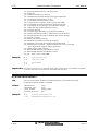
SYSTem:RESet ................................................................................................ 42
SYSTem:ERRors? ............................................................................................ 42
SYSTem:INFormation? ..................................................................................... 43
INPut Subsystem ................................................................................................... 44
INPut:FRONt [ON¦OFF]..................................................................................... 44
INPut[1-2]:LINK [OFF¦ON]................................................................................. 44
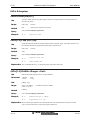
INPut[1-2]:RANGe <Range> <Unit>.................................................................. 44
INPut:SYNC [INTernal¦INTNoheader¦EXTernal¦EXTNoheader] ........................ 45
INPut:SWFilter [OFF¦CWE¦CCITT].................................................................... 45
INPut:DEEMphasis [OFF¦ON] ........................................................................... 46
6 / 71
V 3.32
>@9
Multitone Audio Test System
User Manual
INPut:TRIGger:ARMed...................................................................................... 46
INPut:TRIGger:ARMed?.................................................................................... 46
INPut:TRIGger:BREak ...................................................................................... 47
INPut:TRIGger:CONFiguration [LOOSE¦TIGHT¦USER] .................................... 47
INPut:TRIGger:USRConfiguration
<setbin1(dB)>,<setbin2(dB)>,<emptybin(dB)> .......................................... 47
INPut:TRIGger:USRConfiguration?................................................................... 48
INPut[1-2]:STATus? .......................................................................................... 48
OUTPut Subsystem ............................................................................................... 49
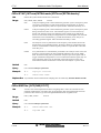
OUTPut:MTONe:PARameter <Parameter>....................................................... 49
OUTPut[1-2]:LEVel <Level> <Unit> .................................................................. 49
OUTPut:MTONe:PRETriggerlength <Length> .................................................. 50
OUTPut:MTONe:MTONelength <Length>......................................................... 50
OUTPut[1-2]:BINlevel <Level> <Unit>............................................................... 51
OUTPut[1-2]:MUTe [OFF¦ON] ........................................................................... 51
OUTPut:FLOAT [OFF¦ON] ................................................................................ 51
OUTPut:MTONe:ACTive [1¦2¦3¦4]...................................................................... 52
OUTPut:MTONe:STARt .................................................................................... 52
OUTPut:MTONe:CONtinuous ........................................................................... 52
OUTPut[1-2]:STATus? ...................................................................................... 52
OUTPut:MTONe:NAME?................................................................................... 53
OUTPut:MTONe:BLOCklength?........................................................................ 53
OUTPut:MTONe:PARameter? .......................................................................... 53
OUTPut[1-2]:MTONe:CRESt?........................................................................... 54
MEASurement Subsystem ..................................................................................... 55
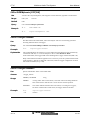
MEASurement[1-2]:LEVel:UNIT [dBVp¦Vp¦dBV¦V] ............................................ 55
MEASurement[1-2]:LEVel? ............................................................................... 55
MEASurement[1-2]:DISTortion:UNIT [dBV¦V].................................................... 55
MEASurement[1-2]:DISTortion?........................................................................ 55
MEASurement[1¦2]:MTSinad? ........................................................................... 56
MEASurement[1-2]:SELectiverss:UNIT [dBV¦V] ................................................ 56
MEASurement[1-2]:SELectiverss? <binstart> <binstop> ................................... 57
MEASurement[1-2]:NOISe:UNIT [dBV¦V] .......................................................... 57
MEASurement[1-2]:NOISe? .............................................................................. 57
MEASurement[1-2]:CROSstalk:UNIT [dB¦%]..................................................... 58
MEASurement[1-2]:CROSstalk? ....................................................................... 58
MEASurement:PHASe:UNIT [rad¦deg] .............................................................. 58
MEASurement:PHASe:SCALe <Scale> ............................................................ 58
MEASurement[1-2]:PHASe? ............................................................................. 59
MEASurement1:DTMF:STARt........................................................................... 59
MEASurement1:DTMF? .................................................................................... 59
Device Status......................................................................................................... 60
*STB?................................................................................................................ 60
*OPC................................................................................................................. 60
*OPC?............................................................................................................... 60
*CLS.................................................................................................................. 61
*ESE ................................................................................................................. 61
*ESE? ............................................................................................................... 61
*SRE ................................................................................................................. 61
*SRE? ............................................................................................................... 62
*ESR? ............................................................................................................... 62
*PSC ................................................................................................................. 62
*PSC? ............................................................................................................... 63
*IDN? ................................................................................................................ 63
*RST ................................................................................................................. 63
V 3.32
7 / 71
>@9
Multitone Audio Test System
User Manual
*TST?................................................................................................................ 63
*WAI.................................................................................................................. 64
Examples .......................................................................................................... 64
Use of an *OPC command ........................................................................... 64
Use of MAV bit in the status Byte register..................................................... 64
IEEE Standard Status Data Structure .................................................................... 65
5 APPLICATION HINTS .......................................................................... 66
Arbitrary Generator........................................................................................... 66
Alignment and Adjustments for Audio Repair Facilities .................................... 66
Cellular Phone Testing ..................................................................................... 66
Rub & Buzz Speaker Testing............................................................................ 66
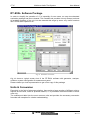
RT-EVAL Software Package ............................................................................ 67
Units & Conversion ........................................................................................... 67
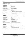
6 SPECIFICATIONS ............................................................................... 69
Generator ......................................................................................................... 69
Analyzer............................................................................................................ 69
General............................................................................................................. 69
7 INDEX .............................................................................................. 70
8 / 71
V 3.32
>@9
Multitone Audio Test System
User Manual
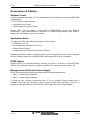
1 OVERVIEW
The trend in modern audio testing is to reduce more and more the time required for a
complete performance test of the device being tested. This tendency results partly from the
demand of broadcasters being forced to provide 24hour programming, leaving little time for
testing. In a modern studio with dozens of input channels, several routing paths and more
than 24 recording channels, a complete test including all parts of the studio becomes very
time-consuming and boring since the tests are highly repetitive.
Industrial applications also require reduced test time, especially at production lines where
any time wasting process becomes a bottleneck. Reducing test time by a factor of 20 to 50
ensures for years that testing will not be the limiting factor and increases production density.
>@9 is a modern and advanced audio test system with the capability to evaluate the
important performance Parameter of a device within a fraction of a second. >@9 is a
complete, optimized system, containing a remote controllable generator as well as an
intelligent analyzer, and can be easily integrated into an automated environment. The
system provides the highest performance and specifications to meet also the requirement of
professional equipment.
• Frequency range
20Hz to 20kHz
• Output level
-60dBVp to +20dBVp
• Input range
-60dBVp to +20dBVp
• Measurements
level, noise, distortion, crosstalk and phase in one step
• Burst transmission time typ. 250-960ms
• Residual distortion
< -86dB
>@9 is very simple in terms of connecting, handling and use within any automated
environment, but highly complex in terms of the implemented structures and algorithms to
perform the analysis in a extremely short period of time.
>@9 is very compact, using the most advanced technology available on the market. Within
its case of 19“ width and height of one unit (1.75“) only, it provides two generator channels
and two independent analyzer channels. The analyzer and generator can be operated
completely independently even though they are located in the same housing.
There is no external synchronization required to perform the analysis. Each transmitted
multitone signal contains an information header allowing any listening analyzer to
synchronize onto the signal.
Communication
Since >@9 does not provide any control elements, it must be completely controlled by a host
PC. Due to performance reasons, an IEEE-488 parallel interface has been integrated into
the instrument. This allows to transmit any command independently of the actual generator
and/or analyzer activities. The instruction to transmit a previously defined multitone signal
can be issued from the PC at any time.
Consequently, the basic requirements for the host PC is a standard IEEE-488 interface
board with installed software drivers. Detailed descriptions of the IEEE-488 connection and
all commands are filed in chapters Mains Cable and Programming respectively.
V 3.32
9 / 71
>@9
Multitone Audio Test System
User Manual
Accessories & Options
Software Tools
Following software packages for >@9 are available free of charge from your local NEUTRIK
representative.
• RT-EVAL Evaluation Software
• LabView® Driver Library
• LabWindows® CVI Driver Library
Please notice, that for either of these tools a GPIB-interface board from National
Instruments (type GPIB-PCMCIA or GPIB/TNT or GPIB-PCIIA [production year 1992 or
later]) must be installed in your host controller.
Application Notes
The appendix of this User Manual comprises the documents
• Introduction to >@9
• Get Familiar with Writing Code for >@9
• Cellular Phone Testing
• Comparison of Conventional vs. Multitone Testing
Additional application notes on speaker testing, external signal analysis etc. will be released
in future. Please contact you local NEUTRIK representative for further information.
DTMF Option
Optional PCB to be installed internally, allowing to monitor 1 channel on incoming DTMF
(Double Tone Multiple Frequency) signals in parallel to the normal operation (see p. 34).
Microphones & Phantom Power Supply
NEUTRIK provides two measuring microphones for industrial applications.
• 3382 ¼" measuring microphone
• 3384 ½" measuring microphone
To allow the use of these microphones with >@9, an optional Phantom power box is
available to provide the necessary supply voltage through XLR connectors. The box is
plugged to the input banana connectors and comes along with an AC mains adapter.
10 / 71
V 3.32
>@9
Multitone Audio Test System
User Manual
2 INSTALLATION
This chapter is intended as help for proper unpacking and installation of the >@9 system.
Please read it carefully to avoid wrong connections or inconveniences during operation of
the instrument.
Unpacking
>@9 has been carefully packed by NEUTRIK to avoid damages during transportation.
Should the box show severe damages, please immediately check the instrument inside on
external impacts. In case of any visible damage, please do not send the instrument back but
contact your local dealer and / or the carrier to avoid loss of claims for replacement.
Rack Mount
>@9 is designed to mount in a 19“ Rack and occupies one unit of height or rack space
(1.75“) only. Please allow at least 2“ additional depth at the rear side for all necessary
connectors. Make sure there is enough air circulation around the unit for cooling purposes
and please do not place >@9 besides high temperature devices such as power amplifiers in
order to avoid overheating.
The specified operating temperature ranges between 5° and 45°C (40-110F) while humidity
must not exceed 90% R.H. non-condensing.
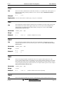
AC Power Connection
Before connecting the instrument via mains cable to the power source, make sure that the
voltage selector label on the connector / fuse holder assembly of the >@9 system matches
the supply voltage of the local area. If the instrument is not compatible with the available
power source, follow the next paragraph to change the voltage selector.
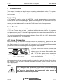
>@9 can operate from 100VAC, 120VAC and
Fig. 1 Voltage Selector
230VAC sources. To reconfigure the input line
voltage, remove the power cable and open the
flap of the connector/fuse holder at the rear
side of >@9. Either press a small screwdriver
into the slot to open the flap as shown in Fig. 1
or ruin your fingernails.
Take out the drum and insert it in the new position so that the matching voltage indication
points towards you. At the same time replace the mains fuse with the proper current rating.
For voltages of 100V to 120V a slow 2A fuse has to be installed, while for 230V a slow 1A
fuse is appropriate.
After selection of the correct mains voltage and fuse, close the flap and insert the power
cable.
>@9 is designed with a protective ground (earth) connection through
the ground wire of the power cord. This connection is essential for
safe operation. Never operate the instrument if safety ground is
unavailable or has been compromised.
V 3.32
11 / 71
>@9
Multitone Audio Test System
User Manual
Mains Cable
The enclosed mains power cable has
correspond to
Brown
Blue
Yellow/Green
an unconnected end with three colored leads, which
=
=
=
Live (AC)
Ground
Earth
Attach a mains plug to the cable that fits the receptacles of your country.
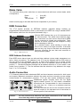
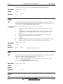
IEEE Connection
The >@9 system provides an IEEE-488 interface (standard design interface for
programmable instrumentation) which is connected to the IEEE bus using a standard IEEE488 interface cable from the rear panel illustrated in Fig. 2.
Fig. 2 IEEE Connector
With the IEEE interface bus, up to 31 instruments can
be interconnected. The cables have identical piggyback connectors on each end so that several cables
can be connected in virtually any configuration. There
must be, of course, a path from the computer to every
device operating on the bus.
As a practical matter, avoid stacking of more than
three or four cables to a single connector. If the stack
gets too long, any force on the stack can damage the
connector mounting. Be sure that each connector is
firmly screwed in place.
IEEE Address Selection
Each IEEE device has at least one talk and listen address (unless totally transparent or a
talk or listen only device). The address of the >@9 can be adjusted with the DIP switch at
the rear panel of the instrument (see Fig. 2). Each switch position has a number printed
underneath. The resulting IEEE address is the sum of all numbers, where the switch is in
position “1“. The above illustrated example has an address selection of 3, since switch 1 and
switch 2 are in position "1". The five switches allow the selection of any address in the range
from "1" to "31" inclusively.
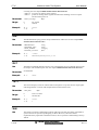
Audio Connection
>@9 features balanced and unbalanced BNC and 4mm banana connectors for both inputs
and outputs. Balanced connections enhance the noise and hum immunity and are always
recommended for measurement purposes. >@9 can also handle unbalanced signals.
Unbalanced signals normally have one hot signal
against chassis ground. For this reason unbalanced
connections are recommended for short connections
only (less than 1m / 3 feet) or in a relatively noise-free
environment.
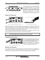
You may use either the set of front connectors with two
inputs & outputs or the equivalent set of connectors at
Fig. 3 Front Connectors
the rear panel of the instrument.
Caution:
12 / 71
Do not connect both front and rear panel connectors at the same time
since this may result in signal mismatching.
V 3.32
>@9
Multitone Audio Test System
Fig. 4 Shielded Twisted Pair Cable
User Manual
Connections between an unbalanced DUT
and the balanced inputs of >@9 should
preferably be made with shielded twisted
pair cables to avoid the introduction of
noise and hum. The shield of such a cable
shall be grounded only on one side.
Grounding the shield on both sides
increases the chance to build ground loops.
Balanced Connection
Fig. 5 Balanced BNC / Banana Connection
Fig. 6 BNC Cable - Balanced
Balanced connections with two BNC cables can be realized by connecting them to the >@9
HIGH and LOW inputs. The ground shells of both connectors are wired to ground. Do not
connect the shields together on the instrument side of the DUT but leave them open. With
balanced connections do not assemble the short circuit bar.
You may also use banana inputs instead of BNC inputs. The respective HIGH and LOW
inputs of the BNC and banana connectors are internally wired together.
Caution:
For balanced signals make sure that not only the front ground connection
is disassembled but also the ground bar at the rear panel!
Unbalanced Connection
If you use the HIGH input only of >@9
for connecting the hot output of the DUT,
use the BNC cable’s shield as the return
signal (common of the DUT output).
When using the generator in unbalanced
mode, the available level will always be
6dB (50%) below the defined level.
Fig. 7 Unbalanced Connection
Battery Low Indication
>@9 contains a battery for backup purposes of the internal memories. Life expectancy of
the battery is about ten years. Should the battery become low, the 'Error' LED will blink 3 to 4
four times after a start-up and Error 220 Battery low (memory backup) is generated.
V 3.32
13 / 71
>@9
Multitone Audio Test System
User Manual
LED Indicators
During the initialization period of >@9 system (normally <1s) all LEDs are active. If the
unit is switched ON for the very first time or after a firmware change, it has to initialize
all its signals and tables. This might take up to a few minutes, depending on the
signal resolution. All LEDs are lit during this period.
Power
This LED indicates that the power of the system is switched on,
the internal supply voltages are operating normally and the selftest of the system has been successfully completed.
Fig. 8 LED Indicators
WARNING
Should it stay off after switching on the instrument please check
whether the power cable is connected to the system, the voltage
selector is set for the correct supply voltage and the wall socket is
switched on.
Should the power LED still be off, check the power fuse in the
connector / fuse holder assembly of >@9. Please refer to AC
Power Connection to see how to open it.
Do not try to do further repairs. Call your local dealer for support.
Interface
This LED indicator lights up if the IEEE interface is busy and receives a command. It
remains illuminated until the user has read the answer from the interface. In standby mode
with no activity on the IEEE interface the LED is off.
Calculating
Whenever FFT or filtering calculations are performed this LED lights up.
Trigger
This LED indicator goes on as soon as a >@9 trigger has been successfully detected and
remains lit until the user has read the result(s) from the buffer.
Overload
Should the input signal overload one or both channels, the LED indicator goes on. This
happens if the maximum input voltage of 20dBu (10V) is exceeded or if a higher voltage than
the selected range is applied. In such a case the error LED also lights up. The overload LED
resets with the next measurement and the ranges set correctly.
Error
>@9 handles an error queue internally. Whenever an error is detected – hardware or
software – the error LED comes on. It disappears as soon as the error number has been
queried through the IEEE interface.
14 / 71
V 3.32
>@9
Multitone Audio Test System
User Manual
Test of Function
After connection of the cables and proper setting of the IEEE address it is recommended to
run the subsequent short program to confirm the proper function of the system. >@9 can be
operated with any operating system providing an IEEE-488 interface.
HT-BASIC Program Example
10
20
30
40
50
51
60
65
70
80
90
100
110
900
905
910
920
930
940
1000
1010
1020
1030
1040
1050
1060
1070
1080
1090
1100
1110
1120
1130
1140
1150
1160
1170
1180
1190
1200
1210
1220
1230
1240
V 3.32
!
RT-1M Demo Program
Adr=11
!
enter IEEE address here
Adr=Adr+700
GOSUB 900
OUTPUT Adr;"Output:Mtone:Active 1" END
OUTPUT Adr;"Output:MTone:Start" END
OUTPUT Adr;"Measurement1:Level?" END
GOSUB 1000
PRINT
GOTO 65
STOP
!
!
evaluate output/enter address J
read device informations
!
!
!
measurement loop
terminate output with END
read the measurements
!
read system information
!
interpret incoming data stream
ENTER Adr;Rcv$
Xpos=POS(Rcv$,"/")
Ypos=POS(Rcv$,",")
!
!
!
read data A
find X/Y separator
find Y/X separator
WHILE (Xpos>0) AND (Ypos>0)
X$=Rcv$[1,Xpos-1]
X=VAL(X$)
Ypos=POS(Rcv$,",")
IF Ypos>0 THEN
Y$=Rcv$[Xpos+1,Ypos-1]
ELSE
Y$=Rcv$[Xpos+1,LEN(Rcv$)]
END IF
Y=VAL(Y$)
Rcv$=Rcv$[Ypos+1,LEN(Rcv$)]
Xpos=POS(Rcv$,"/")
PRINT "Bin# ",X,"Meas: ",Y
END WHILE
RETURN
END
!
!
!
!
!
!
as long as there are separators do:
isolate X value
convert X string to value A
find Y/X separator
is there another value? >
isolate Y value
!
isolate Y value
!
!
!
convert Y string to value
delete the read XY pair from string
find next X/Y separator
DIM Inf$[100]
OUTPUT Adr;"System:Information?" END
ENTER Adr;Inf$
PRINT Inf$
RETURN
DIM Rcv$[1000]
DIM X$[10]
DIM Y$[20]
15 / 71
>@9
Multitone Audio Test System
User Manual
3 SYSTEM DESCRIPTION
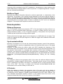
Multitone Signals
Traditionally, audio testing stimulates the device under test (DUT) with a sinusoidal signal.
This type of signal is relatively easy to handle and distortion measurements may be
performed by simply notching out the single frequency.
Amplitude [dB]
0
Amplitude
1
-10
0.8
-20
0.6
-30
0.4
0.2
-40
0
-50
-0.2
-60
-0.4
-70
-0.6
-80
-0.8
-90
-1
-100
0
10
20
30
40
50
60
70
80
90
Tme [ms]
Fig. 9 Time Plot of Sinusoidal Signal
0.5
1
1.5
2
Frequency [kHz]
Fig. 10 Spectrum of Sinusoidal Signal
More advanced tests like intermodulation distortion measurements stimulate the device with
a pair of sinusoidal signals to come closer to the real situation of audio signal transmission.
In the presence of nonlinear transfer characteristics, the DUT generates new harmonic and
intermodulation frequencies.
However, in practice the device is normally stimulated by music or speech which is a far
more complex signal than any single or twin tone test. Many frequencies with non-correlated
phase relations exist in such a real-world signal.
Therefore, multitone testing is a much more realistic approach for audio testing, emulating
the complex structure of natural sound. A multitone signal typically contains 2 to ~31 signal
frequencies, each with a certain phase relation, distributed over the frequency band of
interest. Obviously, sophisticated test instruments are necessary to analyze all these signals
with their interactions on each other.
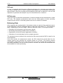
Fig. 9 and Fig. 10 show a typical multitone signal in the time- and frequency domain. It is
important to know that the waveform of the time plot strongly correlates with the phase
relations between its single frequencies. Since the max. amplitude of the time signal directly
determines the dynamic range of both the DUT and the analyzer, a low peak value is both
important and desirable.
16 / 71
V 3.32
>@9
Multitone Audio Test System
User Manual
Amplitude [dB]
0
Amplitude
1
-50
0.8
0.6
-100
0.4
-150
0.2
-200
0
-0.2
-250
-0.4
-300
-0.6
-350
-0.8
-1
-400
0
0.002
0.004
0.006
0.008
0.01
0
4
Time [ms]
Fig. 11 Time Plot of a Multitone Signal
8
12
16
20
Frequency [kHz]
Fig. 12 Spectrum of a Multitone Signal
Obviously, it is necessary to characterize the time signal by an appropriate value in order to
allow the optimization of its phase relations. The most suitable value for this purpose is the
Crest factor, which is defined as
Crest factor =
Peak _ Value
RMS _ Value
Equation 1 Crest Factor
For any (multitone) signal with given RMS value, the Crest factor will change with the peak
value, which in turn depends on the phases of the signal components. An optimal distribution
of the phases results in a low peak value of the resulting time signal and therefore a low
Crest factor (refer also to chapter Phase / Crest Factor Optimization).
NEUTRIK provides in its RT-EVAL software package a sophisticated algorithm to optimize
the phases of a multitone signal. Please contact your local representative to get a free copy
of this software.
Multitone Parameter
>@9 is a digital processing system that analyzes the transmitted signal by using Fast
Fourier Transformation (FFT) and calculates with its DSP all desired results out of the
digitized samples.
For proper use and programming of >@9 it is vital to understand the core parameter of this
analysis as well as their relationships. Consequently, the most important definitions and
formulas are explained below.
Sampling Rate
Every digitization process, i.e. conversion of an analog signal into a digital bit stream and
vice versa, has to be accomplished at a certain sampling rate (number of samples per
second). The sampling rate determines the analog bandwidth of the converter.
In >@9, the sampling rate is 48kHz, thus providing an analog bandwidth of up to 20kHz.
V 3.32
17 / 71
>@9
Multitone Audio Test System
User Manual
Blocklength
The number of samples, that are actually used for one FFT, is called blocklength. This value
determines both the duration & the frequency resolution of a multitone signal. In >@9, the
blocklength may be selected by the user in five steps from 512 to 8192.
MT Block Duration =
Blocklength
[ s]
Sampling _ Frequency
Equation 2 Duration of One Multitone Signal Block
Note
A >@9 multitone burst always comprises several multitone signal blocks,
thus resulting in a far longer duration than the ’MT Block Duration’.
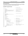
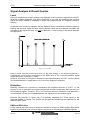
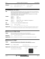
The blocklength also defines the lowest detectable frequency of the incoming spectrum. For
example, with a blocklength of 512 @ 48kHz sampling rate, a multitone block duration of
10.7ms results, corresponding to a min. frequency of ∆f = 93.75Hz (see Equation 3).
Furthermore, it is important to know that only signals with an integral number of periods
(reciprocal value of the signal frequency) fitting into one blocklength may be properly
analyzed by the FFT.
0
100
200
300
400
500
Sample Number
Fig. 13 The 5 Lowest Possible Time Periods @ Blocklength 512
In other words, only frequencies with an integral multiple of the lowest detectable frequency called frequency spacing ∆f - may be transmitted.
Frequency Spacing
The frequency spacing ∆f corresponds to the lowest frequency that can be generated &
analyzed. It defines the spectral resolution of the FFT and is calculated by following formula.
∆f =
Sampling _ frequency
48’000 Hz
=
Blocklength
Blocklength
Equation 3 Frequency Spacing
18 / 71
V 3.32
>@9
Multitone Audio Test System
User Manual
Only frequencies with an integral multiple of ∆f may be defined as signal bins (see below) of
a multitone burst.
Example
Blocklength = 512 @ 48kHz sampling rate
⇒ ∆f = 93.75Hz
⇒ available frequencies = n * 93.75Hz (n = integral number)
Bins
The frequencies, that may be transmitted in a multitone burst, are called bins. For a better
understanding, three types of bins have been introduced.
• Signal bins are those bins (frequencies) that actually build the multitone signal.
• Even bins are all the bins (frequencies) that emerge from Equation 3, i.e. the frequencies
that may be used as signal bins in a multitone signal.
• Odd bins are an effect the internal FFT computation of >@9. They represent all bins
halfway between the even bins, i.e. as if the frequency spacing would equal ∆f/2.
The subsequent relations indicate the min. and max. available frequencies (bins) in a
multitone signal at 8kHz / 48kHz sampling rate (fs).
f
min
= ∆f
{≥ 20 Hz may be generated only}
Equation 4 Minimum Signal Bin Frequency
f
max
= ∆f *
20kHz
∆f
{≤ 20kHz may be displayed }
Equation 5 Maximum Signal Bin Frequency
Besides the above equations there are no other constraints for the definition of a multitone
signal. This means you can use any bin representing a frequency below or equal to 20kHz
as a signal bin. It is up to the operator what the intention of the signal bins is. Please refer
also to chapter Signal Table.
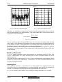
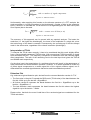
Phase / Crest Factor Optimization
In order to achieve a low Crest factor, RT-EVAL – an evaluation PC-program provided free
of charge by NEUTRIK - offers a special feature that allows to optimize the phases of any
multitone signal. The results can be loaded directly from or back into the >@9 Generator.
Low Crest factors are important for two reasons. First, the peak level of the multitone signal
raises the necessary input range for the analysis and thereby reduces sensitivity for the lowlevel signal components. Second, the low energy content of a multitone signal with high
Crest factor may barely stimulate the DUT.
A non-optimized multitone signal may show Crest factors of up to 10 (20dB), while with a
proper minimization algorithm, Crest factors as low as ~2 (6dB) can be found. This
difference of 14dB can directly enhance or decrease the dynamic range of the analyzing
system.
V 3.32
19 / 71
>@9
Multitone Audio Test System
1
0.8
1
0.8
0.6
0.6
0.4
0.4
0.2
0.2
0
0
-0.2
-0.2
-0.4
-0.4
-0.6
-0.6
-0.8
-0.8
Crestfactor=7.87
-1
0
0.005
0.01
0.015
0.02
User Manual
0.025
-1
0
0.005
0.01
Crestfactor=2.71
0.015
0.02
0.025
Fig. 15 Optimized Multitone Signal
Fig. 14 Non-Optimized Multitone Signal
Comparability of Multitone Measurements
One has to be aware that the results of multitone testing cannot be compared directly with
conventionally acquired results. For instance, distortion products may appear over the entire
band due to the fact that each signal bin produces harmonics and intermodulates with other
signal bins. The strict separation between harmonic distortion and intermodulation cannot be
guaranteed, since at certain signal bins some intermodulation products and harmonic
frequencies may fall together, thus influencing the Distortion as well as the SINAD results..
However, a multitone signal comes much closer to a "real-world“ signal than any single tone
test signal. The results are in qualitative terms comparable with conventional measurement
results as long as the specific theory behind multitone testing is considered. With a single
tone stimulus, the achieved results are directly comparable to conventional analyzers.
Please refer to the corresponding application note, filed in the appendix of this manual.
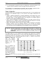
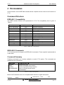
Signal Table
>@9 supports five different blocklengths. According to Equation 3 to Equation 5, each
blocklength results in the parameter of Table 1. Please observe that the minimum signal bin
frequency is ≥20Hz and that the overall duration of a burst always is longer than of a block.
Blocklength
512
1024
2048
4096
8192
Min. Burst Duration
(without Header)
154 ms
284 ms
344 ms
684 ms
854 ms
Typical Burst
Duration
260 ms
390 ms
450 ms
790 ms
960 ms
Generator
Resolution
93.8 Hz
46.9 Hz
23.4 Hz
11.7 Hz
5.9 Hz
Analyzer
Resolution
46.9 Hz
23.4 Hz
11.7 Hz
5.9 Hz
2.9 Hz
Table 1 Available Blocklengths
Blocklength 512
Frequency spacing ∆f
Analyzer resolution
Bin_Min (fmin)
Bin_Max (fmax)
93.75 Hz
46.875 Hz
1
(93.8 Hz)
213
(19.969 kHz)
Table 2 Signal Parameter with Blocklength 512 @ fs=48kHz
20 / 71
V 3.32
>@9
Multitone Audio Test System
User Manual
Blocklength 1024
Frequency spacing ∆f
Analyzer resolution
Bin_Min (fmin)
Bin_Max (fmax)
46.875 Hz
23.4375 Hz
1
(46.9 Hz)
426
(19.969 kHz)
Table 3 Signal Parameter with Blocklength 1024 @ fs=48kHz
Blocklength 2048
Frequency spacing ∆f
Analyzer resolution
Bin_Min (fmin)
Bin_Max (fmax)
23.4375 Hz
11.71875 Hz
1
(23.4 Hz)
853
(19.992 kHz)
Table 4 Signal Parameter with Blocklength 2048 @ fs=48kHz
Blocklength 4096
Frequency spacing ∆f
Analyzer resolution
Bin_Min (fmin)
Bin_Max (fmax)
11.71875 Hz
5.859375 Hz
2
(23.4 Hz)
1706 (19.992 kHz)
Table 5 Signal Parameter with Blocklength 4096 @ fs=48kHz
Blocklength 8192
Frequency spacing ∆f
Analyzer resolution
Bin_Min (fmin)
Bin_Max (fmax)
5.859375 Hz
2.9296875 Hz
4
(23.4 Hz)
3413 (19.998 kHz)
Table 6 Signal Parameter with Blocklength 8192 @ fs=48kHz
V 3.32
21 / 71
>@9
Multitone Audio Test System
User Manual
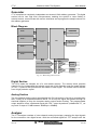
Generator
>@9 comprises a completely independent two-channel 16bit arbitrary generator. The digital
section has its own high level microprocessor enabling the system to react flexibly to
external events, communicate with various interfaces and reprogram the sample counter for
the arbitrary generator
Block Diagram
MEM 1
LED INDICATORS
MEM 2
ARBITRARY
LOGIC
CPU
IEEE-488
INTERFACE
MEM 3
MEM 4
18 BIT D/A CONVERTER
18 BIT D/A CONVERTER
ISOLATION
ISOLATION
AMP
IMPED.
MUTE
AMP
IMPED.
MUTE
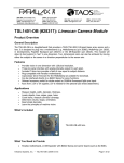
Fig. 16 Block Diagram Generator
Digital Section
The CPU reads the samples out of a non-volatile memory. The memory block provides
capacity for four independent test signals, each with 16 bit resolution and any length defined
in Table 1. Space is also provided for the header of each signal. The master clock is derived
from a high precision crystal.
Analog Section
The two-channel analog output signal behind the D/A converters is fed into a reconstruction
filter, cutting off all frequencies above 20kHz. On its way the signal also passes through an
electrical isolation to keep the complete analog output section floating. The programmable
output amplifier offers a balanced signal with 150Ω output impedance (unbalanced 75Ω) at
any level in steps of 0.1dB between -60dBVp to +20dBVp.
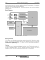
Analyzer
The >@9 analyzer consists of a two channel analog input stage, preparing the input signals
for the conversion into digital format. With the converted signals an FFT analysis with the
22 / 71
V 3.32
>@9
Multitone Audio Test System
User Manual
same blocklength as of the generated signal is performed. Further analysis of the acquired
result may be done through individual programming.
Additionally, the analyzer also provides facilities to weight an input result with different
weighting curves.
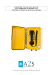
Block Diagram
AMP
A/D CONVERTER
AMP
A/D CONVERTER
CLOCK
SYNC
LED INDICATORS
IEEE-488
INTERFACE
DSP
CPU
DSP MEMORY
Fig. 17 Block Diagram Analyzer
Analog Section
>@9 features two independent analog input stages with completely independent ranging
facilities. The inputs are balanced with BNC and 4mm banana connectors at the front and
rear panel. Input impedance is 100kΩ at all inputs. Levels can be handled from 60dBVp to
+20dBVp with full dynamic range.
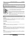
Filtering
>@9 provides a set of software weighting and Emphasis filters. The filters have a gain of 1
and can be disabled or enabled. Only one weighting filter and the Emphasis filter may be
engaged at a time. The current filters implemented are listed on the next page.
V 3.32
23 / 71
>@9
Multitone Audio Test System
Filter type
Software
C-Message
ã
ã
ã
CCITT
750µs Emphasis
User Manual
The commands INPut[1-2]:RANGe <Range> <Unit> and INPut:DEEMphasis allow to select
them.
Digital Section
The digital section consists mainly of the DSP and a logic circuitry programmed into a FPGA.
The DSP is used for all calculations - especially the FFT - and to control the range setting of
the analog input amplifiers. The DSP is connected via a bus to the central processing unit
which manages all communication to the PC and controls the system bus.
Definition of Multitone Signals
>@9 may store up to four independent two-channel multitone signals with up to 31
frequencies in a non-volatile memory. This ensures that no programming or parameter
loading is required before the generator can be operated. New signals can easily be loaded
into one of the memory blocks using an IEEE output command. For the correct syntax
please refer to OUTPut:MTONe:PARameter?.
New signals must contain following information
• >@9 memory-location to store the signal
•
•
•
•
•
•
•
•
Name of the signal
Blocklength (number of samples)
Number of signal bins for channel 1
Number of signal bins for channel 2
Signal bin numbers of channel 1
Signal bin numbers of channel 2
Phases of the signal bins for channel 1
Phases of the signal bins for channel 2
The memory location may be defined by a number from 1 to 4. Name is a user defined
ASCII string with up to 8 characters. The blocklength has to be set to one of the values
defined in Table 1. The number of signal bins defines how many frequencies shall appear in
the multitone signal for CH1 and CH2; the minimum is 1 (sinusoidal) signal, the maximum is
31 bins. The signal bin numbers have to be calculated according to Equation 7. Two blocks
of phase values for CH 1 and CH 2 terminate the definition of a multitone signal.
All signal bins have identical amplitudes. The user has the choice either to set the overall
output level of the multitone signal or, alternatively, the signal bin level. Regardless of this
choice, these values may be expressed as peak or RMS levels in linear or logarithmic units
(Vp, V, dBVp, dBV).
The overall output level of a multitone signal may be queried at any time. The same goes for
the actual Crest factor, that may be queried with the command OUTPut[1-2]:MTONe:CRESt?
24 / 71
V 3.32
>@9
Multitone Audio Test System
User Manual
or calculated by using Equation 1. With these two values, the signal bin level may be
calculated according to
Ubin RMSF =
Uout RMS
n
with n = total number of signal bins
Equation 6 Bin Amplitude
Following example shall illustrate the signal definition procedure. The multitone signal shall
have three signal bins at 300Hz, 1kHz and 3kHz. Both channels are identical. The name of
the signal is "Telefon“. Since the three frequencies are fairly wide apart, we may use a
blocklength of 512, resulting in a frequency spacing of 93.75Hz. To calculate the signal bin
numbers, refer to Equation 7
Binn = Round (
fn
f min
)=
300 Hz
=3
93.75 Hz
Equation 7 Bin Number
Consequently, the bins equaling 300Hz, 1KHz and 3KHz have the numbers 3, 11 and 32.
The definition of the phases can be done manually or by using the Crest factor optimizer of
RT-EVAL. Finally, the table may look as follows.
1,“Telefon“,512,3,3,3,11,32,3,11,32,-3.141,1.234,0.707,0,0.810,0.111
The duration of this multitone signal (not considering the header explained below) is the
reciprocal value of 93.75Hz which is 10.67ms.
ATTENTION Do never define exclusively the three signal bins @ 562.5Hz, 1406.25Hz
and 3.0kHz as multitone signal since these three frequencies form the
trigger of a multitone burst header.
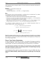
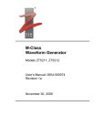
Header
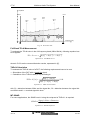
Each multitone burst is preceded by a header comprising trigger and clock synchronization.
The standard trigger signal has a
duration of 42ms and consists of 5 fixed
frequencies in the voice band with
different levels. By receiving this
frequency / level pattern a listening
analyzer recognizes a >@9 multitone
signal and wakes up. The pattern has
been selected in a way that the falsetriggering rate due to voice, music or
other synthesized signals, interpreted as
multitone signal, is < 10-6.
Clock sync.
Trigger
50
3x Multitone
100
Time [ms]
Fig. 18 Multitone Signal with 5 Bursts as Example
Additionally, a pretrigger signal may be added in order to allow the DUT to stabilize before
transmission of the rest of the multitone signal. See also command OUTPut[1-2]:LEVel
<Level> <Unit>.
During the Clock Sync period (SYNC block) with a fixed length of 64ms, the analyzer may
adjust its sampling frequency to the transmitted clock frequency (3kHz). This ensures that
V 3.32
25 / 71
>@9
Multitone Audio Test System
User Manual
frequency shifts, generated by the DUT (modulators / demodulators or tape machines with
speed differences) or slightly different clock frequencies of a separated generator / analyzer
pair are eliminated automatically.
Multitone Signal
Right after the header information follows the multitone signal itself, i.e. transmission of the
signal bins. The duration of the multitone signal depends on the block length as defined in
Table 1. The multitone signal is transmitted at least 3 times and may be repeated by applying
the command OUTPut:MTONe:MTONelength. For instance, several multitone blocks may be
transmitted before the analysis starts, in order to stabilize the DUT and to let transients
disappear. The analysis itself requires a minimum of two blocks.
Data Acquisition
Wake-up Sequence
The >@9 analyzer continuously executes a FFT of the input signal. As long as there is no
signal or any non-correlated audio information, no action is started. But as soon as the
analyzer detects a header, i.e. the >@9-specific frequency / level pattern in the input signal,
it wakes up and records the incoming multitone signal.
Please notice that the trigger signal can be detected up to -20dB below the set range. That
means for example with an input range set to -6dBu the trigger can be detected from levels
as low as -26dBu.
Synchronization Mode
Normally, the analyzer of >@9 uses the internal sample frequency clock of the generator.
This mode should be used for all applications where no frequency shifts occur on the signal
transmission path.
However, in cases where the device under test (DUT) changes the frequency of the
transmitted signal, the analyzer has to synchronize itself onto the incoming signal itself. For
this purpose, each header of a multitone burst contains a SYNC block, providing a fixed
frequency, onto which the analyzing DSP may synchronize its sampling clock. This feature
and the choice, whether a header shall be transmitted at all, may be activated with command
INPut:SYNC [INTernal¦INTNoheader¦EXTernal¦EXTNoheader], offering the four following
modes.
INTernal
The analyzer is linked to the generator clock of the same unit and the multitone signal is
preceded by a header (trigger & SYNC block). This mode may be chosen if the multitone
burst is generated in the same unit where it is analyzed and if no major frequency shifts
occur in the DUT. The burst is initiated with command OUTPut:MTONe:STARt and
transmission must not show a delay of more than 1s.
INTNoheader
Again, the analyzer is linked to the generator clock of the same unit, but no header is
transmitted. The benefit of this mode appear in noisy environments, where the trigger cannot
be detected, and for analysis of signals being generated by the DUT itself. However, the
max. allowable transmission duration is 50ms, i.e. the multitone burst must ’arrive’ at the
analyzer at latest after this time from the moment of its initiation.
26 / 71
V 3.32
>@9
Multitone Audio Test System
User Manual
EXTernal
In case of expected clock frequency differences between the generator and analyzer the
user has to activate the EXT mode. Frequency shifts appear e.g. in combination with analog
tape recorders, where the recording and the playback speed are not identical, or due to local
separation of generator and analyzer. Up to 1s transmission time is allowed.
EXTNoheader
This mode may be used after transmission of several multitone burst transmissions in mode
EXT only. The analyzer synchronizes itself onto the SYNC blocks of these preceding
multitone bursts, before it eventually gathers the burst in mode EXTnoheader.
Gathering Data
After triggering and synchronization, the analyzer waits one period of the multitone burst to
let the transients of the DUT disappear before it starts with a two-block FFT. This calculation
takes - depending on the block length - between 48ms and 190ms. The analysis includes
• Decoding of the bit stream to get two stereo signals
• Windowing with Hanning window (where necessary)
• Organization of bits (bit reverse organization of results)
• Calculation of level and phase from the complex spectrum
The calculated vector is placed in the result area of the memory and the DSP is ready for the
next acquisition.
If the user queries for measurement results, the CPU reads these stored data from the
internal memory and computes the required results out of them. This process requires
considerable computations since all the bins have to be read, squared and summed up for
the results calculation. As soon as this process is finished, the results are transmitted and
thus available for further processing.
V 3.32
27 / 71
>@9
Multitone Audio Test System
User Manual
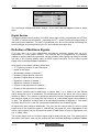
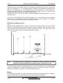
Signal Analysis & Result Queries
Level
One core requirement of audio testing is the analysis of the frequency response of the DUT.
With the multitone approach, this goal is achieved in one step by measuring the returned
signal bin levels instead of sweeping a single sine signal through the frequency band of
interest.
In practice, the frequency response can be obtained from a transmitted multitone signal by
plotting the received signal bin level values. Please notice that this analysis considers the
energies of the signal bins only, but not the distortion + noise energy in the bands between
the signal bins.
Fig. 19 Level Plot
Keep in mind, that the overall input level, i.e. the total energy of all received signal bin +
(unused) bin levels would correspond to the RMS level of the received multitone signal
(signal bin levels + distortion + noise).
However, this value is of almost no interest for the characterization of a DUT, since it reflects
its overall attenuation / amplification only, but not the frequency response.
Distortion
Basically, distortion is a measure to characterize the nonlinear behavior of a DUT, i.e. the
degree of how it generates new signal components at other frequencies than the one(s) of
the stimulating signal. Therefore, The >@9 returns as distortion results the total distortion +
noise energies (TD+N) for the bands between the signal bins of a multitone signal.
Remains the question, in which way >@9 actually calculates the TD+N values in the
frequency bands of interest. The answer can be given by considering the equations for the
RMS and RSS value.
RMS and RSS Value
Purely analog test instruments evaluate the distortion energy as RMS voltage (Root Mean
Square) by summing up all received signal components Vi according to following equation.
28 / 71
V 3.32
>@9
Multitone Audio Test System
VRMS =
∑ (V )
User Manual
2
i
with n = number of signal components
i =1..n
n
Equation 8 RMS Calculation
Unfortunately, when applying this formula on the discrete spectrum of a FFT analysis, the
result correlates in inverse proportion to the blocklength / number of bins in the respective
band. Therefore, to calculate the TD+N result out of a digitized signal, the RSS value (Root
Sum Square) has to be used.
VRSS =
∑ (V )
i
2
with i = counter over all bins ( n.. m)
i = n ..m
Equation 9 RSS Calculation
The accuracy of this approach can be proved with any spectral analyzer. The better the
resolution (i.e. the higher the blocklength), the lower is the amplitude of a single bin, since
the total energy of the band is constant. Consequently, the summing-up of the bins always
result in the same value, regardless of the chosen resolution (blocklength).
Interpretation of TD+N
To interpret the TD+N value correctly, it has to be considered that this result slightly differs
from a conventionally measured THD+N value. With conventional THD+N analysis, a single
tone stimulates the DUT. This frequency component is subtracted from the received signal
after transmission. The ratio of the remaining level to the total input level gives the THD+N
and SINAD result respectively.
On the other hand, the transmission of a multitone stimulus will result in the appearance of
many harmonics and intermodulation products. However, it is neither possible to relate any
of these signal components to a certain signal bin of the original multitone signal, nor to
differentiate the received signal between harmonics and intermodulation products.
Distortion Plot
Fig. 20 shows a typical distortion plot, derived from the returned distortion results of >@9.
• The first value in the plot D1 equals the RSS result (TD+N value) of the band between the
first bin ≥20Hz up to the last bin < SignalBin#1.
• All further results Dn represent the bands between the first bin > SignalBin#n up to the
last bin < SignalBin#n+1.
• The last distortion result represents the band between the first bin above the highest
signal bin up to the last bin ≤ 20kHz.
Please notice, that both the even & odd bins of the received signal are considered for the
TD+N calculation.
V 3.32
29 / 71
>@9
Multitone Audio Test System
User Manual
Amplitude
BinMax
Bin Min
Signal
Bin 3
Signal
Bin 2
Signal
Bin n
Signal
Bin 1
D2
D1
D..
Frequency [Hz]
Fig. 20 Distortion Plot
Full Band TD+N Measurement
To evaluate the TD+N value in the full frequency band (20Hz-20kHz), following equation has
to be applied.
TD + N FullBand =
D1 [V ]2 + D2 [V ]2 +...+ Dn [V ]2
Equation 10 Full Band TD+N
wherein D1-Dn are the returned distortion results, expressed in [V].
THD+N Calculation
To evaluate the THD+N value of a DUT, the following requirements have to be met.
• Stimulation of the DUT with a single bin signal.
• Calculation of the THD+N value (in %) according to
THD + N [%] =
D1[V ]2 + D2 [V ]2
D1 [V ]2 + L1 [V ]2 + D2 [V ]2
* 100
Equation 11 THD+N Calculation
with D1 = distortion between 20Hz and the signal bin, D2 = distortion between the signal bin
and 20kHz and L1 = received signal bin level.
MT-SINAD
For some applications, the SINAD result - being the reciprocal of THD+N - is required.
SINAD =
Signal + Noise + Distortion
Noise + Distortion
Equation 12 SINAD Definition
30 / 71
V 3.32
>@9
Multitone Audio Test System
User Manual
Obviously, to get a true SINAD result, it is necessary to stimulate the DUT with a single sine
tone only. Otherwise, i.e. if a multitone signal is applied, intermodulation products would
appear, thus increasing the Noise+Distortion value. Nevertheless, it is also possible to
calculate the SINAD result out of a transmitted multitone signal. However, in order to avoid
misunderstandings, this result is called MT-SINAD herein.
Actually, with >@9, just use the query command MEASurement[1¦2]:MTSinad?, to get the
calculated value.
In practice, the MT-SINAD result may differ slightly from a conventionally measured SINAD
value, due to intermodulation products between the signal bins. However, in qualitative
terms, the results are equal as proven in numerous setups.
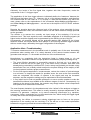
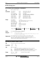
RSS Selective Measurement
The
MEASurement[1-2]:SELectiverss? <binstart> <binstop> command allows to query the TD+N
result of a user-defined band anywhere between 20Hz and 20kHz. Both the lower and the
upper border of this band may be set freely to any bin number - they don’t have to be
identical to the signal bins of the transmitted multitone signal.
Amplitude
Bin Max
Bin Min
Signal
Bin 2
Signal
Bin 3
Signal
Bin 1
Frequency [Hz]
Bin_Start
Bin_Stop
Fig. 21 RSS Selective Plot
NOTE
Be aware, that if a signal bin is within the band of interest, the RSS
selective result will represent the signal bin level + distortion + noise.
The RSS selective feature is especially helpful, if a certain component of a received signal
shall be investigated. For instance, after transmission of a single tone signal, it allows to
evaluate the individual harmonics of the fundamental frequency.
Noise
As for distortion analysis, the noise measurement divides the frequency band in subbands,
split by the signal bins, and calculates the noise values of these subbands.
V 3.32
31 / 71
>@9
Multitone Audio Test System
User Manual
Amplitude [dB]
Bin Min
Band 1
Band 2
Band 3
Band (n+1)
Band n
Bin Max
Signal 3
Bin c
Signal 2
Bin b
Signal n
Bin x
Signal 1
Bin a
Noise
Frequency [Hz]
a+1
b-1
20k
Fig. 22 Noise Plot
Consequently, a multitone measurement with n signal bins results in n+1 noise values, each
calculated internally by >@9 according to the following formula.
Noisei = 2 *
b −1
∑ (U )
i = a +1
2 i −1
2
= RSS value of all odd bins in a band
Equation 13 Noise Calculation
NOTE
Equation 13 describes the internal noise calculation of >@9, i.e. the actually
returned noise results must not be re-calculated in any way.
Full Band Noise
MeasurementTo evaluate the noise value in the full frequency band (20Hz-20kHz), following
equation has to be applied.
N FullBand =
N 1 [V ]2 + N 2 [V ]2 +...+ N n [V ]2
Equation 14 Full Band Noise
wherein N1-Nn are the returned noise results, expressed in [V], of any multitone
measurement.
32 / 71
V 3.32
>@9
Multitone Audio Test System
User Manual
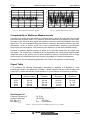
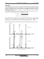
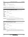
Crosstalk
The Crosstalk Plot may be calculated only if a stereo signal is transmitted. This stereo signal
must have separate bins set in the 2 channels in a way that the respective bins remain
unused in each other channel. In case of bad channel separation of the DUT, the unique
frequencies of channel "A" talk into channel "B", i.e. they appear in the received signal of
channel "B" and vice versa.
The crosstalk value is the ratio of the unused bin level in channel "B" and the active bin level
of channel "A" at the same frequency. It is expressed in % or dB.
Crosstalk iLEFT =
Unused _ Bin _ ChBi
Set _ Bin _ ChAi
Equation 15 Calculation of Crosstalk
As an example, we may assume that a signal bin with 10dB @ 1kHz is transmitted via
channel "A", while at channel "B" the received bin level @ 1kHz equals -30dB.
Consequently, the crosstalk from channel "A" to channel "B" @ 1kHz is 1% or -40dB.
Please note that noise increases the crosstalk value and thereby falsifies the measurement.
Amplitude
Transmitted
Signal
Bin 1a
Transmitted
Signal
Bin Xa
Transmitted
Signal
Bin 2a
&KDQQHO$
Received
Signal
Bin 2b
Received
Signal
Bin 1b
Frequency [Hz]
20
Amplitude
20k
Transmitted
Signal
Bin 2b
Transmitted
Signal
Bin 1b
&KDQQHO%
Received
Signal
Bin 1a
Received
Signal
Bin 2a
Received
Signal
Bin Xa
Frequency [Hz]
20
20k
Fig. 23 Crosstalk Plot
V 3.32
33 / 71
>@9
Multitone Audio Test System
User Manual
Phase
Since the analyzer knows all information about the transmitted multitone signal from the
generator, also the phases of the signal bins are available for further analysis. Therefore, the
analyzer may calculate any changes of inter-channel phase relations at each common signal
bin of the 2-channel test signal.
ϕ i = ϕ (U iLeft ) − ϕ (U iRight )
Equation 16 Phase Calculation
However, the exact phase shift between generator output and analyzer input cannot be
calculated due to the unknown time delay of the DUT.
DTMF Mode
The DTMF option extends the measuring capabilities of >@9 in the field of phone testing. It
allows to receive & analyze the standardized DTMF (Double Tone Multiple Frequency) tones
on channel 1.
Every key of a standard 4x4 phone keypad is represented by a dual tone. These tones
comprise the indicated frequencies as shown in Table 7.
1209Hz
1336Hz
1477Hz
1633Hz
697Hz
1
2
3
a
770Hz
4
5
6
b
852Hz
7
8
9
c
941Hz
*
0
#
d
Table 7 DTMF Signal Coding
For instance, the DTMF tone for key #6 is put together of the two frequencies 770Hz &
1477Hz.
The meaning of the four ’empty’ keys a-d in the last row may be user-defined.
The DTMF mode of >@9 may be started and reset by using command
MEASurement1:DTMF:STARt. From then on, the unit continuously monitors the input
channel 1 in parallel to any other operation, and stores all received DTMF tones in an
internal buffer.
This 32 keys wide buffer may be queried by command MEASurement1:DTMF?. To clear the
contents of the buffer, command MEASurement1:DTMF:STARt has to be sent to the unit.
The input range of channel 1 must be adjusted to the level of the DTMF tones to be
analyzed. Please notice that an overload, caused by an incoming DTMF signal, will not be
detected, i.e. the unit will not generate an error message. Furthermore, no DTMF tone
analysis will be possible in such a case.
34 / 71
V 3.32
>@9
Multitone Audio Test System
User Manual
Broadcast Mode
The broadcast mode allows to let the analyzer of a >@9 unit wait for an incoming multitone
burst that has been generated by another, remote >@9 unit (generator & analyzer are
physically apart). By this, it becomes possible to measure e.g. the characteristics of a
transmission line.
Following restrictions have to be considered on behalf of the broadcast mode.
• The measurements under the broadcast mode can be done in one direction only at a
time. In order to return a multitone burst in the opposite direction, i.e. from the previously
used analyzer to the generator, the operation mode of both units has to be changed.
• The generator & analyzer must be controlled each by a PC through a GPIB interface.
• The transmitted multitone signal must be defined identically on the generator & analyzer.
• In order to avoid false triggering, it is vital to thoroughly understand and apply the trigger
configuration as well as the setting of a proper output level and input range in the
generator and analyzer.
Mode of Operation
The broadcast mode of >@9 is based on the command INPut:TRIGger:ARMed. If sent to the
unit, this instruction sets the analyzer to a state where it waits until it detects an incoming >@
9 trigger and receives the connected multitone signal.
The trigger must have been generated by another >@9 instrument and has to match the
trigger conditions defined in the analyzing unit.
Setup
The complete procedure to set up a broadcast transmission test with >@9 may be
summarized as follows.
1. Install the generator and analyzer at the intended locations and control each of them
with an own PC through GPIB IEEE interfaces.
2. Connect the two units with the ends of the transmission line to be measured.
3. Write an appropriate program to control the units. Optionally, you may also install RTEVAL V1.60 or higher on both host PCs.
4. Define a multitone signal according to the specific demands of the test (available
bandwidth, number of bins, signal duration etc.) identically on both the generator and
analyzer. Don’t forget to optimize the Crest factor of the signal (e.g. by using the Crest
optimizer of RT-EVAL).
5. In the analyzer, set the trigger configuration to TIGHT by using command
INPut:TRIGger:CONFiguration [LOOSE¦TIGHT¦USER].
6. Set the SYNC mode of the generator to INTernal with command INPut:SYNC INTernal.
7. Set the output level of the generator approximately to the level of the broadcast signal.
Make sure that no clipping occurs.
8. Set the SYNC mode of the analyzer to EXTernal with command INPut:SYNC EXTernal.
9. Adjust the input range of the analyzer to the incoming signal level. To do this, connect
the analyzer to the transmitted broadcast signal and reduce the input range until the
Overload LED lights up. Increase the input range by +6dB from this value in order to
provide enough headroom.
10. Set the analyzer to the armed mode with command INPut:TRIGger:ARMed.
11. Interrupt the broadcast signal and transmit the multitone burst with command
OUTPut:MTONe:STARt.
V 3.32
35 / 71
>@9
Multitone Audio Test System
User Manual
12. It is recommended to transmit the burst at a defined time, so that the operator of the
analyzer realizes immediately, whether the trigger has been detected or not.
If no successfull line measurements are possible, read the chapter Application Hints /
Troubleshooting (p. 37) to check possible causes and work out solutions.
Trigger Configuration
The most important topic of broadcast mode measurements with >@9 is the definition and
application of an appropriate trigger. For this purpose, three trigger configurations are
provided.
• LOOSE - standard configuration for industrial applications (noisy signals with a poor
dynamic range, or internal link between generator & analyzer). The trigger condition is
met rather easily, i.e. false triggerings have to be expected if the multitone signal is
introduced into an ordinary broadcast program etc.
• TIGHT - special configuration for broadcast applications. The trigger condition has been
tightened by far vs. LOOSE in order to avoid false triggerings. Requires an accurate
setting of the generator output level and analyzer input range.
• USER - this parameter allows to define the trigger condition according to user-specific
demands. However, since this application requires a very thorough and detailed
understanding of the whole triggering complex, this approach is for very advanced users
only, who have a profound understanding of all possibilities and their consequences.
ATTENTION Improper configuration of the USER trigger may result in a ’always’ or
’never’ condition, where the analyzer triggers on almost every incoming
signal (music, speech etc.) or never recognizes any trigger, even if it is a
correct one.
The trigger signal of a >@9 multitone burst comprises three signal bins at different
frequencies and with individual levels. In order to avoid false triggerings, the receiving >@9
permanently monitors the input signal on strictly this pattern. Furthermore, the analyzer
checks whether two more, predefined signal bins are ’empty’, i.e. whether no level can be
detected at these two Amplitude [dB]
frequencies. If this is the
case,
the
analyzer
recognizes the incoming
0dB
signal
as
a
>@9
b
multitone
burst
and
triggers to it.
a
a
c
c
Fig. 24 visualizes the
characteristic of a >@9
triggersignal. The bottom
bars ( T ) at the frequencies 1, 3 and 5 represent the set signal bins
Frequency
1
2
3
4
5
and their amplitudes, defined against the ground
Fig. 24 Trigger Definition
level of the generator,
whereby signal bin 1 and 5 have identical amplitudes. The frequencies 2 & 4 represent the
empty bins.
36 / 71
V 3.32
>@9
Multitone Audio Test System
User Manual
Obviously, the levels of the five signal bins, together with their frequencies, make the
uniqueness of the >@9 trigger signal.
The application of the User trigger allows to individually define the ’headroom’ between the
0dB line and the bottom bars ( T ). However, this is a very delicate operation, and therefore
not recommended for new users of >@9. Anyway, in case that this feature truly has to be
used, please refer to the explanations of the commands INPut:TRIGger:CONFiguration ...
and INPut:TRIGger:USRConfiguration ... as well as to the helpfile of the RT-EVAL software
package.
Remains the question about the reference level of the analyzer, since especially for longdistance transmission lines, this instrument cannot use the same reference voltage potential
as the generator.
The solution is to assume the currently set input range of the analyzing >@9 unit as
reference level. This level equals the max. detectable amplitude of all incoming signals (all
higher levels would be clipped), and is represented by the 0dB line on top of Fig. 24.
Consequently, all received signals will be analyzed against 0dB. Applied on the trigger
detection criteria, this means that the level pattern of an incoming multitone trigger must be
within a certain range, defined by the trigger configuration of the analyzer.
Application Hints / Troubleshooting
To execute measurements in the broadcast mode is probably one of the more demanding
procedures when working with >@9, mainly because of the remote location between the
generator and analyzer, i.e. the sender and receiver of the multitone burst.
Nevertheless, by considering both the instructions listed in chapter Setup (p. 35) and
following hints, it shouldn’t become a major problem to establish a properly working set up.
• The most effective approach to successfully execute a first test run, is to place the
sender & receiver not too far apart (e.g. in the same room), however, with both units
already being controlled by individual PCs. Such a setup may probably not include a long
transmission line, but is ideally suited to adjust the required settings of the majority of the
involved systems to allow a proper measurement.
• For the first signal transmissions / measurements, reduce the number of involved stages
to a minimum, to simplify the search for possible errors. As soon as the first successful
tests are completed, the number of systems in the signal path may be increased
stepwise, and the respective settings may be optimized to the actual demands.
• A very helpful tool to find out possible problems is to use a monitor speaker to make the
transmitted multitone burst audible at the different stages of the line. Consequently, by
listening to the sound of the burst, the operator may simply localize critical components
and optimize their transmission behaviour.
The most frequent obstacle in the broadcast mode is the ’refusal’ of the analyzer to trigger to
the incoming multitone burst. This effect is usually caused by improper adjustments of the
involved >@9 generator / analyzer, or by sound enhancing instruments (e.g. equalizer,
compressor, limiter, compander etc.) on the transmission line, which modify the trigger signal
in a way, that it can’t be recognized anymore.
Consequently, the efforts to overcome missing triggerings have to focus on the proper
adjustment of the sending and the receiving >@9, as well as on the mutual optimization
between the trigger signal and the sound enhancing systems.
Possible Cause
V 3.32
Effect
Suggested Solution
37 / 71
>@9
Generator output level too low
and/or
Analyzer input range too high
Multitone Audio Test System
The incoming trigger signal level
doesn’t match vs. the analyzer
sensitivity, so that the trigger can’t
be recognized
Generator output level too high The trigger signal is modified by
sound enhancing units in a way,
that it can’t be recognized any
more by the analyzer
User Manual
Increase the generator output
level or decrease the analyzer input range stepwise
Reduce or attenuate generator output level
Analyzer input range too low
The input stage of the analyzer is too Increase input range of anasensitive, i.e. overloaded, and
lyzer stepwise
therefore can’t recognize the incoming trigger
Very strong sound enhancing
effects or a low quality of
the transmission line
Distortions, noise or sound enhancing effects modify the trigger signal in a way, that it can’t be recognized any more by the analyzer
Switch Off all sound enhancing systems during the
transmission of the multitone burst
Multitone signal not identical
on generator & analyzer
Analyzer triggers correctly, but can’t
acquire a reasonable result
Set the identical signal bins in
the active multitone signal
of the generator & analyzer
Table 8 Broadcast Mode Troubleshooting
38 / 71
V 3.32
>@9
Multitone Audio Test System
User Manual
4 PROGRAMMING
Communication via the IEEE-488 interface allows complete remote control for all functions of
>@9.
Command Structure
IEEE-488.1 Compatibility
The IEEE interface function set implemented in >@9. The compatibility level is given in
Table 9.
Function
Implemented
Source handshake
Acceptor handshake
Talker
Talker (extended)
Listener
Listener (extended)
Service request
Remote local
Parallel poll
Device clear
Device trigger
Controller
SH1
AH1
T6
TE0
L4
LE0
SR1
RL0
PP0
DC1
DT0
C0
Notes
Complete capability
Complete capability
No talk-only mode
No capability
No listen-only mode
No capability
Complete capability
Only local lockout
No capability
Complete capability
No capability
No capability
Table 9 IEEE 488.1 Compatibility
IEEE-488.2 Commands
>@9 currently does not support all IEEE-488.2 commands. These might be implemented at
a later state.
Command Summary
Following commands are currently available to control >@9 system. The commands are
divided into four subsystems.
Subsystem
SYSTEM
INPUT
OUTPUT
MEASUREMENT
*
Function in RT-1M
Control of RT-1M
Control of analyzer input section
Control of generator output section
Query for measurement results
Device Status
Table 10 Subsystem Definition
Most of the Parameter have to be completed with channel or signal information.
SYSTem:
V 3.32
RESet
MEASurement:
LEVel:
UNIT
39 / 71
>@9
Multitone Audio Test System
SYSTem:
SYSTem:
ERRors?
INFormation?
INPut:
INPut:
INPut:
INPut:
INPut:
INPut:
INPut:
INPut:
INPut:
INPut:
INPut:
INPut:
INPut:
FRONt
LINK
RANGe
SYNC
SWFilter
DEEMphasis
TRIGger:
TRIGger:
TRIGger:
TRIGger:
TRIGger:
TRIGger:
STATus?
OUTPut:
OUTPut:
OUTPut:
OUTPut:
OUTPut:
OUTPut:
OUTPut:
OUTPut:
OUTPut:
OUTPut:
OUTPut:
OUTPut:
OUTPut:
OUTPut:
OUTPut:
MTONe:
MTONe:
LEVel
BINlevel
MTONe:
MTONe:
FLOAT
MUTe
MTONe:
MTONe:
MTONe:
MTONe:
MTONe:
MTONe:
STATus?
ARMed
ARMed?
BREak
CONFiguration
USRConfiguration
USRConfiguration?
PARameter
ACTive
PRETriggerlength
MTONelength
STARt
CONTinuous
PARameter?
NAME?
BLOCklength?
CRESt?
MEASurement:
MEASurement:
MEASurement:
MEASurement:
MEASurement:
MEASurement:
MEASurement:
MEASurement:
MEASurement:
MEASurement:
MEASurement:
MEASurement:
MEASurement:
MEASurement:
MEASurement:
User Manual
LEVel?
DISTortion:
DISTortion?
MTSinad?
SELectiverss:
SELectiverss?
NOISe:
NOISe?
PHASe:
PHASe:
PHASe?
CROSstalk:
CROSstalk?
DTMF:
DTMF?
UNIT
UNIT
UNIT
UNIT
SCALe
UNIT
STARt
*STB?
*OPC
*OPC?
*CLS
*ESE
*ESE?
*SRE
*SRE?
*ESR?
*PSC
*PSC?
*IDN?
*RST
*TST?
*WAI
Descriptive Symbols
Following terms are used in the command description.
Symbol
Description
[ ]
Used to enclose one or more optional Parameter to control RT-1M. Omitting
the default Parameter causes the system to use the default action.
{ }
Used to enclose one or more Parameter that may be included several times.
?
Indicates a query by appending the question mark to the last keyword in a
command. Not all commands have a query; some are only query commands.
¦
Read this signal as an “OR“. It is used to separate alternative Parameter.
< >
Used to enclose an SCPI defined parameter
:
Used to separate elements of a RT-1M command
;
Used to separate commands in a command list
,
Used to separate arguments in an arguments list
( )
Used to indicate a range of suffixes available
:→
String is sent from the controller to RT-1M
→:
Returned string from RT-1M to the controller
Table 11 Symbol Description
>@9 accepts only the short or the exact and full form of the statements. Sending a
command that is neither will generate an error. In following command list, the CAPITAL
40 / 71
V 3.32
>@9
Multitone Audio Test System
User Manual
letters indicate the short form to help reduce the required typing. However, the >@9 parser
accepts both lowercase and UPPERCASE commands, i.e. it is not case sensitive.
Command Notation
In the listing of >@9 commands, descriptive headings are used to divide the information into
easily readable parts. The used headings and the contents are shown below. If a heading
does not apply on a command, it is not listed.
Use
What the command does and additional information is given in the heading.
Answer
Lists the possible answers on a query and their types (integer, float, boolean, string).
Parameter
Description of the Parameter to be set and their types (integer, float, boolean, string).
Range
List of the available Parameter and their types (integer, float, boolean, string).
Default
Description of the default parameter. After a RESET, all Parameter in an instrument are set to
their default values.
Unit
Specification of the available parameter units.
Resolution
Definition the step size of a <Numeric_Value>
Query
Indicates the query command, corresponding to the described command.
Example
Command examples are provided here. The short form and lowercase characters are used as a
reminder that both forms are allowed.
Explanation Additional explanations and hints.
V 3.32
41 / 71
>@9
Multitone Audio Test System
User Manual
Command Set
SYSTem Subsystem
SYSTem:RESet
Use
Initiates a software RESET. All set Parameter in the instrument are re-set to their default
values. Error queue is cleared.
Example
:→
SYST:RES
:→
System:reset
Explanation The RESET command initializes the complete instrument including the IEEE interface.
Commands, that are in the command buffer, or those which are entered shortly after the
RESET, may be deleted by the RESET command and are therefore not executed.
SYSTem:ERRors?
Use
Queries the number and types of errors since the last Query ¦ Startup ¦ System:Reset
command.
Answer
<Error_No>
Range
100
101
102
110
120
121
130
131
132
133
140
141
145
149
150
151
152
153
154
155
156
157
158
159
160
161
162
163
164
165
166
167
168
42 / 71
integer
No subsystem separator found (':')
No subsystem found
No command separator found (':')
No SYSTem command found (e.g. RESET)
No INPut command found (e.g. LINK)
No INPut[1-2] command found (e.g. RANGE)
No OUTPut command found (e.g. FLOAT)
No OUTPut[1-2] command found (e.g. LEVEL)
No MTONe command found (e.g. START)
No TRIGger command found (e.g. ARMed)
No MEASurement command found (e.g. LEVEL)
No MEASurement[1-2] command found (e.g. TDN)
No device status command found (e.g. *OPC)
TRIGger configuration parameter expected (e.g. LOOSE)
No parameter expected
Float parameter expected
Float parameter out of range (e.g. INP:RANG -5E3)
Integer parameter expected
Integer parameter out of range
String parameter expected (e.g. "ON")
"ON" or "OFF" string expected
Filter parameter expected (e.g. "CCITT")
Location parameter expected (e.g. "FRONT")
Sync parameter expected (e.g. "EXTERNAL")
String too long
Wrong number of samples (512,1024,2048,4096,8192)
Corresponding frequency to bin number out of range
Phase value out of range
Wrong number of MT Parameter
IEEE bus error
Output buffer overflow
Bins must be in increasing order
Too many parameter
V 3.32
>@9
Multitone Audio Test System
User Manual
169
170
180
182
190
191
199
200
201
202
203
204
205
206
210
220
230
240
246
Integer parameter must be in increasing order
Illegal unit
Option not installed (e.g. FLOAT)
Command not executable during input trigger armed mode
Not available in this hardware version
Not available with this firmware version
Unexpected error occurred – please report to NEUTRIK
No parameter in list for start multitone signal in generator
No parameter in list referring to received data in analyzer
Output 1&2 muted while multitone is started
No trigger detected
No stereo trigger detected (e.g. for phase measurement)
Measurement function needs ≥1 identical bins on both channels
Measurement function needs ≥1 different bins on both channels
Analyzer overload
Battery low (memory backup)
Hardware and software revisions do not match
Minimum one external measurement required beforehand
Measurement not possible – Signal bins defined too close to each other
(chose higher block length or change signal bins)
250 DTMF receive buffer overflow
255 RS232/GPIB Interface Output Buffer overflow
256 RS232/GPIB Interface Input Buffer overflow
600-716 Please report to NEUTRIK
Example
:→
→:
System:Errors?
130,203,204
:→
→:
SYST:ERR?
0
Explanation If no errors occurred, a "0" is returned. In any other case the list of error numbers in the queue
is returned. All errors are cleared in the instrument after the query.
SYSTem:INFormation?
Use
Query for serial number, hardware revision and firmware version of RT-1M system.
Compatible with SCPI <*IDN?> command.
Answer
<Manufacturer>
<Instrument_type>
<Serial_number>
<Firmware_Revision>
Example
:→
→:
V 3.32
string
string
string (4 digits)
float
System:Information?
NEUTRIK,RT1M,0456,3.20
43 / 71
>@9
Multitone Audio Test System
User Manual
INPut Subsystem
INPut:FRONt [ON¦OFF]
Use
Activates either front or rear panel input connectors (output connectors are always active at
front & rear panel).
Range
OFF ¦ ON
boolean
Default
ON
(front input connectors are active)
Query
Use command INPut[1-2]:STATus?
Example
:→
Inp:Fron OFF
INPut[1-2]:LINK [OFF¦ON]
Use
Links internally the generator output of RT-1M to the analyzer input. The input connectors of
the selected channel are physically disconnected at front and rear.
Range
OFF ¦ ON
Default
OFF
Query
Use command INPut[1-2]:STATus?
Example
:→
Input2:Link ON
:→
INP1:LINK OFF
boolean
Explanation This command allows e.g. to check the proper operation of RT-1M.
INPut[1-2]:RANGe <Range> <Unit>
Use
Defines the input range & unit for an input channel.
Parameter
<Range>
<Unit>
Unit
[dBVp ¦ Vp]
Range
-60 to +20 dBVp
0.001 to 10 Vp
Default
0 dBVp
Query
Use command INPut[1-2]:STATus?
Example
:→
INPUT1:Range 0 dBVp
:→
Inp2:Rang 0.5 Vp
float
string
(rounded to nearest 0.1dBV)
Explanation Insert a white space between the value and the unit. The allowed units are peak level units
only, since the Crest factor of the input signal is unknown.
44 / 71
V 3.32
>@9
Multitone Audio Test System
User Manual
INPut:SYNC [INTernal¦INTNoheader¦EXTernal¦EXTNoheader]
Use
Defines the synchronization mode of the instrument.
Range
INT ¦ INTN ¦ EXT ¦ EXTN
boolean
INT
Analyzer sampling clock is derived from the generator crystal. No frequency shift
correction is performed. Use this mode if analyzer and generator are located
together and no frequency shifts are expected. Max. allowable time delay is 1s.
INTN
Analyzer sampling clock is derived from the generator crystal. No frequency shift
during transmission must occur. The multitone signal is sent out without any
header. The analyzer expects the multitone signal without trigger and SYNC
block. Use this mode if analyzer and generator are located together but no header
information can be transmitted (e.g. muted measurements) or for analysis of
externally generated signals. Max. allowable time delay is 50ms.
EXT
The analyzer clock is synchronized to the frequency of the SYNC block in the
header of the received multitone burst. Frequency shifts are compensated. This
mode is recommended if notable frequency shifts are expected. Max. allowable
time delay is 1s.
EXTN
No synchronization is transmitted or performed at all. Analyzer clock runs at the
frequency synchronized to the last transmitted multitone burst in Sync Mode
EXT. No further tuning will be performed. Analyzer expects the signal with no
trigger information and generator is set to transmit the multitone signal only. No
major time delay must occur in that mode. This mode requires at least one
measurement in EXT mode before to ensure that the analyzer crystal is tuned.
Default
INT
Query
Use command INPut[1-2]:STATus?
Example
:→
Inp:Sync Internal
:→
INPUT:SYNC INTN
Explanation Any multitone burst transmission & sampling must be initiated by OUTPut:MTONe:STARt.
INPut:SWFilter [OFF¦CWE¦CCITT]
Use
Activates one of the implemented software weighting filters. Filters are selected for both
channels simultaneously. The filters may be engaged also after the measurements has been
performed. This allows to get first unweighted and afterwards weighted results.
Range
OFF ¦ CWE ¦ CCITT
Default
OFF
Query
Use command INPut[1-2]:STATus?
Example
:→
INPUT:SWFILTER OFF
:→
Inp:SWF CWE
V 3.32
boolean
45 / 71
>@9
Multitone Audio Test System
User Manual
INPut:DEEMphasis [OFF¦ON]
Use
Activates the 750µs deemphasis, which applies on both channels, regardless of other filters.
Range
OFF ¦ ON
Default
OFF
Query
Use command INPut[1-2]:STATus?
Example
:→
INP:DEEM ON
:→
Input:Deemphasis OFF
boolean
INPut:TRIGger:ARMed
Use
Puts RT-1M into the armed mode, where the analyzer waits for an externally generated
incoming multitone burst with trigger.
Query
Use commands INPut:TRIGger:ARMed? and INPut[1-2]:STATus?
Example
:→
Explanation
This command allows the analyzer to receive multitone bursts that have been generated by
a remote RT-1M unit, i.e. to run the analyzer in the so-called Broadcast Mode.
In the armed status, the Trigger LED will be flashing until a trigger is detected (LED is lit).
Inp:Trigger:Armed
Keep in mind that for broadcast applications it is necessary to set the synchronization mode
of the generator / analyzer to INTernal / EXTernal, while the trigger configuration for both
units must be TIGHT (see p. 3-36).
INPut:TRIGger:ARMed?
Use
Queries whether RT-1M is in the armed mode.
Answer
<Trigger_Status>
Range
ARMED ¦ STOPPED
Example
46 / 71
string
ARMED
As long as RT-1M is in this mode, it will wait until an incoming multitone
burst is detected or until the unit is re-set into the normal operation.
STOPPED
This status indicates that RT-1M is not armed (i.e. waiting for a trigger),
but in the normal mode. In this status, the Trigger LED will be dark.
:→
→:
Inp:Trigger:Armed?
ARMED
V 3.32
>@9
Multitone Audio Test System
User Manual
INPut:TRIGger:BREak
Use
Disables the armed mode of RT-1M, i.e. re-sets the unit into the normal mode.
Query
Use commands INPut:TRIGger:ARMed? and INPut[1-2]:STATus?
Example
:→
Explanation
This command returns RT-1M into the normal operation, after it has been in the armed
mode.
In the normal mode, the Trigger LED will be dark.
Inp:Trigger:Break
INPut:TRIGger:CONFiguration [LOOSE¦TIGHT¦USER]
Use
Sets the trigger configuration.
Range
LOOSE ¦ TIGHT ¦ USER
string
LOOSE
Applies the normal trigger condition on an incoming multitone burst. This
configuration is especially suited for industrial applications, where both
multitone generator and analyzer are located in the same housing.
TIGHT
Applies the tight trigger condition on an incoming multitone burst. This
configuration should be used for broadcast applications, where the signal is
inserted into a shortly interrupted broadcast signal.
USER
This configuration allows the user to define the trigger condition
individually. However, since this requires a highly sophisticated finetuning, it is strongly recommended to be used by very advanced users only.
Default
LOOSE
Query
Use command INPut[1-2]:STATus?
Example
:→
Explanation
It is recommended to change the trigger configuration for broadcast operation only, and to
select the TIGHT condition in such cases. As soon as RT-1M is used again for industrial
applications, the trigger configuration should be re-set to LOOSE.
Inp:Trigger:Configuration Tight
INPut:TRIGger:USRConfiguration
<setbin1(dB)>,<setbin2(dB)>,<emptybin(dB)>
Use
Allows to custom-design the trigger configuration by defining the trigger bins.
Parameter
<setbin(1)>
<setbin(2)>
<emptybin>
integer
integer
integer
Range
<setbin(1)>
<setbin(2)>
<emptybin>
-10 to -50 dB
-10 to -50 dB
0 to -80 dB
Query
Use command INPut:TRIGger:USRConfiguration?
Example
:→
V 3.32
Inp:Trigger:Usrconfiguration -20,-40,-80
47 / 71
>@9
Multitone Audio Test System
Explanation
User Manual
This command requires highly sophisticated handling for proper operation!
It shall not be applied as by very advanced users only!
INPut:TRIGger:USRConfiguration?
Use
Queries the defined trigger configuration.
Answer
<setbin1>
<setbin2>
<emptybin>
integer
integer
integer
Range
<setbin1>
<setbin2>
<emptybin>
-10 to -50 dB
-10 to -50 dB
0 to -80 dB
Example
:→
→:
Explanation
See chapter Broadcast Mode.
Inp:Trigger:Usrconfiguration?
-20,-40,-80
INPut[1-2]:STATus?
Use
Queries the complete input channel status.
Answer
<Range_Unit>
<SW_Filter>
<Front_Conn>
<Link>
<SYNC_Mode>
<Deemphasis>
<Trig_Config>
Example
:→
→:
Inp2:Status?
RANGE -3.5000E0 dBVp,SWFILTER CCITT,FRONT OFF,
LINK ON,SYNC INTERNAL,DEEMPHASIS ON,TRIGGER:
CONFIGURATION LOOSE
:→
→:
INPUT1:STAT?
RANGE 1.0000E1 Vp,SWFILTER OFF,FRONT ON,LINK
OFF,SYNC EXTERNAL,DEEMPHASIS ON,TRIGGER:
CONFIGURATION TIGHT
48 / 71
float & string
boolean
boolean
boolean
boolean
boolean
string
RANGE [-60 to +20 dBVp ¦ 0.001 to 10 Vp]
SWFILTER [OFF ¦ CWEighting ¦ CCIT]
FRONT [OFF ¦ ON]
LINK [OFF ¦ ON]
SYNC [INT ¦ INTN ¦ EXT ¦ EXTN]
DEEMPHASIS [OFF ¦ ON]
TRIGGER [LOOSE ¦ TIGHT ¦ USER]
V 3.32
>@9
Multitone Audio Test System
User Manual
OUTPut Subsystem
OUTPut:MTONe:PARameter <Parameter>
Use
Defines a multitone signal.
Parameter
<Sig_Number>
<Sig_Name>
<No_Of_Samples>
<No_Of_Bins_CH1>
<No_Of_Bins_CH2>
{<Bin_X_CH1>}
{<Bin_X_CH2>}
{<Phase_X_CH1>}
{<Phase_X_CH2>}
integer
string
integer
integer
integer
integer
integer
float
float
Range
<Sig_Number>
<Sig_Number>
<No_Of_Samples>
<No_Of_Bins_CH1>
<No_Of_Bins_CH2>
<Bin_No_X_CH1>
<Bin_No_X_CH2>
<Phase_X_CH1>
<Phase_X_CH2>
1¦2¦3¦4
(up to 8 ASCII characters, no spaces allowed)
512 ¦ 1024 ¦ 2048 ¦ 4096 ¦ 8192
1 to 31
1 to 31
Bin_Min1) to Bin_Max2)
Bin_Min1) to Bin_Max2)
-π to +π
-π to +π
1)
Bin _ Min =
target memory of RT-1M
user-defined signal name
blocklength
total number of bins set in channel 1
total number of bins set in channel 2
bin numbers set in Chn1
bin numbers set in Chn2
phases of bins set in Chn 1
phases of bins set in Chn 2
NoOfSamples
* 20 Hz
48’000 Hz
Query
Use command OUTPut:MTONe:PARameter?
Example
:→
2)
Bin _ Max =
NoOfSamples
* 20 kHz
48’000 Hz
Output:Mtone:Par
1,’Telefon’,2048,3,3,25,85,256,25,85,256,0,1.5707
,3.14,0,1.5707,3.1415
Explanation This command defines all compulsory parameter of a new multitone signal.
<No_Of_Bins_CHX> equals the total number of signal bins for channel 1 / 2.
<Bin_No_X_CHY> indicate the bin numbers as calculated with Equation 7 (p. 25).
<Phase_X_CHY> indicate the phases of the signal bins.
OUTPut[1-2]:LEVel <Level> <Unit>
Use
Set the total output level of the multitone signal.
Parameter
<Level>
<Unit>
Unit
dBVp ¦ Vp ¦ dBV ¦ V
V
Peak value in logarithmic scale (RMS value is lower by crest factor)
dBV
Peak value in linear scale (RMS value is lower by crest factor)
Vp
RMS output level in logarithmic scale (peak level is higher by crest factor)
dBVp
RMS output level in linear scale (peak level is higher by crest factor)
Range
-60 to +20
dBVp
+0.001 to +10 Vp
V 3.32
float
string
(rounded to nearest 0.1dBVp)
49 / 71
>@9
Multitone Audio Test System
Default
0 dBVp
Query
Use command OUTPut[1-2]:STATus?
Example
:→
Outp1:Level -6.2 dBVp
:→
OUTPUT2:LEVEL 3.5 V
User Manual
Explanation This command allows to set the output level in either RMS or peak units. The maximum
output level of 10Vp cannot be exceeded..
OUTPut:MTONe:PRETriggerlength <Length>
Use
Definition of the pretrigger duration for the active multitone signal in milliseconds.
Parameter
<Length>
Range
0 to 30’000
Unit
ms
Default
0
Query
Not possible.
Example
:→
Output:Mtone:Pret 0
:→
Outp:Mtone:Pretriggerlength 50.5
float
(milliseconds)
Explanation The duration value is rounded to the next possible value. The duration of the pretrigger
excludes the duration of the trigger, which always occupies some 42ms. The value 0 defines
the shortest possible pretrigger length of 0ms.
The command mainly allows the DUT to stabilize before the multitone signal is transmitted.
OUTPut:MTONe:MTONelength <Length>
Use
Definition of the multitone signal duration for the active multitone signal in milliseconds.
Parameter
<Length>
Range
0 to 30’000
Unit
ms
Default
0
Query
Not possible
Example
:→
float
(milliseconds)
Output:Mtone:Mton 500
Explanation The duration value is rounded to the next possible integer multiple of the duration of one
multitone block. The value 0 results in transmission of the min. number of multitone blocks.
The command mainly allows the DUT to stabilize onto the multitone signal before analysis is
started.
50 / 71
V 3.32
>@9
Multitone Audio Test System
User Manual
OUTPut[1-2]:BINlevel <Level> <Unit>
Use
Set the bin level of the multitone signal (all bins have equal level).
Parameter
<Level>
<Unit>
Unit
dBV ¦BV ¦ dBVp ¦ Vp
dBV
RMS binlevel in linear scale
V
RMS binlevel in logarithmic scale
dBVp
Peak value in linear scale
Vp
Peak value in logarithmic scale
Range
-60 to xx
dBVp
+0.001 to +yy Vp
Query
Use command OUTPut[1-2]:STATus?
Example
:→
Explanation
float
string
(max. binlevel has to be calculated acc. Equation 1 & Equation 6)
Outp1:Binlevel -6.2 dBVp
Be aware that when bin level is set, the total output level is higher as per
Equation 6. The maximum output level of 10Vp cannot be exceeded.
OUTPut[1-2]:MUTe [OFF¦ON]
Use
Mute or unmute a channel output.
Range
OFF ¦ ON
Default
OFF
Query
Use command OUTPut[1-2]:STATus?
Example
:→
Output1:Mute ON
:→
OUTP1:MUT OFF
boolean
OUTPut:FLOAT [OFF¦ON]
Use
Sets both output channels to either float or ground mode. In float mode the center tap of the
generator can float to any level. Ground mode is necessary for unbalanced output signals.
Range
OFF ¦ ON
Default
OFF
Query
Use command OUTPut[1-2]:STATus?
Example
:→
V 3.32
boolean
Output:Float ON
51 / 71
>@9
Multitone Audio Test System
User Manual
OUTPut:MTONe:ACTive [1¦2¦3¦4]
Use
Defines the current multitone signal as the active signal used for transmission. All commands
with no signal number refer to the active signal.
Range
1¦2¦3¦4
Default
1
Query
Use command OUTPut[1-2]:STATus?
Example
:→
OUTP:MTON:ACT 2
:→
Output:Mtone:Active 1
integer
OUTPut:MTONe:STARt
Use
Start transmission (i.e. generation & analysis) of the active multitone burst.
Example
:→
OUTP:MTONE:START
Explanation This command has to be sent either if a multitone burst shall be
• generated and analyzed or
• generated only or
• sampled & analyzed only.
OUTPut:MTONe:CONtinuous
Use
Starts the generator to endlessly send out the active multitone signal.
Example
:→
OUTP:MTONE:CON
Explanation The signal is sent out in an endless loop. Only the multitone signal is transmitted, i.e. without
header. No measurement may be performed on this signal. This is a generation mode only.
The signal can be stopped by any IEEE command being sent to RT-1M.
OUTPut[1-2]:STATus?
Use
Queries the generator status for channel 1 or channel 2.
Answer
<Active>
<Out_Level>
<BinLevel>
<Mute_State>
<Float_State>
string
string
string
boolean
boolean
Resolution
<Out_Level>
0.1dBV
Example
:→
→:
52 / 71
ACTIVE [1 ¦ 2 ¦ 3 ¦ 4]
LEVEL [-60 to +20 dBVp ¦ 0.001 to 10 Vp]
BINLEVEL [-60 to xx dBVp ¦ 0.001 to yy Vp]
MUTE [ON ¦ OFF]
FLOAT [ON ¦ OFF]
OUTPUT1:STATUS?
ACTIVE 1,LEVEL -3.5000E0 dBV,BINLEVEL 0.1 V,
MUTE OFF,FLOAT ON
V 3.32
>@9
Multitone Audio Test System
User Manual
OUTPut:MTONe:NAME?
Use
Queries the name of the active multitone signal.
Answer
<Name>
Default
(the active signal name)
Example
:→
→:
string
Output:mtone:Name?
Telephon
OUTPut:MTONe:BLOCklength?
Use
Queries the number of samples (i.e. blocklength) of the active multitone signal.
Answer
<Blocklength>
Range
512 ¦ 1024 ¦ 2048 ¦ 4096 ¦ 8192
Example
:→
→:
integer
OUTput:MTONe:BLOCklength
2048
OUTPut:MTONe:PARameter?
Use
Queries the parameter of the active multitone signal. Format is compatible with the command
OUTPut:MTONe:PARameter.
Answer
<Sig_Number>
<Sig_Name>
<No_Samples>
<No_Of_Bins_CH1>
<No_Of_Bins_CH2>
{<Bin_X_CH1>}
{<Bin_X_CH2>}
{<Phase_X_CH1>}
{<Phase_X_CH2>}
Example
:→
→:
V 3.32
integer
string
integer
integer
integer
integer
integer
float
float
1¦2¦3¦4
up to 8 ASCII characters
512 ¦ 1024 ¦ 2048 ¦ 4096 ¦ 8192
1 to 31
1 to 31
Bin_Min to Bin_Max
Bin_Min to Bin_Max
-π to +π
-π to +π
Output:Mtone:Par?
1,Telefon,2048,3,2,25,85,256,11,102,0.000E+00,1.5
707E+00,3.14150E+00,1.234E+00,0.14170E+00
53 / 71
>@9
Multitone Audio Test System
User Manual
OUTPut[1-2]:MTONe:CRESt?
Use
Queries the Crest factor of the active multitone signal.
Answer
<Crestfac>
Range
(any positive number ≥√2)
Example
:→
→:
float
OUTP1:MTONe:CREST?
2.33433E0
Explanation Refer to chapter Phase / Crest Factor Optimization for further explanations.
54 / 71
V 3.32
>@9
Multitone Audio Test System
User Manual
MEASurement Subsystem
MEASurement[1-2]:LEVel:UNIT [dBVp¦Vp¦dBV¦V]
Use
Defines the unit in which the level results shall be expressed.
Range
dBVp ¦ Vp ¦ dBV ¦ V
Default
dBVp
Example
:→
string
MEAS1:LEV:UNIT VP
MEASurement[1-2]:LEVel?
Use
Returns the measured signal bin levels of the last received multitone signal for one channel.
Answer
{Set_bin_n}
{Amplitude_n}
integer
float & string
Range
Set_Bin_n
Amplitude_n
Bin_Min to Bin_Max (see Equation 4 and Equation 5)
float ¦ NaN & string
Unit
Defined by MEASurement[1-2]:LEVel:UNIT [dBVp¦Vp¦dBV¦V].
Default
NaN
(not a number)
Example
:→
→:
MEAS1:LEV?
3/1.240E0 dBV,23/9.727E-1 dBV,84/8.254E-1 dBV
(level value & unit)
Explanation The returned level vector is grouped in result pairs, starting with the first signal bin number, a
"/", the corresponding level value, a white space, and the unit, in which the result is
expressed. Pairs are separated by commas.
If a received level is too low to be measured, ’NaN’ (not a number) is returned.
MEASurement[1-2]:DISTortion:UNIT [dBV¦V]
Use
Defines the unit in which the distortion result shall be expressed.
Range
dBV ¦ V
Default
dBV
Example
:→
string
MEAS1:DIST:UNIT V
MEASurement[1-2]:DISTortion?
Use
Returns the distortion values of all the bands between Bin_Min → Bin_1, Bin_1 → Bin_2,
etc., Bin_n → Bin_Max (see also Distortion).
Answer
Bin_Min
Dist_1
{Set_bin_n}
{Dist_n}
V 3.32
integer
float + string
integer
float + string
55 / 71
>@9
Multitone Audio Test System
Range
Bin_Min
{Set_Bin_n}
Dist_1,{Dist_n}
Unit
Defined in MEASurement[1-2]:DISTortion:UNIT
Example
:→
→:
User Manual
Bin_Min
Bin_Min to Bin_Max (see Equation 4 and Equation 5)
float ¦ NaN + string
Measurement1:Dist?
3/2.23E-2 V,11/8.23E-3 V,27/1.35E-2 V
Explanation The returned distortion vector starts with the number of the first bin ≥20Hz / the distortion up
to the first signal bin. Second pair is the number of the first signal bin / the distortion result
between this first signal bin and the second signal bin, etc. The last pair is the last signal bin /
the distortion result between this last signal bin and Bin_Max (last bin ≤20kHz; see Fig. 20).
If a band between two signal bins is too narrow to measure a distortion, 'NaN' is returned.
MEASurement[1¦2]:MTSinad?
Use
Returns the SINAD value using the selected Multitone signal in the full bandwidth between
Bin_Min (>20Hz) and Bin_Max (<20kHz). The single value calculation considers: Signal
plus Distortion plus Noise to Distortion plus Noise for any defined multitone signal. (see also
chapter MT-SINAD, p. 30).
Answer
Bin_Max/
MT_Sinad
Default
NaN
Unit
dB
Example
:→
→:
integer
float ¦ NaN & string
(see Equation 5, p. 19)
(measured MT-SINAD result & unit)
(not a number)
Measurement1:MTSinad?
214/5.2235E+01 dB
Explanation The returned MT-SINAD value considers all signal components, starting with the lowest
possible frequency in the signal at the first bin ≥20Hz up to the highest frequency bin below
20kHz. It calculates from the distortions and the signal components the single SINAD value.
If a band between two signal bins is too narrow to measure a distortion, the error 246 is
returned.
MEASurement[1-2]:SELectiverss:UNIT [dBV¦V]
Use
Defines the unit in which the RSS (root sum square) selective result shall be expressed.
Range
dBV ¦ V
Default
dBV
Example
:→
string
Meas1:Sel:Unit dBV
MEASurement[1-2]:SELectiverss? <binstart> <binstop>
Use
56 / 71
Returns the RSS value for the band from <binstart> to <binstop> (including both levels).
V 3.32
>@9
Multitone Audio Test System
Parameter
<binstart>, <binstop>
Range
Bin_Min to Bin_Max
Units
Defined by
User Manual
integer
MEASurement[1-2]:SELectiverss:UNIT [dBV¦V].
Default
NaN
(not a number)
Example
:→
→:
MEAS2:SEL? 11 32
32/-1.01352169+02 dBV
Explanation
The RSS selective measurement (see p. 3-30) allows to measure the total distortion + noise
in any frequency band between 20Hz - 20kHz. <binstart> defines the lower border of this
band, while <binstop> defines the upper border of the band.
Please notice, that if the selected band comprises a signal bin, the RSS selective result will
include this signal bin level in addition to the distortion + noise value of the band.
(RSS value from Bin #11 to Bin #32,
including levels of Bin #11 + #32)
MEASurement[1-2]:NOISe:UNIT [dBV¦V]
Use
Defines the unit in which the noise measurement results shall be expressed.
Range
dBV ¦ V
Default
DBV
Example
:→
string
MEAS1:NOISE:UNIT V
MEASurement[1-2]:NOISe?
Use
Returns the noise values of all the bands between 20Hz → Bin_Min, Bin_Min → SigBin_1,
etc., SigBin_n → Bin_Max, Bin_Max → 20kHz (see also chapter Noise).
Answer
Bin_Min
Noise_1
{SigBin_n}
{Noise_n}
Integer
float + string
integer
float + string
Range
Bin_Min
{Set_Bin_n}
Noise_1,{Noise_n}
Bin_Min
Bin_Min to Bin_Max (see Equation 4 and Equation 5)
float ¦ NaN + string
Unit
As defined by command MEASurement[1-2]:NOISe:UNIT [dBV¦V]
Default
NaN
(not a number)
Example
:→
→:
Measurement1:Noise?
3/6.56E-3 V,11/7.32E-3 V,27/6.55E-3 V,
87/5.87E-3 V,2048/4.27E-3 V
V 3.32
57 / 71
>@9
Multitone Audio Test System
User Manual
Explanation The returned noise vector starts with Bin_Min (i.e. the first possible bin ≥20 Hz), followed by
the noise result between this bin and the first signal bin. Second pair is the bin number of the
first signal bin and the noise value between this first signal bin and the second signal bin, etc.
Last pair is the last signal bin with the noise result between the last signal bin and Bin_Max
(i.e. the last possible bin ≤20kHz). See also Fig. 22.
If a band between two signal bins is too narrow to measure noise value, ’NaN’ is returned.
MEASurement[1-2]:CROSstalk:UNIT [dB¦%]
Use
Defines the unit in which the crosstalk measurement shall be expressed.
Range
dB ¦ %
Default
%
Example
:→
string
MEAS1:CROS:UNIT dB
MEASurement[1-2]:CROSstalk?
Use
Returns the measured crosstalk of the last received multitone signal for one channel. The
crosstalk result can be evaluated only if at least one signal bin of each channel is set at an
exclusive frequency.
Default
NaN
Example
:→
→:
(not a number)
MEAS1:CROS?
3/-87 dB,11/-67 dB
Explanation The returned result pairs indicate the signal bin number, followed by a "/", the corresponding
crosstalk value, a white space, the unit, in which the result is expressed, and a ",".
If the crosstalk value is too small to be measured, 'NaN' (not a number) will be returned.
MEASurement:PHASe:UNIT [rad¦deg]
Use
Defines the unit in which the phase measurement result shall be expressed.
Range
rad ¦ deg
Default
rad
Example
:→
string
MEAS:PHASE:UNIT DEG
MEASurement:PHASe:SCALe <Scale>
Use
Defines the lower border of the phase-plot scale, in which the result shall be expressed. The
scale always comprises a full circle, i.e. 2π (rad) or 360° (deg) respectively.
Parameter
<Scale>
Range
[-2π to 0 ¦ –360 to 0]
Default
0
58 / 71
float
V 3.32
>@9
Example
Multitone Audio Test System
User Manual
:→
MEAS:PHASE:SCALE -180
(-180 to +180 deg.)
:→
Meas:Phas:Scal 0
(0 to +2π rad.)
MEASurement[1-2]:PHASe?
Use
Returns the measured phase-difference between the 2 channels of the last received multitone
signal. The phase value can be calculated only if both channels have recognized a trigger and
if at least one signal bin is identical, i.e. set on both channels.
ATTENTION: In order to get accurate phase values, it is important to set the input
ranges of both channels to the same level.
Answer
{SigBin_1}
{Phase_1}
{SigBin_n}
{Phase_n}
integer
float + string
integer
float + string
Range
{SigBin_n}
{Phase_n}
Bin_Min to Bin_Max (see Equation 4 and Equation 5)
float ¦ NaN + string
Unit
(as defined by command MEASurement:PHASe:UNIT)
Example
:→
→:
MEAS1:PHASE?
3/1.24E0 deg,23/9.27E-1 deg
Explanation The returned result is composed of pairs, each starting with the signal bin number, followed
by a "/", the phase result, a white space the unit, in which the phase was measured, and a ",".
MEASurement1:DTMF:STARt
Usage
Resets the DTMF tone receiver buffer (32 keys wide) of channel 1.
NOTE: This command requires installation of the DTMF option for RT-1M.
Examples
:→
Meas1:Dtmf:Start
Explanation After this command, RT-1M continues to store all incoming DTMF tones in its buffer.
MEASurement1:DTMF?
Usage
Queries the DTMF tone receiver buffer (32 keys wide) of channel 1.
NOTE: This command requires installation of the DTMF option for RT-1M.
Examples
:→
→:
MEAS1:DTMF?
1/2,2/3,2/2
(3 keys detected: 2,8,5)
Explanation RT-1M returns pairs of x-/y-coordinates, identifying the DTMF keys in the received order.
The standard 4x4 keypad coding is:
(unused fields may be user-defined)
V 3.32
↓ y-coord.
1
2
3
4
1
1
4
7
*
2
2
5
8
0
4 → x-coord.
A
B
C
# D
3
3
6
9
59 / 71
>@9
Multitone Audio Test System
User Manual
Device Status
*STB?
Use
Fetches the STatus Byte register. See also chapter IEEE Standard Status Data Structure.
Calculation STB = n7*128 + n6*64 + n5*32 + n4*16 + n3*8 + n2*4 + n1*2 + n0
n3
n2
n1
n0
Not used
Master summary status (MSS) The MSS message indicates that RT-1M has at
least one reason for requesting service.
Event status summary bit (ESB), indicating whether any of the enabled events
has occurred since the last reading of the standard event status register.
Message available summary bit (MAV). The MAV message indicates whether or
not the output queue is empty. Whenever RT-1M is ready to accept a request by
the controller to output data, MAV summary message will be TRUE.
Not used
Not used
Not used
Not used
:→
→:
*STB?
32
n7
n6
n5
n4
Example
*OPC
Use
The OPeration Complete command causes RT-1M to generate the operation complete
message in the standard event status register (Bit 0) when all pending selected device
operations have been finished. The *OPC command allows synchronization between
controller and RT-1M..
Example
:→
*esr?
*ese 1;*sre 32
output:mtone:start, *OPC
(clears previous events)
(enable operation complete event)
(RT-1M will request service [serial poll]
as soon as the measurement is finished)
*OPC?
Use
The OPeration Complete query causes RT-1M to place an ‘1’ into the RT-1M output queue
when all pending selected device operations have been finished. The *OPC command allows
synchronization between controller and RT-1M using the MAV bit in the status byte register.
See also chapter IEEE Standard Status Data Structure.
Parameter
<OPCvalue>
Range
0
1
not finished
finished
Example
:→
→:
*OPC?
1
boolean
Explanation Use *OPC? with serial polling (e.g. MAV).
60 / 71
V 3.32
>@9
Multitone Audio Test System
User Manual
*CLS
Use
The CLear Status command clears status data structures, i.e. standard event status registers, so
that the corresponding summary ESB bit is clear. See also chapter IEEE Standard Status
Data Structure.
Example
:→
*CLS
Explanation *CLS has same effect as *ESR? query, except it is a command.
*ESE
Use
The standard Event Status Enable command sets the standard event status enable register bits.
The standard event status enable register allows one or more events in the standard event
status register to be reflected in the ESB summary-message bit. See also chapter IEEE
Standard Status Data Structure.
Parameter
<Enable_value>
Range
0 to 255
Example
:→
Byte
*ESE 32
(enables command error event)
*ESE?
Use
The standard Event Status Enable query allows the programmer to determine the current
contents of the standard event status enable register. See also chapter IEEE Standard Status
Data Structure.
Parameter
<Enable_value>
Range
0 to 255
Example
:→
→:
Byte
*ESE?
32
*SRE
Use
The Service Request Enable command sets the service request enable register bits. The
service request enabling allows a programmer to select which summary messages in the status
Byte register may cause service request (SRQ). The programmer can select reasons to issue a
service request by altering the contents of the service request enable register. See also chapter
IEEE Standard Status Data Structure.
Parameter
<Enable_value>
Range
0 to 255
Example
:→
Byte
*SRE 32
(enables standard event status bit [ESB])
*SRE?
Use
V 3.32
The Service Request Enable query allows to determine the current contents of the service
61 / 71
>@9
Multitone Audio Test System
User Manual
request enable register. See also chapter IEEE Standard Status Data Structure.
Parameter
<Enable_value>
Range
0 to 255
Example
:→
→:
Byte
*SRE?
32
*ESR?
Use
The standard Event Status Register query allows the programmer to determine the current
contents of the standard event status register. Reading the standard event status register clears
it. See also chapter IEEE Standard Status Data Structure.
Calculation ESR = n7*128 +n6*64 + n5*32 + n4*16 + n3*8 + n2*4 + n1*2 + n0
n7
n6
n5
n4
n3
n2
n1
n0
Power-On event flag, indicating that an Off-to-On power transition has occurred
Not used
Command error event flag, indicating that either a syntax or a semantic error has
been detected. The error-number can be read with the <system:errors?> query
Not used
Device specific error event flag (e.g. no trigger detected). The occurred errornumber can be read with the <system:errors?> query.
Not used
Not used
Operation complete event flag. This event bit is generated in response to the *OPC
command. It indicates that the device has completed all pending operations.
Parameter
<Enable_value>
Range
0 to 255
Example
:→
→:
Byte
*ESR?
32
(command error has occurred)
*PSC
Use
The Power-on Status Clear command controls the automatic power-on clearing of the service
request enable register and the standard event status enable register.
<*PSC 0> no power-on clearing of the registers.
<*PSC 1> power-on clearing of the registers and therefore disabling of service request
assertion after power-on
See also chapter IEEE Standard Status Data Structure.
Parameter
<Enable_value>
Range
0 to 1
Default
0
Example
:→
Byte
*PSC 0
*PSC?
Use
62 / 71
The Power-on Status Clear query allows the programmer to query RT-1M’s power-on status
V 3.32
>@9
Parameter
Multitone Audio Test System
User Manual
clear flag. See also chapter IEEE Standard Status Data Structure
<*PSC 0> no power-on clearing of the registers.
<*PSC 1> power-on clearing of the registers and therefore disabling of service request
assertion after power-on
<Power_on_flag>
Byte
Range
0
1
not cleared
cleared
Example
:→
→:
*PSC?
0
*IDN?
Use
The IDentificatioN query gets the unique identification of RT-1M. See also chapter IEEE
Standard Status Data Structure.
Parameter
<Manufacturer>
<Instrument_type>
<Serial_number>
<Firmware_revision>
Example
:→
→:
string
string
string [4]
float
*IDN?
NEUTRIK,RT1M,0122,3.01
*RST
Use
The ReSeT command performs a device reset. All Parameter are set to default values except
the output- and command-queue. See also chapter IEEE Standard Status Data Structure.
Parameter
No Parameter
Example
:→
*RST
*TST?
Use
The self-TeST query causes an internal self-test and places a response into the output queue
indicating whether or not RT-1M completed the self-test without errors.
Parameter
<Self_test>
Range
0
1
errors occurred
self test OK
Example
:→
→:
*TST?
1
Byte
*WAI
Use
V 3.32
The WAIt-to-continue command prevents RT-1M from executing any further commands or
queries until the no-operation pending flag is TRUE. However, since RT-1M has
implemented only sequential command execution, the no-operation command flag is always
TRUE.
63 / 71
>@9
Multitone Audio Test System
Example
:→
User Manual
*WAI
Examples
Use of an *OPC command
The *OPC and *WAI commands and the *OPC? query allow the controller to synchronize
itself to the end of a calculation performed by >@9.
:→
(clears previous events)
(enable operation complete event)
*esr?
*sre 32;*ese 1
output:mtone:par
1,’telephon’,8192,3,3,600,1000,3000,
630,970,3030,0,0,0,0,0,0,*opc
→:
(as soon as the calculation is finished,
RT-1M requests service [SRQ] by serially
polling the controller)
Use of MAV bit in the status Byte register
(enable Output queue Not-empty event)
: → *sre 16
→:
output:mtone:start
(start measurement)
meas1:dist?
(get distortion values)
(as soon as the output queue has the valid distortion results, RT1M requests service [SRQ] via serial poll)
As soon as e.g. a *SRE 16 has been sent to the unit, >@9 is set to the service request
mode. This means that >@9 will send back a service request to the PC each time that it has
a new message (e.g. measurement result) ready.
However, please notice that this message may be transferred to the PC by serial polling
only, since >@9 cannot add any further information to the service request.
64 / 71
V 3.32
>@9
Multitone Audio Test System
User Manual
Power ON
Not Used
Command Error
Not Used
Device Dependent Error
Not Used
Not Used
Operation Complete
IEEE Standard Status Data Structure
7
6
5
4
3
2
1
0
Standard
Event Status Register
*ESR?
&
&
Logical OR
&
&
&
&
&
Queue
Not-Empty
&
7
6
5
4
3
2
1
Standard
Event Status
Enable Register
*ESE <NRf>
*ESE?
0
Output Queue
read by Serial Poll
RQS
Service
Request
Generation
7
1 )
6
ESB MAV
3
2
1
0
Status Byte Register
MSS
read by *STB?
&
Logical OR
&
&
&
&
&
&
7
5
4
3
2
1
0
Service Request
Enable Register
*SRE <NRf>
*SRE?
For more detailed information refer to IEEE Std 488.2-1992 (IEEE Standard Codes,
Formats, Protocols, and Common Commands).
1)
Service Request clears RQS but not MSS!
V 3.32
65 / 71
>@9
Multitone Audio Test System
User Manual
5 APPLICATION HINTS
>@9 is ideally suited to be integrated into industrial environments, having virtually no
switches and buttons. All control is established through IEEE commands, allowing to
introduce Audio tests as a standard part of the entire QC procedure.
Arbitrary Generator
With its flexibility, ease of operation and its excellent price/performance ratio, >@9 can be
used as a simple arbitrary generator. This way, after few minutes of programming only, >@9
can serve as a sine wave generator with one fixed, extremely stable frequency or as an IMD,
DFD or W&F generator with two frequencies defined. The four dual channel memory
locations also allow to have all these configurations permanently stored.
Alignment and Adjustments for Audio Repair Facilities
With the ability to plot two to three frequency responses every second, alignment sequences
for tapes, where they have to be done manually, or bias adjustments of amplifiers can be
speeded up. Repeated phase measurements simplify the alignment of the azimuth angle of
the playback head of a tape recorder - a procedure that normally has to be repetitively
performed for low-, mid- and high frequencies.
Cellular Phone Testing
Increasing production volume, based on the fast growth of cellular networks and coupled
with the requirement for 100% testing of the units, makes an improvement at production
bottleneck - the audio analysis - necessary. >@9 is ideally suited to serve as a high-speed
audio analyzer for production testing. The LF- output signal of the system may be RFmodulated and transmitted through an antenna, to quickly obtain the frequency response
and distortion in the voice band of the whole signal path. Frequency shifts as they may
appear on AM/FM transmissions are eliminated by the synchronization capabilities of >@9.
SINAD measurements with a single bin stimulus are possible down to a value of 1dB. The
trigger detection works reliably if the signal is transmitted on the second channel, too.
The dual channel capabilities of >@9 even makes it possible to perform transmit and receive
testing simultaneously. One channel generates the source signal for the transmitter path of
the phone (Mic input), while an external test demodulator feeds back the signal to the
analyzer of the same channel. The output of the second channel is fed into an external
modulator, that supplies the RF signal for the receiver path of the phone. The phone
demodulates the signal and the feeds into the second analyzer channel of >@9.
Rub & Buzz Speaker Testing
The multitone feature of >@9 is ideally suited for Rub & Buzz speaker testing in production
lines. Most frequently seen defects of speakers are mechanical friction of the moving coil
and the magnet, as well as excentrical alignments leading to a staggering movement of the
coil. In any of these cases, the speaker either starts to produce nonlinear distortion or adds
additional signal energy to frequencies not being part of the original signal. Both of these
effects can be measured in a fraction of a second. Harmonics and new frequencies will
appear in the distortion-, and in most cases in the noise-plot.
Anyway, the stimulation of a speaker with a multitone signal is more realistic and comes
closer to real-world signals. Actually, the mentioned effects may remain unnoticed when
stimulating with a single frequency only.
66 / 71
V 3.32
>@9
Multitone Audio Test System
User Manual
RT-EVAL Software Package
In order to simplify the operation of >@9 especially for new users, an easy-to-understand
evaluation package has been released. This versatile tool provides not only access to almost
all available features of the unit, but also extends this range by some very useful functions
like a Crest factor optimizer etc.
Fig. 25 RT-EVAL Screenshot
Fig. 25 shows a typical screen shot of the RT-EVAL software with generator, analyzer,
multitone, system configuration & measurement panel.
Please contact you local representative to get a free copy of this package.
Units & Conversion
Especially in the field of telecommunication, there exists a large number of different units to
express a level value, while for practical reasons, >@9 provides a restricted number of these
units only.
The subsequent table lists the most common units and provides the necessary conversion
formulas and examples for a better understanding.
V 3.32
67 / 71
>@9
Multitone Audio Test System
User Manual
Unit
Explanation
Conversion Formula
dB
Decibel - unit of measure of relative voltage
level
dB = 20 *log 10 (
dBV
RMS Voltage in dB referred to 1[VRMS]
dBV = 20 *log 10 (
dBVp
Peak Voltage in dB referred to 1[VPeak]
dBVp = 20 *log 10 (
dBm
Power in relative to 1[mW]. Please notice, that
every dBm result refers to the actual input
impedance, as e.g. 600Ω.
dBm0
dBrn
dBrnc
dBrnc0
68 / 71
dBm referred to or measured at a point of zero
transmission level.
dB above reference noise. Weighted circuit
noise power in dB referred to 1pW @
600[Ω]which is defined as 0dBrn (-90dBm).
Type of weighting is indicated by next letter
(see dBrnc).
Weighted circuit noise power in dBrn,
measured on a line by measuring set with ’C’
message weighting.
Noise measured in dBrnc referred to zero
transmission level point (0TLP).
Examples
V1
)
V2
V RMS
)
1 [ VRMS ]
0dBV = 20 *log 10 (
V Peak
)
1 [ VPeak ]
0dBVp = 20 *log 10 (
dBm = 20 * log 10 (
dBrn = 20 * log 10 (
V RMS
0.001 [W ]* R In [Ω]
V RMS
1−12 [W ]* R In [Ω]
dBrnc0 = dBrnc − 20 *log10 (
RLoad
)
600 [Ω]
V 3.32
)
)
1[ VRMS ]
)
1[ VRMS ]
1[ VPeak ]
)
1[ VPeak ]
2.22dBm = 20 *log 10 (
0dBrn = 20 *log 10 (
1[ VRMS ]
0.001[W]* 600[Ω]
0.000025[ VRMS ]
1-12 [W]*600[Ω]
)
)
>@9
Advanced Multitone Audio Test System
6 SPECIFICATIONS
Generator
Number of channels
Generator type
Resolution
Sampling rate
Frequency resolution
Number of signal memories
Number of test signal frequencies
Signal Frequencies
Multitone burst duration
Residual distortion
Output Level Symmetric
Level accuracy
Flatness
2
multitone arbitrary
16bit
48kHz
5.86Hz @ blocklength 8192
4 (stereo)
1 to 31
20Hz to 20kHz
260ms to 960ms depending on frequency resolution
max. up to 30sec or continuous (programmable)
< -86dB or 10µV
-60 to +20 dBVp in 0.1dB steps (for each channel individually)
< 0.2dB (@ 1kHz)
< 0.2dB (20Hz to 20kHz)
Analyzer
Measurement functions
Number of channels
Resolution
Sampling rate
Residual distortion
Frequency resolution
Input Range (bal.)
Level accuracy
Flatness
Synchronization
Measurement turn around time
Level, Total Distortion, Noise, Interchannel Phase, Crosstalk
(measured simultaneously)
2
18bit
48kHz
< -86dB (input signal > -15dBVp)
2.95Hz minimum
-60 to +20 dBVp
< 0.2dB (@ 1kHz)
< 0.2dB (20Hz to 20kHz)
Internal or External
800ms @ blocklength 512 and 3 signal bins
General
Dimensions
Weight
Remote control
Power requirements
Calibration
Operating temperature
V 3.32
483 x 318 x 44 mm (19“ x 12.5“ x 1.75“ - 1 rack unit high)
7kg
IEEE-488
100/120/230V, 50/60Hz, 60VA
1 year recommend calibration interval
5°C to 45°C (40 to 110F) with R.H. < 90% non condensing
69 / 71
>@9
Multitone Audio Test System
User Manual
7 INDEX
A
E
AC Power Connection..........................11
Accessories .........................................10
Address Selection ................................12
Analyzer
Error LED Indicator.............................. 14
Evaluation Software............................. 10
Even Bins ............................................ 19
EXTernal ............................................. 27
EXTNoheader...................................... 27
Block Diagram .........................................23
Filters .......................................................23
Application Hints ...................... 10, 37, 66
F
B
FFT ..................................................... 17
Filtering ............................................... 23
Frequency Response .......................... 28
Frequency Spacing ............................. 18
Full Band ............................................. 30
Balanced Connection.....................12, 13
Battery Low..........................................13
Bin
Amplitude .................................................25
Number ....................................................25
Types .......................................................19
Blocklength ....................................18, 20
BNC Cables .........................................13
Broadcast Mode...................................35
Burst Duration......................................20
Noise Measurement ................................ 32
TD+N Measurement................................ 30
THD+N Measurement ............................. 30
Function Test ...................................... 15
G
Generator ............................................ 22
Analog Section ........................................ 22
Block Diagram......................................... 22
Digital Section ......................................... 22
Signal Definition ...................................... 24
C
Calculating LED Indicator.....................14
CE Conformity .......................................4
Cellular Phone Testing.........................66
Command
GPIB Board ......................................... 10
Grounding ........................................... 13
Notation....................................................41
Communication......................................9
Comparability of MT Signals ................20
Connection
Balanced ..................................................12
Unbalanced..............................................12
Conversion of Units..............................67
Crest Factor ...................................17, 19
Crosstalk Measurement .......................33
H
Header ................................................ 25
HT BASIC............................................ 15
I
IEEE
Address Selection ................................... 12
Compatibility............................................ 39
Connection .............................................. 12
Status Data Structure.............................. 65
D
dB & Related Units...............................68
Descriptive Symbols ............................40
Distortion
Full Band..................................................30
Measurement ...........................................28
Plot...........................................................29
Driver Library .......................................10
DTMF Mode.........................................34
Duration
of Multitone Burst .....................................20
of Multitone Signal ...................................18
70 / 71
Installation ........................................... 11
Interface LED Indicator........................ 14
INTernal .............................................. 26
INTNoheader....................................... 27
L
LED Indicators..................................... 14
Level Measurement ............................. 28
LOOSE Trigger ................................... 36
Low Battery Indicator........................... 13
V 3.32
>@9
M
Mains Cable.........................................12
Microphones ........................................10
MT-SINAD ...........................................30
Multitone
Background..............................................16
Burst Structure .........................................24
Parameter ................................................17
Signal .......................................................26
N
Advanced Multitone Audio Test System
Signal
Bins ......................................................... 19
Definition ................................................. 24
SINAD ................................................. 30
Software Tools .................................... 10
Speaker Testing .................................. 66
Specifications ...................................... 69
SYNC Block......................................... 26
Synchronization
Frequency ............................................... 26
Mode ....................................................... 26
System Description.............................. 16
Noise
Full Band Measurement...........................32
T
Noise Measurement.............................32
TD+N
O
TD+N Value......................................... 28
Test of Function .................................. 15
THD+N Calculation.............................. 30
TIGHT Trigger ..................................... 36
Trigger........................................... 25, 26
Full Band Measurement .......................... 30
Odd Bins..............................................19
Options ................................................10
Overload LED Indicator........................14
Overview................................................9
Configuration ........................................... 36
LED Indicator........................................... 14
P
Phantom Power Supply........................10
Phase ..................................................19
Phase Measurement............................34
Power LED Indicator ............................14
Program Example ................................15
Programming .......................................39
U
Unbalanced Signals............................. 12
Units .................................................... 67
Unpacking ........................................... 11
USER Trigger ...................................... 36
V
R
Rack Mount..........................................11
RMS Value...........................................29
RSS
Selective Measurement ...........................31
Value........................................................29
RT-EVAL .............................................67
Rub & Buzz Testing .............................66
Voltage selector................................... 11
W
W ARRANTY ............................................. 3
X
XTALK................................................. 33
S
Sampling Rate .....................................17
V 3.32
71 / 71