1
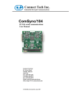
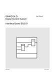
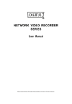
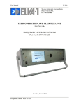
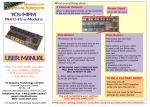
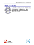
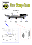
USER’S MANUAL
3
CHAPTER 3
SCC/ESCC ANCILLARY
SUPPORT CIRCUITRY
3.1 INTRODUCTION
The serial channels of the SCC are supported by ancillary
circuitry for generating clocks and performing data encoding and decoding. This chapter presents a description of
these functional blocks.
Note to SCC Users: The ancillary circuitry in the ESCC is
the same as in the SCC with the following noted changes.
The DPLL (Dual Phased-Locked Loop) output, when used
as the transmit clock source, has been changed to be free
of jitter. Consequently, this only affects the use of the DPLL
as the transmit clock source (it is typically used for the receive clock source), this has no effect on using the DPLL
as the receive clock source.
Note to ESCC/CMOS Users: The maximum input frequency to the DPLL has been specified as two times the
PCLK frequency (Spec #16b TxRX(DPLL)). There are no
changes to the baud rate generators from the NMOS to the
CMOS/ESCC.
3.2 BAUD RATE GENERATOR
The Baud Rate Generator (BRG) is essential for
asynchronous communications. Each channel in the SCC
contains a programmable baud rate generator. Each
generator consists of two 8-bit, time-constant registers
forming a16-bit time constant, a 16-bit down counter, and
a flip-flop on the output so that it outputs a square wave.
On start-up, the flip-flop on the output is set High, so that it
starts in a known state, the value in the time-constant
register is loaded into the counter, and the counter begins
counting down. When a count of zero is reached, the
output of the baud rate generator toggles, the value in the
time-constant register is loaded into the counter, and the
process starts over. The programmed time constant is
read from RR12 and RR13. A block diagram of the baud
rate generator is shown in Figure 3-1.
WR12
WR 13
Zero
Count
16-Bit Counter
/RTxC Pin
PCLK Pin
Baud Rate
Generator
Clock
(Takes One More
Clock to Load
Time Constant
Value to
Counter
÷2
Output
÷Clock
Mode
(Gives one Transition
Each Time the Counter
Counts to Zero)
(May Provide
Higher Resolution
to Sample Data)
Desired Baud
(Asynchronous Mode)
Figure 3-1. Baud Rate Generator
3-1
SCC™/ESCC™ User’s Manual
SCC/ESCC Ancillary Support Circuitry
3.2 BAUD RATE GENERATOR (Continued)
The time-constant can be changed at any time, but the
new value does not take effect until the next load of the
counter (i.e., after zero count is reached).
No attempt is made to synchronize the loading of a new
time-constant with the clock used to drive the generator.
When the time-constant is to be changed, the generator
should be stopped first by writing WR14 D0=0. After loading
the new time constant, the BRG can be started again. This
ensures the loading of a correct time constant, but loading
does not take place until zero count or a reset occurs.
If neither the transmit clock nor the receive clock are programmed to come from the /TRxC pin, the output of the
baud rate generator may be made available for external
use on the /TRxC pin.
Note: This feature is very useful for diagnostic purposes.
By programming the output of the baud rate generator as
output on the /TRxC pin, the BRG is source and time tested, and the programmed time constant verified.
The clock source for the baud rate generator is selected by
bit D1 of WR14. When this bit is set to 0, the BRG uses the
signal on the /RTxC pin as its clock, independent of whether the /RTxC pin is a simple input or part of the crystal oscillator circuit. When this bit is set to 1, the BRG is clocked
by the PCLK. To avoid metastable problems in the
counter, this bit should be changed only while the baud
rate generator is disabled, since arbitrarily narrow pulses
can be generated at the output of the multiplexer when it
changes status.
The BRG is enabled while bit D0 of WR14 is set to 1. It is
disabled while WR14 D0=0 and after a hardware reset (but
not a software reset). To prevent metastable problems
when the baud rate generator is first enabled, the enable
bit is synchronized to the baud rate generator clock. This
introduces an additional delay when the baud rate
generator is first enabled (Figure 3-2). The baud rate
generator is disabled immediately when bit D0 of WR14 is
set to 0, because the delay is only necessary on start-up.
The baud rate generator is enabled and disabled on the fly,
but this delay on start-up must be taken into consideration.
Figure 3-2. Baud Rate Generator Start Up
3-2
SCC™/ESCC™ User’s Manual
SCC/ESCC Ancillary Support Circuitry
The formulas relating the baud rate to the time-constant
and vice versa are shown below.
Time Constant =
Baud Rate =
Clock Frequency
-2
2 x (Clock Mode) x (Baud Rate)
Clock Frequency
2 x (Clock Mode) x (Time Constant+ 2)
In these formulas, the BRG clock frequency (PCLK or
/RTxC) is in Hertz, the desired baud rate in bits/sec, Clock
Mode is 1 in sync modes, 1, 16, 32 or 64 in async mode
and the time constant is dimensionless. The example in
Table 3-1 assumes a 2.4576 MHz clock (from /RTxC) factor of 16 and shows the time constant for a number of popular baud rates.
For example:
6
TC =
106
2.4576 x 10
(2 x 16) x 150
.
-2 = 510
Table 3-1. Baud Rates for 2.4576 MHz Clock and 16x
Clock Factor
Baud
Rate
38400
19200
9600
4800
2400
1200
600
300
150
3
Time Constant
Decimal
0
2
6
14
30
62
126
254
510
Hex
0000
0002
0006
000E
001E
003E
007E
00FE
01FE
Other commonly used clock frequencies include 3.6846,
4.6080, 4.91520, 6.144, 7.3728, 9.216, 9.8304, 12.288,
14.7456, 19.6608 (units in MHz).
Initializing the BRG is done in three steps. First, the timeconstant is determined and loaded into WR12 and WR13.
Next, the processor must select the clock source for the
BRG by setting bit D1 of WR14. Finally, the BRG is enabled by setting bit D0 of WR14 to 1.
Note: The first write to WR14 is not necessary after a hardware reset if the clock source is the /RTxC pin. This is because a hardware reset automatically selects the /RTxC
pin as the BRG clock source.
3-3
SCC™/ESCC™ User’s Manual
SCC/ESCC Ancillary Support Circuitry
3.3 DATA ENCODING/DECODING
Data encoding is utilized to allow the transmission of clock
and data information over the same medium. This saves
the need to transmit clock and data over separate medium
as would normally be required for synchronous data. The
SCC provides four different data encoding methods,
selected by bits D6 and D5 in WR10. An example of these
DATA
1
1
0
0
four encoding methods is shown in Figure 3-3. Any
encoding method is used in any X1 mode in the SCC,
asynchronous or synchronous. The data encoding
selected is active even though the transmitter or receiver
is idling or disabled.
1
0
High = 1
Low = 0
NRZ
No Change = 1
Change = 0
NRZI
Bit Center Transition:
Transition = 1
No Transition = 0
FM1
(Biphase Mark)
FM0
(Biphase Space)
No Transition = 1
Transition = 0
MANCHESTER
High → Low = 1
Low → High = 0
Figure 3-3. Data Encoding Methods
3-4
Bit Cell Level:
SCC™/ESCC™ User’s Manual
SCC/ESCC Ancillary Support Circuitry
NRZ (Non-Return to Zero). In NRZ, encoding a 1 is represented by a High level and a 0 is represented by a Low
level. In this encoding method, only a minimal amount of
clocking information is available in the data stream in the
form of transitions on bit-cell boundaries. In an arbitrary
data pattern, this may not be sufficient to generate a clock
for the data from the data itself.
FM1 (Bi-phase Mark). In FM1 encoding, also known as biphase mark, a transition is present on every bit cell boundary, and an additional transition may be present in the middle of the bit cell. In FM1, a 0 is sent as no transition in the
center of the bit cell and a 1 is sent as a transition in the
center of the bit cell. FM1 encoded data contains sufficient
information to recover a clock from the data.
NRZI (Non-Return to Zero Inverted). In NRZI, encoding
a 1 is represented by no change in the level and a 0 is represented by a change in the level. As in NRZ, only a minimal amount of clocking information is available in the data
stream, in the form of transitions on bit cell boundaries. In
an arbitrary data pattern this may not be sufficient to generate a clock for the data from the data itself. In the case
of SDLC, where the number of consecutive 1s in the data
stream is limited, a minimum number of transitions to generate a clock are guaranteed.
FM0 (Bi-phase Space). In FM0 encoding, also known as
bi-phase space, a transition is present on every bit cell
boundary and an additional transition may be present in
the middle of the bit cell. In FM0, a 1 is sent as no transition
in the center of the bit cell and a 0 is sent as a transition in
the center of the bit cell. FM0 encoded data contains sufficient information to recover a clock from the data.
ESCC:
TxD Pin Forced High in SDLC feature. When the ESCC
is programmed for SDLC mode with NRZI data encoding and mark idle (WR10 D6=0, D5=1, D3=1), the TxD
pin is automatically forced high when the transmitter
goes to the mark idle state. There are several different
ways for the transmitter to go into the idle state. In
each of the following cases the TxD pin is forced high
when the mark idle condition is reached: data, CRC,
flag and idle; data, flag and idle; data, abort (on underrun) and idle; data, abort (command) and idle; idle flag
and command to idle mark. The Force High feature is
disabled when the mark idle bit is reset. The TxD pin is
forced High on the falling edge of the TxC cycle after
the falling edge of the last bit of the closing flag. Using
SDLC Loop mode is independent of this feature.
Manchester (Bi-phase Level). Manchester (bi-phase level) encoding always produces a transition at the center of
the bit cell. If the transition is Low to High, the bit is 0. If the
transition is High to Low, the bit is 1. Encoding of Manchester format requires an external circuit consisting of a ‘D’
flip-flop and four gates (Figure 3-4). The SCC is used to
decode Manchester data by using the DPLL in the FM
mode and programming the receiver for NRZ data (See
Section 3.1.3).
Data Encoding Initialization. The data encoding method is
selected in the initialization procedure before the transmitter
and receiver are enabled, but no other restrictions apply.
Note that in NRZ and NRZI, the receiver samples the data
only on one edge, as shown in Figure 3-3. However, in FM1
and FM0, the receiver samples the data on both edges.
Also, as shown in Figure 3-3, the transmitter defines bit cell
boundaries by one edge in all cases and uses the other
edge in FM1 and FM0 to create the mid-bit transition.
This feature is used in combination with the automatic
SDLC opening flag transmission feature, WR7' D0=1,
to assure that data packets are properly formatted.
Therefore, when these features are used together, it is
not necessary for the CPU to issue any commands
when using the force idle mode in combination with
NRZI data encoding. If WR7' D0 is reset, like the SCC,
it is necessary to reset the mark idle bit (WR10 D2) to
enable flag transmission before an SDLC packet is
transmitted.
3-5
3
SCC™/ESCC™ User’s Manual
SCC/ESCC Ancillary Support Circuitry
3.3 DATA ENCODING/DECODING (Continued)
NRZ
3
b
a
1
4
2
Transmit Clock
Transmit
Clock
NRZ
1
2
3
4
5
Figure 3-4. Manchester Encoding Circuit
3-6
5
Manchester
SCC™/ESCC™ User’s Manual
SCC/ESCC Ancillary Support Circuitry
3.4 DPLL DIGITAL PHASE-LOCKED LOOP
Each channel of the SCC contains a digital phase-locked
loop that can be used to recover clock information from a
data stream with NRZI, FM, NRZ, or Manchester encoding. The DPLL is driven by a clock nominally at 32 (NRZI)
or 16 (FM) times the data rate. The DPLL uses this clock,
along with the data stream, to construct a receive clock for
the data. This clock can then be used as the SCC receive
clock, the transmit clock, or both.
RxD
Edge Detector
Figure 3-5 shows a block diagram of the digital phaselocked loop. It consists of a 5-bit counter, an edge detector,
and a pair of output decoders. The clock for the DPLL
comes from the output of a two-input multiplexer, and the
two outputs go to the transmitter and receive clock
multiplexers. The DPLL is controlled by seven commands
encoded in WR14 bits D7, D6 and D5.
Count Modifier
Decode
Receive
Clock
5-Bit Counter
Decode
Transmit
Clock
Figure 3-5. Digital Phase-Locked Loop
The clock source for the DPLL is selected issuing one of
the two commands in WR14, that is:
WR14 (7-5) = 100 selects the BRG
WR14 (7-5) = 101 selects the /RTxC pin
The first command selects the baud rate generator as the
clock source. The other command selects the /RTxC pin
as the clock source, independent of whether the /RTxC pin
is a simple input or part of the crystal oscillator circuit.
Initialization of the DPLL is done at any time during the initialization sequence, but should be done after the clock
modes have been selected in WR11, and before the receiver and transmitter are enabled. When initializing the
DPLL, the clock source should be selected first, followed
by the selection of the operating mode.
To avoid metastable problems in the counter, the clock
source selection is made only while DPLL is disabled,
since arbitrarily narrow pulses are generated at the output
of the multiplexer when it changes status.
The DPLL is programmed to operate in one of two modes,
as selected by commands in WR14.
As in the case of the clock source selection, the mode of
operation is only changed while the DPLL is disabled to
prevent unpredictable results.
In the NRZI mode, the DPLL clock must be 32 times the
data rate. In this mode, the transmit and receive clock outputs of the DPLL are identical, and the clocks are phased
so that the receiver samples the data in the middle of the
bit cell. In NRZI mode, the DPLL does not require a transition in every bit cell, so this mode is useful for recovering
the clocking information from NRZ and NRZI data streams.
In the FM mode, the DPLL clock must be 16 times the data
rate. In this mode, the transmit clock output of the DPLL
lags the receive clock outputs by 90 degrees to make the
transmit and receive bit cell boundaries the same, because the receiver must sample FM data at one-quarter
and three-quarters bit time.
The DPLL is enabled by issuing the Enter Search Mode
command in WR14; that is WR14 (7-5) = 001. The Enter
Search Mode command unlocks the counter, which is held
while the DPLL is disabled, and enables the edge detector.
If the DPLL is already enabled when this command is issued, the DPLL also enters Search Mode.
WR14 (7-5) = 111 selects NRZI mode
WR14 (7-5) = 110 selects FM mode
Note: A channel or hardware reset disables the DPLL, selects the /RTxC pin as the clock source for the DPLL, and
places it in the NRZI mode.
3-7
3
SCC™/ESCC™ User’s Manual
SCC/ESCC Ancillary Support Circuitry
3.4 DPLL DIGITAL PHASE-LOCKED LOOP (Continued)
3.4.1 DPLL Operation in the NRZI Mode
To operate in NRZI mode, the DPLL must be supplied with
a clock that is 32 times the data rate. The DPLL uses this
clock, along with the receive data, to construct receive and
transmit clock outputs that are phased to properly receive
and transmit data.
To do this, the DPLL divides each bit cell into four regions,
and makes an adjustment to the count cycle of the 5-bit
counter dependent upon the region a transition on the receive data input occurred (Figure 3-6).
Ordinarily, a bit-cell boundary occurs between count 15
and count 16, and the DPLL output causes the data to be
sampled in the middle of the bit cell. However, four different situations can occur:
If the bit-cell boundary (from space to mark) occurs anywhere during the second half of count 15 or the first half of
count 16, the DPLL allows the transition without making a
correction to its count cycle.
If the bit cell boundary (from space to mark) occurs between the middle of count 16 and count 31, the DPLL is
sampling the data too early in the bit cell. In response to
this, the DPLL extends its count by one during the next 0
to 31 counting cycle, which effectively moves the edge of
the clock that samples the receive data closer to the center
of the bit cell.
If the transition occurs between count 0 and the middle of
count 15, the output of the DPLL is sampling the data too
late in the bit cell. To correct this, the DPLL shortens its
count by one during the next 0 to 31 counting cycle, which
effectively moves the edge of the clock that samples the
receive data closer to the center of the bit cell.
If the DPLL does not see any transition during a counting cycle, no adjustment is made in the following counting cycle.
If an adjustment to the counting cycle is necessary, the
DPLL modifies count 5, either deleting it or doubling it.
Thus, only the Low time of the DPLL output is lengthened
or shortened.
Bit Cell
Count
16 17 18 19 20 21 22 23 24 25 26 27 28 29 30 31 0
Correction
1
2
Add One Count
3
4
5
6
7
8
9 10 11 12 13 14 15
Subtract One Count
No Change
No Change
DPLL Out
Figure 3-6. DPLL in NRZI Mode
While the DPLL is in search mode, the counter remains at
count 16, where the DPLL outputs are both High. The
missing clock latches in the DPLL, which may be accessed
3-8
in RR10, are not used in NRZI mode. An example of the
DPLL in operation is shown in Figure 3-7.
SCC™/ESCC™ User’s Manual
SCC/ESCC Ancillary Support Circuitry
Receive
Data
3
DPLL
Output
Correction
Windows
+1
Count
Length
32
-1
+1
32
-1
+1
32
-1
+1
31
-1
31
+1
-1
+1
-1
31
+1
-1
33
+1
33
-1
+1
33
Figure 3-7. DPLL Operating Example (NRZI Mode)
3.4.2 DPLL Operation in the FM Modes
To operate in FM mode, the DPLL must be supplied with a
clock that is 16 times the data rate. The DPLL uses this
clock, along with the receive data, to construct, receive,
and transmit clock outputs that are phased to receive and
transmit data properly.
In FM mode, the counter in the DPLL counts from 0 to 31,
but now each cycle corresponds to 2-bit cells. To make
adjustments to remain in phase with the receive data, the
DPLL divides a pair of bit cells into five regions, making the
adjustment to the counter dependent upon which region the
transition on the receive data input occurred (Figure 3-8).
Bit Cell
Count
Correction
16 17 18 19 20 21 22 23 24 25 26 27 28 29 30 31 0
+1
1
2
3
4
5
Ignored
No Change
6
7
8
9 10 11 12 13 14 15
+1
No Change
RX DPLL Out
TX DPLL Out
Figure 3-8. DPLL Operation in the FM Mode
3-9
SCC™/ESCC™ User’s Manual
SCC/ESCC Ancillary Support Circuitry
3.4 DPLL DIGITAL PHASE-LOCKED LOOP (Continued)
In FM mode, the transmit clock and receive clock outputs
from the DPLL are not in phase. This is necessary to make
the transmit and receive bit cell boundaries coincide, since
the receive clock must sample the data one-fourth and
three-fourths of the way through the bit cell.
Ordinarily, a bit cell boundary occurs between count 15 or
count 16, and the DPLL receive output causes the data to
be sampled at one-fourth and three-fourths of the way
through the bit cell.
However, four variations can occur:
If the bit-cell boundary (from space to mark) occurs anywhere during the second half of count 15 or the first half of
count 16, the DPLL allows the transition without making a
correction to its count cycle.
If the bit-cell boundary (from space to mark) occurs between the middle of count 16 and the middle of count 19,
the DPLL is sampling the data too early in the bit cell. In
response to this, the DPLL extends its count by one during
the next 0 to 31 counting cycle, which effectively moves
the receive clock edges closer to where they should be.
Any transitions occurring between the middle of count 19
in one cycle and the middle of count 12 during the next cycle are ignored by the DPLL. This guarantees that any data
transitions in the bit cells do not cause an adjustment to the
counting cycle.
If no transition occurs between the middle of count 12 and
the middle of count 19, the DPLL is probably not locked
onto the data properly. When the DPLL misses an edge,
the One Clock Missing bit is RR10, it is set to 1 and
latched. It will hold this value until a Reset Missing Clock
command is issued in WR14, or until the DPLL is disabled
or programmed to enter the Search mode. Upon missing
this one edge, the DPLL takes no other action and does
not modify its count during the next counting cycle.
If the DPLL does not see an edge between the middle of
count 12 and the middle of count 19 in two successive 0 to
31 count cycles, a line error condition is assumed. If this
occurs, the Two Clocks Missing bit in RR10 is set to 1 and
latched. At the same time, the DPLL enters the Search
mode. The DPLL makes the decision to enter the Search
mode during count 2, where both the receive clock and
transmit clock outputs are Low. This prevents any glitches
on the clock outputs when the Search mode is entered.
While in the Search mode, no clock outputs are provided
by the DPLL. The Two Clocks Missing bit in RR10 is
latched until a Reset Missing Clock command is issued in
WR14, or until the DPLL is disabled or programmed to enter the Search mode.
3-10
While the DPLL is disabled, the transmit clock output of the
DPLL may be toggled by alternately selecting FM and
NRZI mode in the DPLL. The same is true of the receive
clock.
While the DPLL is in the Search mode, the counter remains at count 16 where the receive output is Low and the
transmit output is Low. This fact is used to provide a transmit clock under software control since the DPLL is in the
Search mode while it is disabled.
As in NRZI mode, if an adjustment to the counting cycle is
necessary, the DPLL modifies count 5, either deleting it or
doubling it. If no adjustment is necessary, the count sequence proceeds normally.
When the DPLL is programmed to enter Search mode,
only clock transitions should exist on the receive data pin.
If this is not the case, the DPLL may attempt to lock on to
the data transitions. If the DPLL does lock on to the data
transitions, then the Missing Clock condition will inevitably
occur because data transitions are not guaranteed every
bit cell.
To lock in the DPLL properly, FM0 encoding requires continuous 1s received when leaving the Search mode. In
FM1 encoding, continuous 0s are required; with Manchester encoded data this means alternating 1s and 0s. With all
three of these data encoding methods there is always at
least one transition in every bit cell, and in FM mode the
DPLL is designed to expect this transition.
3.4.3 DPLL Operation in the Manchester
Mode
The SCC can be used to decode Manchester data by using the DPLL in the FM mode and programming the receiver for NRZ data. Manchester encoded data contains a
transition at the center of every bit cell; it is the direction of
this transition that distinguishes a 1 from a 0. Hence, for
Manchester data, the DPLL should be in FM mode (WR14
command D7=1, D6=1, D5=0), but the receiver should be
set up to accept NRZ data (WR10 D6=0, D5=0).
3.4.4 Transmit Clock Counter (ESCC only)
The ESCC includes a Transmit Clock Counter which parallels the DPLL. This counter provides a jitter-free clock
source to the transmitter by dividing the DPLL clock source
by the appropriate value for the programmed data encoding format as shown in Figure 3-9. Therefore, in FM mode
(FM0 or FM1), the counter output is the input frequency divided by 16. In NRZI mode, the counter frequency is the input divided by 32. The counter output replaces the DPLL
transmit clock output, available as the transmit clock
source. This has no effect on the use of the DPLL as the
receive clock source.
SCC™/ESCC™ User’s Manual
SCC/ESCC Ancillary Support Circuitry
The output of the transmit clock derived from this counter
is available to the /TRxC pin when the DPLL output is
selected as the transmit clock source. Care must be taken
using ESCC in SDLC Loop mode with the DPLL. The
SDLC Loop mode requires synchronized Tx and Rx
DPLL CLK
Input
clocks, but the ESCC’s DPLL might be off-sync because of
this Transmit Clock Counter. In SDLC Loop, one should
instead echo the signal of the RxDPLL out to clock the
receiver and transmitter to achieve synchronization. This
can be programmed via bits D1-D0 in WR11.
DPLL
DPLL Output to Receiver
DPLL Counter
DPLL Output to Transmitter
Input Divided by 16 (FM0 or FM1)
Input Divided by 32 for NRZI
Figure 3-9. DPLL Transmit Clock Counter Output (ESCC only)
3.5 CLOCK SELECTION
The SCC can select several clock sources for internal and
external use. Write Register 11 is the Clock Mode Control
register for both the receive and transmit clocks. It determines the type of signal on the /SYNC and /RTxC pins and
the direction of the /TRxC pin.
The SCC is programmed to select one of several sources
to provide the transmit and receive clocks.
The source of the receive clock is controlled by bits D6 and
D5 of WR11. The receive clock may be programmed to
come from the /RTxC pin, the /TRxC pin, the output of the
baud rate generator, or the receive output of the DPLL.
The source of the transmit clock is controlled by bits D4
and D3 of WR11. The transmit clock may be programmed
to come from the /RTxC pin, the /TRxC pin, the output of
the baud rate generator, or the transmit output of the
DPLL.
Ordinarily, the /TRxC pin is an input, but it can become an
output if this pin has not been selected as the source for
the transmitter or the receiver, and bit D2 of WR11 is set
to 1. The selection of the signal provided on the /TRxC output pin is controlled by bits D1 and D0 of WR11. The
/TRxC pin is programmed to provide the output of the crystal oscillator, the output of the baud rate generator, the receive output of the DPLL or the actual transmit clock. If the
output of the crystal oscillator is selected, but the crystal
oscillator has not been enabled, the /TRxC pin is driven
High. The option of placing the transmit clock signal on the
/TRxC pin when it is an output allows access to the transmit output of the DPLL.
to the multiplexer section, as well as the various signal inversions that occur in the paths to the outputs.
Selection of the clocking options may be done anywhere in
the initialization sequence, but the final values must be selected before the receiver, transmitter, baud rate generator, or DPLL are enabled to prevent problems from arbitrarily narrow clock signals out of the multiplexers. The
same is true of the crystal oscillator, in that the output
should be allowed to stabilize before it is used as a clock
source.
Also shown are the edges used by the receiver, transmitter, baud rate generator and DPLL to sample or send data
or otherwise change state. For example, the receiver samples data on the falling edge, but since there is an inversion in the clock path between the /RTxC pin and the receiver, a rising edge of the /RTxC pin samples the data for
the receiver.
The following shows three examples for selecting different
clocking options. Figure 3-11 shows the clock set up for
asynchronous transmission, 16x clock mode using the onchip oscillator with an external crystal. This example uses
the oscillator as the input to the baud rate generator, although it can be used directly as the transmit or receive clock
source. The registers involved are WR11 through WR14 and
the figure shows the programming in these registers.
An example of asynchronous communication where a 1x
clock is obtained from an external MODEM is shown in
Figure 3-12. The data encoding is NRZ. Note that:
1. The BRG is not used under this configuration.
Figure 3-10 shows a simplified schematic diagram of the
circuitry used in the clock multiplexing. It shows the inputs
3-11
3
SCC™/ESCC™ User’s Manual
SCC/ESCC Ancillary Support Circuitry
3.5 CLOCK SELECTION (Continued)
2. The x1 mode in Asynchronous mode is a combination
of both synchronous and asynchronous transmission.
The data is clocked by a common timing base, but
characters are still framed with Start and Stop bits.
Because the receiver waits for one clock period after
detecting the first High-to-Low transition before
beginning to assemble characters, the data and clock
is synchronized externally. The x1 mode is the only
mode in which a data encoding method other than
NRZ is used.
OSC
RX
/SYNC
Receiver
OSC
/RTxC
TX
/TRxC
Transmitter
Echo
DPLL
Baud Rate
Generator Out
Echo
DPLL
Tx DPLL Out
BRG
Rx DPLL Out
Baud Rate
Generator
PCLK
Figure 3-10. Clock Multiplexer
3-12
SCC™/ESCC™ User’s Manual
SCC/ESCC Ancillary Support Circuitry
External
Crystal
3
/SYNC Pin
B
R
G
16x
Output
TxC
RxC
/RTxC Pin
/TRxC Pin
SCC
Figure 3-11. Async Clock Setup Using an External Crystal
WR11
D7
1
WR14
D0
1
0
1
0
1
1
D1
0
0
/TRxC OUT = BRG Output
BRG Clock Source = /RTXC
or XTAL OSCILLATOR
/TRxC Pin = Output Pin
Tx Clock = BRG Output
Rx Clock = BRG Output
Using External Crystal
NRZ Data
SYNC
Modem
TxC
1x
RxD Pin
/RTxC Pin
RxC
SCC
Figure 3-12. Clock Source Selection
3-13
SCC™/ESCC™ User’s Manual
SCC/ESCC Ancillary Support Circuitry
3.6 CRYSTAL OSCILLATOR (Continued)
Figure 3-13 shows the use of the DPLL to derive a 1x clock
from the data. In this example:
The DPLL clock output = RxC (receiver clock) WR11.
Set FM mode WR14.
The DPLL clock input = BRG output (x16 the data rate)
WR14.
External
Crystal
Set FM mode WR10.
/SYNC Pin
B
R
G
/RTxC Pin
RxD Pin
16x Data Rate
D
P
L
L
RxC
TxC
RxD
Figure 3-13. Synchronous Transmission, 1x Clock Rate, FM Data Encoding, using DPLL
3.6 CRYSTAL OSCILLATOR
Each channel contains a high gain oscillator amplifier for
use with an external crystal circuit. The amplifier is available between the /RTxC pin (crystal input) and the /SYNC
pin (crystal output) for each channel.
The oscillator amplifier is enabled by writing WR11 D7=1.
While the crystal oscillator is enabled, anything that has
selected the /RTxC pin as its clock source automatically
connects to the output of the crystal oscillator.
Note: The output of the oscillator amplifier can be programmed to output on the /TRxC pin, which is particularly
valuable for diagnostic purposes. Because amplifier characteristics can be affected by the impedance of measurement equipment applied directly to the crystal circuit, using
the /TRxC pin allows the oscillation to be tested without affecting the circuit.
3-14
Of course, since the oscillator uses the /RTxC and /SYNC
pins, this precludes the use of these pins for other functions. In synchronous modes, no sync pulse is output, and
the External Sync mode cannot be selected. In asynchronous modes, the state of the Sync/Hunt bit in RR0 is no
longer controlled by the /SYNC pin. Instead, the Sync/Hunt
bit is forced to 0.
The crystal oscillator requires some finite time to stabilize
and must be allowed to stabilize before it is used as a clock
source. This stabilization time is dependent on the external
circuit impedance and 20 ms is a suggested minimum. The
External Crystal should operate in parallel resonance. For
further details on designing with the crystal, refer to Appendix A, “On-Chip Oscillator Design”.