1
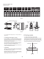
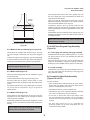
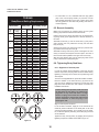
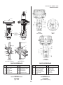
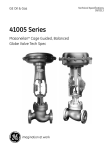
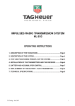
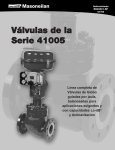
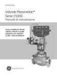
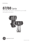
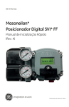
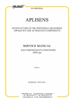
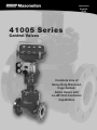
Instructions EH41005 07/02 41005 Series Control Valves Complete Line of Heavy Duty, Balanced, Cage Guided, Globe Valves with Lo-dB®/Anti-Cavitation Capabilities Instruction No. EH3600 – 07/02 41005 Series Valves TABLE OF CONTENTS 1 - GENERAL .....................................................................3 6 - VALVE REASSEMBLY .................................................7 1.1. SCOPE ........................................................................................3 6.1 PINNING THE VALVE PLUG STEM ............................................7 6.1.1. Reference marking on the valve plug stem ....................7 6.1.2. Screwing in the valve plug stem ......................................7 6.1.3. Drilling pin hole .................................................................8 6.1.4. Pinning ...............................................................................8 1.2. SERIAL PLATE ...........................................................................3 1.3. AFTER SALES SERVICE ...........................................................3 1.4. SPARE PARTS ............................................................................3 6.2. SEAL RING ASSEMBLY .................................................................8 6.2.1. Model 41305 ......................................................................8 6.2.2. Models 41405 and 41505...................................................9 6.2.3. Model 41605 ......................................................................9 6.2.4. Model 41905 ......................................................................9 1.5. ACTUATOR AND ACCESSORIES .............................................3 2 - NUMBERING SYSTEM.................................................3 3 - INSTALLATION .............................................................4 6.3. 41405 VALVE PLUG AND CAGE ASSEMBLY ..........................9 6.3.1. Valve plug and auxiliary pilot plug assembly ................9 6.3.2. Cage assembly .................................................................9 3.1. PIPING CLEANLINESS ..............................................................4 3.2. ISOLATION BYPASS VALVE......................................................4 6.4. COMPLETING VALVE BODY ASSEMBLY .........................................9 3.3. HEAT INSULATION.....................................................................4 6.5. BONNET ASSEMBLY .........................................................................10 3.4. HYDRAULIC TEST AND CLEANING OF LINES .......................4 6.6. TIGHTENING BODY STUD NUTS......................................................10 6.6.1. Alignment of internal parts ...........................................10 3.5. FLOW DIRECTION......................................................................4 6.7. PACKING BOX ASSEMBLY ...............................................................11 4 - DISASSEMBLY .............................................................4 4.1. ACTUATOR REMOVAL ..............................................................4 4.1.1. Disconnect instruments ...................................................4 4.1.2. Plug stems screwed into the actuator stem ...................4 4.1.3. Stems attached with a stem connector...........................4 4.1.4. Actuator removal ..............................................................4 7 - ACTUATOR .................................................................11 7.1. CONNECTING TYPE 88 NO. 6 ACTUATOR.............................11 7.2. CONNECTING TYPE 87 NO. 6 ACTUATOR.............................11 7.3. CONNECTING TYPE 87 NO. 10, 16 AND 23 ACTUATORS.....11 4.2. OPENING PRESSURIZED CHAMBER ......................................4 7.4. CONNECTING TYPE 88 NO. 10, 16 AND 23 ACTUATORS.....12 4.3. PLUG STEM DISASSEMBLY ....................................................5 7.5. CONNECTING TYPE 37 ACTUATOR.......................................12 4.4. AUXILIARY PILOT PLUG DISASSEMBLY ...............................5 7.6. CONNECTING TYPE 38 ACTUATOR.......................................12 FIGURE OF BODY SUB ASSEMBLY.................................................13-14 5 - MAINTENANCE - REPAIR............................................5 FIGURE OF ACTUATOR..........................................................................15 5.1. PACKING BOX ............................................................................5 5.1.1. PTFE packing ..................................................................................5 5.1.2. Graphite packing ..............................................................6 MASONEILAN DIRECT SALES OFFICES..........................BACK COVER 5.2. REPAIR OF PARTS.....................................................................6 5.2.1. Guiding surfaces ...............................................................6 5.2.2. Seating surfaces................................................................6 5.2.3. Gasket seating surfaces ...................................................7 5.2.4. Seal rings and gaskets .....................................................7 5.2.5. Valve plug and stem..........................................................7 2 Instruction No. EH3600 – 07/02 41005 Series Valves IMPORTANT This document contains all the instructions required for the installation, operation and maintenance of the equipment. Regular maintenance, strict observance of these instructions and the use of manufacturer’s replacement parts will guarantee optimum operation and reduce maintenance costs. and repair of its equipment. Contact the local Masoneilan representative or Masoneilan factory located closest to you. 1. General 1.1. Scope 1.4. Spare parts The following instructions are designed to guide the user through the installation and maintenance of the 41005 series cage-guided valves for all sizes and pressure classes. Only Masoneilan replacement parts should be used when carrying out maintenance operations. Obtain replacement parts through our local representatives or Spare Parts Department. This instruction manual describes all the standard options in the 41005 valve series. Special supplements or addendums to this instruction manual may be required for special designs developed to meet specific customer requirements. When ordering spare parts, the model and serial numbers indicated on the manufacturer’s serial plate must be given. The recommended spare parts are indicated in the parts list included in this instruction manual. 1.2. Serial plate 1.5. Actuator and accessories The serial plate is usually fixed to the side of the actuator yoke. It indicates, amongst other things, the size and type of valve, the pressure class, the body and bonnet material, and the maximum supply pressure of the actuator. The valve is typically equipped with an actuator. Actuators and other valves accessories have their own instruction manuals, which provides information on the electric and pneumatic connections. The instruction manuals to be used for standard actuators are ER3000 for type 37/38 and ER8788 for type 87/88. 1.3. After Sales Service Masoneilan offers After Sales Service comprised of highly qualified technicians to support the operation, maintenance 2. Numbering System 1st 2nd 1st 2nd 3rd 4th 5th 4 1 0 0 5 Actuator Type* Body Series 37 Spring Diaphragm : direct, air to close (fail open action) 38 Spring Diaphragm : reverse, air to open (fail to close) 41 Cage Guided, Balanced Globe 84 Cylinder : spring return, direct, air to close, single or double-acting (fail open action) 85 Cylinder : spring return, reverse, air to open, single or double-acting (fail to close) 86 Cylinder : double-acting, without spring, air to open or air to close action 87 Spring Diaphragm : direct, air to close (fail open action) 88 Spring Diaphragm : reverse, air to open (fail close action) Seal Type 0. 3. 4. 5. 6. 9. Undefined Pressure Energized PTFE Seal Ring Auxiliary Shut-off Plug (Pilot) Metal Seal Ring PTFE Seal Ring Graphite Seal Ring 6th Trim Type/Characteristic 0. 1. 2. 3. 4. 5. 6. 7. 8. 9. Undefined Standard Cage/Linear Standard Cage/Equal % Lo-dB®/Anti-Cav Single Stage/Linear Lo-dB/Anti-Cav Single Stage with Diffuser/Linear Lo-dB Multi-Stage/Linear Design Series Optional Config. 5 A Angle Body VRT (stack) Type S/Linear VRT (partial stack) Type S/Modified VRT (cage) Type C/Linear Anti-Cav Multi-Stage/ Linear * Refer to applicable product instructions manual for cylinder type actuator. Engineered trim options are also available for high temperature and high pressure drop applications, including Multi-Stage Anti-Cavitation Trim. Please consult factory for details. 3 Instruction No. EH3600 – 07/02 41005 Series Valves 3. Installation Caution: During this operation, make sure that the plug does not turn when it is seated. If the plug travel is very small and there is a large amount of plug stem inside the actuator, it may be necessary to remove the yoke nut and lift the actuator so that the plug is not touching the seat. 3.1. Piping cleanliness Before installing the valve in the line, clean piping and valve of all foreign material such as welding chips, scale, oil, grease or dirt. Gasket mating surfaces must be thoroughly cleaned to insure leak-free joints. 4.1.3. Stems attached with a stem connector 3.2. Isolation bypass valve For air-to-retract actuators, apply sufficient air pressure on the actuator to retract the stem completely. Loosen the screws and remove the stem connector. To allow for in-line inspection, maintenance and removal of the valve without service interruption, provide a manually operated shutoff valve on each side of the control valve and a manually operated throttling valve in the bypass line. Caution: Prior to disassembly, vent the process pressure and isolate the valve if necessary. 3.3. Heat insulation In case of a heat-insulated installation, do not insulate the valve bonnet and take protective measures relative to personal safety. 4.1.4 Actuator removal 3.4. Hydraulic test and cleaning of lines Disconnect all the air and electrical connections from and to the actuator. Loosen the yoke nut or attachment screws and lift the actuator, making sure that the concentricity and/or the thread of the bonnet is not damaged. During this operation, the control valve must not be used as an isolating valve. This means that the valve must always be opened before carrying out pressure tests in the process line, cleaning of pipes, etc. Otherwise equipment damage or failure of the seal rings could result. 4.2. Opening pressurized chamber (Figures 14 and 15) 3.5. Flow direction The valve must always be reassembled with new packing sets and gaskets. Before disassembly, make sure that the appropriate parts are available. The valve must be installed so that the process fluid will flow through the valve in the direction indicated by the flow arrow located on the body. A. Remove the packing flange nuts (3) then remove the packing flange (4) and the packing follower (23). 4. Disassembly B. Check that the exposed part of the valve plug stem (1) is clean enough for the bonnet (7) to be removed easily. 4.1 Actuator removal (Figures 16 and 17) C. Remove the body stud nuts (8). Access to the internal components of the body should be accomplished with the actuator removed. To carry out this operation, follow the instructions below and refer to the specific actuator instructions (reference ER 8788 for type 87/88 actuators and ER 3000 for type 37/38 actuators). D. Lift the bonnet (7) up and disassemble it from the valve body (18). During this operation, the valve plug stem (1) must be pushed downwards so that the valve plug remains in the valve body (18). E. Remove the spring washer (17) or cage gasket (36) and the body gasket (10). 4.1.1 Disconnect instruments F. For Model 41305, 41505, 41605 and 41905 valves, remove the valve plug stem (1) and valve plug (15) assembly from the cage by pulling the valve plug stem upward. Then disassemble the cage (16) from the body (18). Disconnect all mechanical connections between the positioner and the other instruments. Disconnect the valve stem/actuator stem coupling as described in the following sections. 4.1.2 Plug stems screwed into the actuator stem Caution: Because of the piston seal ring, the cage may For air-to-retract actuators, apply sufficient air pressure to the actuator to retract the stem completely. be lifted along with the valve plug. If this should happen, press down on the cage so that it remains in the body. If the cage is lifted along with the valve plug, it could slip during handling and become damaged. 4 Instruction No. EH3600 – 07/02 41005 Series Valves 4.4. Auxiliary pilot plug disassembly (Model 41405 - Figure 14) G. In the case of a 41405 valve, remove the valve plug and body cage assembly by pulling the valve plug stem upward. In this design, the valve plug has a shoulder which prevents the cage from falling. Remove the valve plug from the cage by pushing on the end of the valve plug stem. For size 2", 3" or 4" (50, 80 or 100 mm) valves: H. Remove the seat ring (13) and the seat ring gasket (14) from the valve body (18). Exert a sufficient force on the auxiliary pilot plug (20) to compress the spring washers (12). The retaining ring (19) can then be removed, allowing for disassembly of the auxiliary pilot plug and spring washers. I. Remove the packing set (6), the packing spacer (5) For size 6" to 16" (150 to 400 mm) valves: and the guide bushing (22) from the bonnet (7). To carry out this operation safely, screws with diameters and lengths indicated in the table in figure 2 must be used. Thread the socket head cap screws through the holes in the auxiliary pilot plug (20). Tighten until the retaining ring (19) can be removed. Loosen the screws gradually, then remove the auxiliary pilot plug and the spring (12). Note: A packing spacer (5) is only required for a bonnet with a leak detector connection. 4.3. Plug stem disassembly (1) Pilot Dismounting Screw Sizes Length Diameter Qty. mm in. mm 150 2 2.25 57 1/4"- 20 UNC 2A Valve Size The valve plug stem is screwed and pinned into the valve plug (15). To disassemble the stem, the valve plug must be held as shown below, taking care not to damage the guiding surfaces. Disassemble the plug stem pin (9) from the assembly. By means of flats or using a nut and counter-nut on the end of the stem, unscrew the stem from the plug taking care not to apply a bending moment which could deform it. in. 6 8 200 2 2.75 70 10 250 2 2.50 63.5 12 300 3 4.00 101.5 16 400 3 2.50 63.5 3/8"- 16 UNC 2A Figure 2 5. Maintenance - Repair 5.1. Packing box Tight sealing within the packing box is obtained by compression of the packing (6). Compression must be achieved by evenly tightening the packing flange nuts (3) on the packing flange (4). Periodic re-tightening of the packing flange nuts is required to maintain proper sealing. Be careful not to over tighten the packing as this could prevent proper operation of the valve. If leakage persists after maximum packing compression, then the packing needs to be changed. Figure 1 A packing spacer (5) is only required for a bonnet with a leak detector connection. 5.1.1 PTFE packing Kevlar/PTFE, carbon/PTFE and pure PTFE packing rings are cut in such a way that they can be replaced without having to separate the valve plug stem from the actuator stem. A. Unscrew and remove the packing flange nuts (3). B. Lift the packing flange (4) and packing follower (23) up along the valve stem. 5 Instruction No. EH3600 – 07/02 41005 Series Valves C. By means of a puller, remove the packing (6) and packing spacer (5), being careful not to damage the sealing surface of the packing box or the valve plug stem. D. Replace new packing set (6): First assemble a back-up ring (Carbon/Graphite/Inconel braided ring). Then assemble the expanded graphite rings (smooth rings) in accordance with Figure 4. Finally, assemble an additional braided back-up ring. D. Replace the packing rings, placing the cut in each ring about 120° apart from the adjacent ring. Press rings in one at a time in accordance with the table in Figure 3. E. Reassemble the packing follower (23) and packing flange (4). F. Moderately tighten the packing flange nuts (3). PTFE Packing Number of Rings Valve Size G. Reassemble the valve plug stem to the actuator stem (see chapter on actuator reassembly). With Leak Detector H. Open and close the valve several times then tighten the packing as required. in. mm No Leak Detector 2 50 6 2 4 3 - 4 80 - 100 8 3 5 5.2. Repair of parts 6 - 16 150 - 500 7 2 5 Prior to reassembly, examine parts carefully for any scratches, unusual wear or other damage. On top of Under packing spacer packing spacer I. Put the valve back into service and check for leakage. Tighten packing flange nuts (3) as required. Figure 3 E. Reassemble the packing follower (23) and the packing flange (4). 5.2.1 Guiding surfaces Guiding surfaces of the cage, valve plug, guide bushing, plug stem, and auxiliary pilot plug must be checked. If there is only slight wear indications, then use a light abrasive to smooth out guiding surfaces. Otherwise the part must be replaced (see paragraph on spare parts). F. Tighten the packing flange nuts (3) without over compressing the packing rings. G. Put the valve back into service and check for leakage. Tighten packing flange nuts (3) as required. 5.1.2 Graphite packing To carry out this operation, the valve plug stem must be disconnected from the actuator stem. See chapter on actuator disassembly. Guiding surface Guiding surface A. Loosen and remove packing flange nuts (3) B. Remove packing flange (4) and packing follower (23) from the plug stem Pilot Seating surface C. Remove packing rings (6), being careful not to damage the sealing surface of the packing box or plug stem. Cage Graphite Packing Number of Rings Figure 5 5.2.2 Seating surfaces (Figure 6) Valve Size Braided Graphite Braided 1 4 1 3 - 4 80 - 100 1 6 1 6 - 16 150 - 500 1 4 1 in. mm 2 50 If the surface of the auxiliary pilot plug (20) is damaged, the auxiliary pilot plug must be replaced (see paragraph on spare parts). The seat ring seating surface (13), valve plug seating surfaces (15) and the auxiliary pilot plug seat (20) must be completely free of dents, wear and scratches. Any seating surfaces showing signs of slight deterioration may be touched up on a lathe in accordance with the following guidelines. Figure 4 6 Instruction No. EH3600 – 07/02 41005 Series Valves A maximum of .010" (0.25 mm) of metal removal from seating surfaces is allowable for valve sizes 2", 3" or 4" (50, 80 or 100 mm). A maximum of .015" (0.4 mm) of metal removal from seating surfaces is allowable for valve sizes 6" to 16" (150 to 400 mm). Make sure that the seating angles indicated in Figure 6 are within tolerance. • Lapping can be repeated, but should be limited as much as possible so that the seat remains sufficiently narrow to guarantee tightness. • After lapping, disassemble the parts to clean them, and then reassemble making sure that the seating angles are within tolerance. Guiding surface 5.2.3 Gasket seating surfaces Seating surface Gasket seating surfaces must be free of dents, scratches and corrosion. 5.2.4 Seal rings and gaskets Guiding surface Valve plug Spiral-wound gaskets (Items 10, 14 and 36) must always be replaced after disassembly. Piston seal rings (Items 31, 35, 40, and 45) can be reused if they are free of scratches, erosion, corrosion, or other damage. Seating surface 5.2.5 Valve plug and stem If the valve plug needs to be replaced, then the stem must also be completely changed to guarantee correct pinning of the assembly. If only the valve stem needs to be replaced, then the valve plug can be reused. Seat ring 6 – Valve reassembly 6.1. Pinning the valve plug stem The valve plug (15) and stem (1) assembly consists of a stem threaded into the valve plug and pinned in place. If the valve plug (15) [or the auxiliary pilot plug (20) in the case of a 41405 valve] needs to be replaced, then a new stem should be used as well. Re-machining of the pin holes in the existing parts often prevents satisfactory results from being obtained, and can seriously impair the mechanical strength of the plug stem assembly. Figure 6 If a slight defect exists on any of the above seating surfaces, lapping can be applied per the following instructions: 6.1.1 Reference marking on the valve plug stem • Place the seat ring (13) in the body (noting the seating angle). Make a reference mark on the valve plug stem at a distance “X” (Figures 7 and 8) equivalent to the stem recess in the valve plug. • For Models 41305, 41505, 41605 and 41905 assemble the cage (16) onto the seat ring. • Spread a fine layer of high quality sealing compound on the seating surface. Note: This marking procedure is unnecessary for shouldered plug stems, which provide a fixed mechanical stop. • For Model 41405 valves, assemble the valve plug (15), cage (16) and stem (1). • For Models 41305, 41505, 41605 and 41905, assemble the valve plug (15) and stem (1). 6.1.2 Screwing in the valve plug stem To carry out this operation, the valve plug must be prevented from moving by holding the plug shank with an appropriate tool. • Assemble the bonnet (7) and the guide bushing (22). • Place an appropriate tool on the valve plug stem (1) thread to allow for manual rotation. Screw two nuts onto the end of the new plug stem and lock them together. Screw the valve plug stem solidly into the plug, checking that the reference mark is level with the end of the plug shank. • Lap by slightly rotating the valve plug or the auxiliary pilot plug in alternate directions. After several rotations, lift the valve stem, turn it 90°, and repeat the operation. 7 Instruction No. EH3600 – 07/02 41005 Series Valves Valve plug stem Plug shank diameter diameter B A in. mm in. 1/2 12.7 5/8 15.87 3/4 1.0 Pin diameter C Pin length F Hole location D Torque Distance Wrench size T Non-shouldered Shouldered E X stem stem in. mm in. mm in. mm 17 mm in. mm in. mm .79 20 0.14 3.5 .70 18 .91 23 .24 6 11/16 .98 25.5 0.2 5.0 .95 24 1.1 28 .30 8 7/8 22 19.05 1.38 35 0.2 5.0 1.2 30 1.77 45 .75 19 11/16 27 25.4 1.66 44.5 0.2 5.0 1.58 40 1.88 47.5 .98 25 11/4 30 Ft. lbs daN.m Ft. lbs daN.m 5 44 6 118 16 118 16 118 16 118 16 118 16 184 25 37 Figure 7 Two flats of wrench size “E” Plug shank Shouldered stem D B Standard stem X Shouldered stem X F A = = B Dia. C Stem pin Standard stem Figure 8 6.2. Seal ring assembly For shouldered stems, apply torque “T” using a wrench of dimension “E”. 6.2.1 Model 41305 (Figures 9A and 9B) 6.1.3 Drilling pin hole (Figures 7 and 8) These valves have spring-energized seal rings which must be assembled based on the specific valve operation (see Figure 9A). To insert the ring in the valve plug groove, place it over the conical top of the plug, then push down evenly from all sides until the gasket slips into the groove (see Figure 9B). For this operation, it is recommended clamping the valve plug-stem assembly by the plug shank to avoid damaging the guiding surfaces. Particular care must be taken so that the pin hole goes through the valve plug axis. If the valve plug is new, drill a hole of diameter “C” at a distance “D” from the end of the valve plug. Choose diameter “C” from Figure 7 according to the pin diameter used. Flow-to-Open Flow-to-Close If the hole is already drilled in the valve plug, use the hole as a guide to drill through the valve stem. 6.1.4 Pinning Insert the pin into the hole and press fit into the plug and stem. Make sure the pin is recessed by the same amount from both sides as shown in Figure 8. Place the assembly in the soft jaw chuck of a lathe to check alignment of the two parts. Correct any alignment defects by tapping it lightly with a plastic or rubber mallet. Figure 9A 8 Instruction No. EH3600 – 07/02 41005 Series Valves Using a sharp blade, make a notch in the graphite ring. Hold the ring on either side of the notch between the thumb and index and bend until it breaks. Pushing direction Using a very fine file, adjust each end of the ring so that its external circumference corresponds to the internal circumference of the inside diameter of the cage (16). To adjust the length of the ring correctly, insert the new graphite ring into the cage with the ring against the inner wall of the cage (allowing for minimum play between the two ends of the ring). First assemble the inner metal ring into the cage groove, then assemble the graphite ring over the metal ring. Be careful not to damage the parts. Note: The cuts on each ring should be placed approximately 180° apart. Seal shown installed for FTO operation Figure 9B 6.3. 41405 Valve Plug and Cage Assembly (Figure 14) 6.2.2 Models 41405 and 41505 (Figures 14 and 15) 6.3.1 Valve plug and auxiliary pilot plug assembly These valves are equipped with metal seal rings. The inner ring has a straight cut while the outer ring has a staggered cut. Assemble either the flat spring washers (sizes 2" to 4") or the coil springs (sizes 6" to 16"), then assemble the valve plug and stem assembly. To insert the rings into the plug groove, open the rings slightly by hand and slide them along the plug without damaging any of the parts. Assemble the inner and outer rings separately. Using the same tools as those used for disassembly (see chapter on disassembly), compress the springs so that the retaining ring can be installed into the groove in the main plug. Note: The cuts in the outer and inner rings should be placed approximately 180° apart. 6.3.2 Cage assembly Assemble the cage over the valve plug assembly from the top of the plug stem. Make sure the seal ring in the plug groove stays positioned correctly. 6.2.3 Model 41605 (Figure 15) These valves are equipped with an inner elastomeric ring and an outer PTFE ring. Insert the elastomeric back-up ring (41) into the groove. 6.4. Completing Valve Body Assembly (Figures 14 and 15) Place the PTFE seal ring(40) in boiling water for a few minutes. Slide the seal ring along the plug until it slips into the groove. Proceed as follows: • After checking that the sealing surfaces are clean, assemble the seat ring gasket in the valve body. Make sure the gasket is centered properly in the body. For optimum insertion of the ring, a Serflex type ring compressor can be used to compress the ring in the groove for several minutes. • Assemble the seat ring or internal diffuser seat. • Assemble the cage (or the cage/valve plug/stem assembly in the case of 41405 valves) into the valve body. 6.2.4 Model 41905 (Figure 15) These valves are also equipped with an inner and outer ring arrangement. The inner metal ring has a straight cut and the outer ring is made of graphite. • In the case of valves other than 41405 valves, insert the valve plug/stem/ring assembly into the cage taking particular care as it goes past the ring or spring-energized seal ring. Replacement graphite seal rings (45) are supplied in a closed ring form, and a notch must be cut before being assembled to the plug. • For valve sizes less than (2" to 4"), assemble the body/cage gasket into the valve body. Make sure it is centered as well as possible. Caution: Graphite seal rings are fragile so the following operations must be carried out very carefully. 9 Instruction No. EH3600 – 07/02 41005 Series Valves • TORQUE Body/Bonnet Bolting Requirements Body Nuts VALVE SIZE Nominal size (in) 2 3 4 6 8 10 12 16 For valve sizes 6" to 16", assemble either the cage gasket (36) or the conical spring washer (17) with the concave side upwards (depending on the type of valve). Then place the body gasket into the valve body making sure that it is centered properly. Assembly Torque 6.5. Bonnet Assembly Pressure rating Size (in) Quantity ft.lb N.m 150/300 600 900 1500 150/300 600 900 1500 150/300 600 900 1500 150/300 600 900 1500 150/300 600 900 1500 150/300 600 900 1500 150/300 600 900 1500 150/300 600 900 1500 3/4 10 3/4 10 7/8 9 7/8 9 3/4 10 3/4 10 1 1/4 8 1 1/4 8 7/8 9 7/8 9 1 1/2 8 1 1/2 8 18 18 1 3/4 8 1 3/4 8 1 1/4 8 1 1/4 8 1 3/4 8 1 3/4 8 1 1/2 8 1 1/2 8 1 3/4 8 1 3/4 8 1 1/2 8 1 1/2 8 1 1/2 8 1 3/4 8 1 1/2 8 1 1/2 8 1 1/2 8 1 3/4 8 6 6 8 8 8 8 6 6 8 8 6 6 8 12 8 8 8 12 8 8 8 12 12 12 8 12 16 16 12 16 20 20 104 163 156 222 133 163 563 815 170 259 889 1370 326 237 1370 1370 526 481 1370 1778 852 852 1370 1630 926 852 926 1630 852 826 1111 1926 140 220 210 300 180 220 760 1100 230 350 1200 1850 440 320 1850 1850 710 650 1850 2400 1150 1150 1850 2200 1250 1150 1250 2200 1150 1250 1500 2600 1 1 6 12 5 8 4 9 10 7 4 3 5 6 2 7 Position the bonnet (7) above the valve body, so that the packing flange studs (2) are perpendicular to the flow direction of the valve. Assemble the bonnet (7) over the valve stem (1) and push it down carefully until it is positioned correctly over the valve body studs (21). Grease the threads of the valve body studs (21) and the bearing surfaces of the body stud nuts (8). Assemble the body stud nuts by hand. Hand tighten the nuts evenly so that the internal parts are held in place. The face of the bonnet should be parallel to the upper face of the body. Slide the guide bushing (22) onto the valve plug stem and let it drop to the bottom of the packing box. 6.6. Tightening Body Stud Nuts 6.6.1. Alignment of internal parts In order to achieve perfect alignment of the body and the internal components, the plug stem should be loaded during tightening of the body nuts to obtain correct positioning of the various parts. The force can be applied with the pneumatic actuator as follows: Place the actuator on the valve bonnet (7) by means of the yoke nut (33) or attachment screws and connect the valve plug stem to the actuator stem. See chapter on actuators for installation instructions. Caution: During this operation, make sure that the plug does not turn when it is seated. If the plug travel is very small and there is a large amount of plug stem inside the actuator, it may be necessary to remove the yoke nut and lift the actuator so that the plug is not touching the seat. 5 8 3 4 1 Make sure the packing (6), packing spacer (5) and guide bushing (22) have been removed from the bonnet. 3 6 2 11 2 Align the internal parts as follows: 16 1 20 5 12 3 4 7 11 6 13 8 1 7 4 3 18 7 14 2 15 For air-to-extend actuators, supply air to the actuator at the maximum pressure indicated on the serial plate. In the case of spring-to-extend actuators, do not supply air to the actuator, so that the optimum positioning of the valve plug and seat can be obtained. 9 12 13 14 10 5 16 9 8 1 11 10 6 2 19 Tighten the body nuts (8) evenly by applying the torque and tightening sequence indicated in the table in Figure 10. 15 Figure 10 10 Instruction No. EH3600 – 07/02 41005 Series Valves 6.7. Packing Box Assembly G. Unscrew the plug stem until the valve plug is in contact with the seat. Do not turn the valve plug on the seat as this could damage the sealing surfaces. Assemble the packing box components per the maintenance instructions in paragraphs 5.1.1 or 5.1.2. H. Screw the 2 nuts (1) as far as they will go and check that operation is correct. 7. Actuator 7.3. Connecting Type 87 No. 10, 16 and 23 Actuators (Figure 17) 7.1. Connecting Type 88 No. 6 Actuator (Figure 17) A. Tightly assemble hex nut (1) onto the plug stem. A. Tightly assemble the 2 hex nuts (1) onto the plug stem. B. Screw the top stem connector assembly tightly onto the actuator stem. B. Push down the actuator, and screw on the yoke nut (33) at the same time. Then assemble the bottom stem connector (2). As soon as it becomes possible, insert the valve stem into the actuator stem. The stem must be inserted far enough so that when there is no air in the actuator, the valve plug does not touch the seat. C. Push down the actuator, and screw on the yoke nut (33) at the same time. Then assemble the bottom stem connector assembly by screwing until it comes into contact with the hex nut (1). D. Push down the actuator and tighten the yoke nut. C. Tighten the yoke nut. E. Supply the actuator with air at the initial pressure indicated on the spring scale. D. Unscrew the valve plug stem until the valve plug comes into contact with the seat. Do not turn the valve plug on the seat as this could damage the sealing surfaces. F. Position the stem connector assembly at distance “X” indicated in Figure 13. E. Supply air to the actuator until the stem has travelled at least .40 inches (10 mm). G. Use the pointer (7) to set the travel scale (9) to the valve open position. F. Unscrew the plug stem by the number of turns N1 specified in Figure 11. H. Supply the actuator with air at a high enough pressure to obtain a travel equal to the nominal travel of the valve CAUTION: For Model 41405 valves, use the N2 valves in Figure 11 to insure seating tightness of the pilot plug. CAUTION: For Model 41405 valves, reduce the travel by value A indicated in Figure 12. G. Screw the 2 nuts (1) as far as they will go and check that operation is correct. I. With the plug correctly positioned on the seat, unscrew the bottom stem connector assembly until it comes into contact with the top stem connector. Tighten the socket head cap screws (5), hex nut (1) and lock nut (32) and check that the operation is correct. H. Use the pointer (7) to set the travel scale (9) to the valve closed position. 7.2. Connecting Type 87 No. 6 Actuator (Figure 17) Plug Stem Diameter A. Tightly assemble the 2 hex nuts (1) onto the plug stem. B. Push down the actuator, and screw on the yoke nut (33) at the same time. Then assemble the bottom stem connector (2). As soon as it becomes possible, insert the valve stem into the actuator stem. The stem must be inserted far enough so that when there is no air in the actuator, the valve plug does not touch the seat. C. Tighten the yoke nut. D. Supply air to the actuator at the final pressure. N1 (turn) N2 41405 (turn) in mm a 1" 1.25 4.75 0.09 2.3 3/4" 1.25 4.25 0.08 2.0 5/8" 1.5 3.5 0.08 2.0 1/2" 1.5 3 0.075 1.9 Figure 11: Reverse Actuators - valve seating E. Use the pointer (7) to set the travel scale (9) to the valve open position. F. Supply the actuator with air at a sufficiently high pressure to obtain a travel equal to the nominal travel of the valve less dimension A in Figure 12. 11 Instruction No. EH3600 – 07/02 41005 Series Valves 7.4. Connecting Type 88 No. 10, 16 and 23 Actuator (Figure 17) Actuator Size A. Tightly assembly hex nut (1) onto the plug stem. Travel “X” Actuator 87 “X” Actuator 88 in mm 4.62 117.3 7.02 178.3 in mm in mm B. Tightly screw the top stem connector assembly onto the actuator stem. 10 0.8 20 5.12 130 10 1.5 38 5.44 138.2 C. Push down the actuator, and screw on the yoke nut (33) at the same time. Then assemble the bottom stem connector assembly by screwing until it comes into contact with the hex nut (1). 16 0.8 20 8.00 203.2 16 1.5 38 8.50 228.6 16 2.0 51 9.28 235.7 D. Push down the actuator and tighten the yoke nut. 16 2.5 63.5 9.50 241.3 E. Unscrew the top stem connector in accordance with dimension “X” in Figure 13. 23 0.8 20 8.25 209.5 23 1.5 38 8.62 218.9 F. With the plug correctly positioned on the seat, unscrew the bottom stem connector assembly to bring it into contact with the top stem connector. 23 2.0 51 9.12 231.6 23 2.5 63.5 9.59 243.6 Figure 13: Position of top stem connector G. Supply air to the actuator until the stem has travelled at least 0.40 inches (10 mm). H. Unscrew the top stem connector by the number of turns N1 specified in Figure 11 then lock manually with hex nut (1). CAUTION: For 41405 valves, use the N2 values to insure seating tightness of the pilot plug. C. Assemble the two parts of the stem connector (51) and the travel indicator (58). The number of threads inside the stem connection must be approximately equal for each stem. Tighten screw(s) (52). I. Release the pressure in the actuator. Use pointer (7) to set the travel scale (9) to the actuator supply pressure so that the two stem connectors come into contact. Then tighten the socket head cap screws (5), hex nut (1), and lock nut (32). D. Check that the travel of the actuator stem corresponds to the normal travel of the valve, and that the closed position is obtained for the maximum spring range indicated on the serial plate. J. Shut off the closed valve pressure and check that operation is correct. E. Shut off the air pressure. Use the pointer (58) to set the travel scale (56). The pointer (58) must indicate “open” when the air pressure is off. Valve Size (inches) Pressure Rating 2 2 Value A in mm 150, 300 or 600 0.1 2.5 900 or 1500 0.08 2 0.12 3 3& 4 6 150, 300 or 600 0.2 5 8 900 or 1500 0.24 6 0.275 7 10, 12 & 16 7.6. Connecting Type 38 Actuator (Figure 16) A. Connect a temporary air supply line to the actuator. Apply sufficient pressure to the diaphragm to retract the actuator stem completely. Attach the actuator to the valve bonnet with the yoke nut (33) or attachment screws. B. Shut off the air pressure completely. Increase the air pressure to retract the actuator stem by the value of a in Figure 11. C. Assemble the two stem connectors (51) and the pointer (58). The number of threads inside the stem connection must be approximately equal for each stem. Tighten screw(s) (52). Figure 12: Pilot plug travel D. Check that the travel of the actuator stem corresponds to the effective travel of the valve, and that the closed position is obtained for the minimum spring range indicated on the serial plate. 7.5. Connecting Type 37 Actuator (Figure 16) A. Push down on the plug stem (1) until the plug is seated. B. Attach the actuator to the valve bonnet with the yoke nut (33) or attachment screws. Apply a sufficient pressure to the diaphragm to extend the actuator stem by the normal valve travel for valves 41305, 41505, 41605 and 41905 and the travel minus the value of A in Figure 12 for 41405 valves. E. Shut off the air pressure. Use the pointer (58) to set the travel scale (56). The pointer (58) must indicate “closed” when the air pressure is off. 12 Instruction No EH3600 – 07/02 41005 Series Valves Figure 14 - 41405 Internal Parts 20 19 19 12 20 16 16 15 12 13 15 14 13 14 Pilot Trim for Valve Sizes 2" to 4" Pilot Trim for Valve Sizes 6" to 16" Internal Diffuser Option for Valve Sizes 6" to 16" 6" to 16" 13 Instruction No EH3600 – 07/02 41005 Series Valves 1 5 5 2 Figure 15 Body Sub-Assembly 3 4 23 Packing with lateral connections 6 22 7 2" to 4" 10 8 21 10 36 6" to 16" 10 9 17 16 36 15 13 14 18 without conical spring with conical spring 16 45 46 40 41 35 46 31 75 76 41905 41605 41405 & 41505 Double cage 41305 (FTO) PARTS REFERENCE Ref. No. Description 1 2 3 4 5 ● 6 7 8 Valve Plug Stem Packing Flange Stud Packing Flange Nut Packing Flange Packing Spacer Packing Bonnet Valve Body Nut Ref. No. Description ● 9 Plug Stem Pin ●10 Body Gasket ✻12 Pilot Spring(s) ✻ On 41405 Series Valves Only ✛ On 6" to 16" Valves Sizes Only (150 to 400 mm) Description 18 Valve Body Retaining Ring Auxiliary Pilot Plug 21 Valve Body Stud 22 Guide Bushing 23 Packing Follower ● 31 Tec Seal ❍ ●35 Ni-resist ® Seal Ring ✻19 ✻20 13 Seat Ring Seat Ring Gasket 15 Valve Plug (or Piston) 16 Cage ✛17 Conical Spring ●14 Ref. No. ★ On 41605 Series Valves Only ● Recommended Spare Parts 14 Ref. No. Description 36 Cage Gasket PTFE Seal Ring Nordel ® Backup Ring Graphite Seal Ring Ni-resist ® Backup Ring Washer (Body nuts) 75 Double cage 76 Pin ★ ●40 ★ ●41 ❏ ●45 ❏ ●46 ▲50 ❏ On 41905 Series Valves Only ❍ On 41405 /505 Series Valves Only Instruction No. EH3600 – 07/02 41005 Series Valves 72 36 1/4” NPT 1/4” NPT 26 36 26 56 Type 87 No. 10-16-23 56 Plug stem coupling by actuator size (see details) Type 87 No. 6 33 33 Type 37 Type 38 26 53 26 51 52 58 51 52 58 57 57 1 1 Coupling parts (No.18 & 18 L actuators) Type 88 No. 10-16-23 Coupling parts (No. 24 actuators) PARTS REFERENCE Ref. No. 1 26 33 36 51 52 Description Valve Plug Stem Actuator Stem Drive Nut Spring Adjuster Coupling Coupling Screw Ref. No. PARTS REFERENCE Description 53 56 57 58 Coupling Nut Travel Indicator Scale Machine Screw Travel Indicator 72 Spring Barrel Cap Ref. No. Description 1 2 3 ★ 4 ★ 5 ★ 6 7 Hex Nut Stem Connector, bottom Cap Screw, Hex head Stem Connector, top Cap Screw, socket head Connector Insert Pointer Ref. No. 8 9 10 31 ★ 32 33 Description Screw, Pan head Scale - Travel Actuator stem Yoke, machining Lock Nut Drive Nut ★ Not provided for Size 6 Actuator Figure 17 SPRING DIAPHRAGM ACTUATORS Type 87/88 Multispring Figure 16 SPRING AND DIAPHRAGM ACTUATOR Type 37/38 15 DIRECT SALES OFFICE LOCATIONS BELGIUM Phone: +32-2-344-0970 Fax: +32-2-344-1123 BRAZIL Phone: Fax: 55-11-2146-3600 55-11-2146-3610 CANADA Ontario Phone: 905-335-3529 Fax: 905-336-7628 CHINA Phone: Fax: +86-10-8486-4515 +86-10-8486-5305 FRANCE Courbevoie Phone: +33-1-4904-9000 Fax: +33-1-4904-9010 GERMANY Viersen Phone: +49-2162-8170-0 Fax: +49-2162-8170-280 Frankfurt Phone: +49-69-439350 Fax: +49-69-4970802 INDIA Mumbai Phone: Fax: New Delhi Phone: Fax: ITALY Phone: Fax: JAPAN Chiba Phone: Fax: KOREA Phone: Fax: +91-22- 8354790 +91-22-8354791 +91-11-2-6164175 +91-11-5-1659635 +39-081-7892-111 +39-081-7892-208 +81-43-297-9222 +81-43-299-1115 +82-2-2274-0748 +82-2-2274-0794 THE NETHERLANDS Phone: +31-10-438-4122 Fax: +31-10-438-4443 UNITED ARAB EMIRATES Phone: +971-4-8838-752 Fax: +971-4-8838-038 RUSSIA Veliky Novgorod Phone: +7-8162-15-7898 Fax: +7-8162-15-7921 Moscow Phone: +7 495-585-1276 Fax: +7 495-585-1279 UNITED KINGDOM Uxbridge Phone: +44-1895-454-900 Fax: +44-1895-454-919 SAUDI ARABIA Phone: +966-3-341-0278 Fax: +966-3-341-7624 SINGAPORE Phone: +65-6-6861-6100 Fax: +65-6-6861-7172 SOUTH AFRICA Phone: +27-11-452-1550 Fax: +27-11-452-6542 KUWAIT Phone: +965-9061157 Fax: +965-3987879 MALAYSIA Phone: +60-3-2161-0322 Fax: +60-3-2163-6312 MEXICO Phone: 52-5-310-9863 Fax: 52-5-310-5584 SOUTH & CENTRAL AMERICA AND THE CARIBBEAN Phone: 832-590-2303 Fax: 832-590-2529 SPAIN Phone: Fax: UNITED STATES Massachusetts Phone: 508-586-4600 Fax: 508-427-8971 Corpus Christi, Texas Phone: 361-881-8182 Fax: 361-881-8246 Dresser Direct Deer Park, Texas Phone: 281-884-1000 Fax: 281-884-1010 (Contractor Sales) Houston, Texas Phone: 832-590-2303 Fax: 832-590-2529 California Phone: 562-941-7610 Fax: 562-941-7810 +34-93-652-6430 +34-93-652-6444 Aftermarket Value Services Dresser - Masoneilan, a leading manufacturer of automated process control solutions, offers world-class global aftermarket services. Consistent and high quality services executed through a network of fully authorized and certified third party service centers, as well as company owned facilities include: Valve Repair, Technical Training, Field Support, Spare Parts Supply, Complete Equipment Replacement and Comprehensive Diagnostics. About Dresser, Inc. Dresser, Inc. is a leader in providing highly engineered infrastructure products for the global energy industry. The company has leading positions in a broad portfolio of products including valves, actuators, meters, switches, regulators, piping products, natural gas-fueled engines, retail fuel dispensers and associated retail point of sale systems and air and gas handling equipment. Dresser Masoneilan With its breadth of products, unequaled global presence and advanced process control expertise, Dresser Masoneilan is uniquely positioned to be the leading provider of flexible, best fit control valve solutions. Supported by an integrated network of sales offices, Dresser Masoneilan provides the widest range of valve solutions and services for virtually every process control application. Leading brand names within the Dresser portfolio include Dresser Wayne® retail fueling systems, Waukesha® natural gas-fired engines, Masoneilan® control valves, Mooney® regulators, Consolidated® pressure relief valves, and Roots® blowers and rotary gas meters. It has manufacturing and customer service facilities located strategically worldwide and a sales presence in more than 100 countries. The company’s website can be accessed at www.dresser.com. Dresser Masoneilan 85 Bodwell Street Avon, MA 02322-1190 Tele: 508-586-4600 / Fax: 508-941-5497 Email: [email protected] 2008 Dresser, Inc. All rights reserved. www.dresser.com EH41005 07/02