1
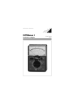
METRAmax 2
Analog multimeter
G
O
S
M SEN
ET
CA RA
M WA
ILL T
E T
BA
UE
R
Operating instructions
3-348-734-02
3/3.97
2
GOSSEN-METRAWATT
Contents
Page
1
Safety features and safety precautions .................... 4
2
Description ................................................................ 5
3
Operation ................................................................... 6
3.1 Operating controls .............................................................. 6
3.2 Getting started .................................................................... 6
3.2.1 Connecting the battery .......................................................... 6
3.2.2 Checking the mechanical zero ............................................... 7
3.2.3 Checking the electrical zero ................................................... 7
3.2.4 Battery test ........................................................................... 7
3.3 Voltage measurement ......................................................... 8
3.3.1 DC voltage measurement ...................................................... 8
3.3.2 Direct AC voltage measurement up to 300 V .......................... 8
3.3.3 AC voltage measurement with superimposed
DC voltage component .......................................................... 9
3.4 Current measurement ....................................................... 10
3.4.1 Direct DC current measurement ........................................... 10
3.4.2 DC current measurement via shunts .................................... 10
3.4.3 AC current measurement .................................................... 11
3.5 End of measurement ........................................................ 11
4
Specifications .......................................................... 12
5
Maintenance ........................................................... 14
5.1
5.2
5.3
Battery replacement ......................................................... 14
Fuse replacement ............................................................. 14
Cleaning ............................................................................ 14
6
Repair and replacement parts service .................... 15
GOSSEN-METRAWATT
3
1
Safety features and safety precautions
The analog multimeter METRAmax 2 is constructed in compliance
with the safety rules of IEC 1010-1/EN 61010-1/VDE 0411-1.
When properly used, the safety of both the user and the meter is
assured. Their safety is not assured, however, if the meter is misused or carelessly handled. That is why it is absolutely necessary
to carefully and completely read these operating instructions before
using the METRAmax 2 and to follow them in all respects.
Please note the following safety precautions:
• The meter must only be operated by persones who understand the danger of shock hazards and know how to apply safety precautions.
• Shock hazards exist wherever voltages of more than 30 V (RMS value)
to ground can appear.
• It must be taken into account that unexpected voltages can appear on
devices under test (e.g. defective devices).
Capacitors may be charged dangerously, for instance!
• Case and test leads must be in good condition, e.g. no cracks or broken
spots.
• The METRAmax 2 must not be used for measurements on circuits with
corona discharge (high voltage!).
• Be particularly careful when measuring on HF circuits.
Dangerous composite voltages may exist there.
• Measurements under moist environmental conditions are not permitted. Hands, shoes, floor and working site must be dry.
• Absolutely verify that overloading of the measuring ranges does not
exceed the permissible limits.
4
GOSSEN-METRAWATT
2
Description
On the METRAmax 2, the measuring ranges are selected with a
sliding function switch and a rotary range selector switch. The scale
is mirror-backed.
The rugged plastic case and the spring-loaded jewel bearings of
the stray-field-insensitive moving-coil movement with core magnet
protect the meter against damages in the case of severe mechanical stress.
The electrical zero of the pointer can be positioned at mid-scale.
This allows for bipolar DC voltage and DC current measurements
regardless of the polarity.
The connection sockets are protected against accidental contact.
Both the special test leads with contact-protected connection
plugs and all test leads with commercial banana plugs (4 mm diameter) can be used.
The DC current measuring ranges can be expanded by means of a
shunt (e.g. 10 A/100 mV).
The meter is of service-friendly design.
GOSSEN-METRAWATT
5
3
Operation
3.1
Operating controls
6
7
5
+
~
9V
6F22
2
1
4
3
1
2
3
4
5
6
7
Adjustment screw for the mechanical zero (
OFF on scale)
Sliding function switch
Rotary range selector switch
Rotary knob for mid-scale setting of the electrical zero
Safety connection sockets
Nose to open the meter
Battery compartment
3.2
Getting started
3.2.1 Connecting the battery
The battery compartment 7 contains a 9-V battery (IEC 6F22)
which is not connected. To connect the battery, it is required to remove the lower part of the case. For this purpose, press the nose
6 on the front of the meter inwards, using an adequate tool. Securely connect the battery contacts to the battery clip located in the
battery compartment. Ensure reliable contact making. Replace the
lower part of the case and press the two parts together until they
engage.
6
GOSSEN-METRAWATT
Caution!
Both test leads must be disconnected from the measuring circuit before opening the meter!
☞
Note
Automatic battery switch-off after 45 min. Switching off
and on again of the sliding function switch activates the
power supply.
3.2.2 Checking the mechanical zero
The METRAmax 2 must not be connected when checking the mechanical zero.
• Set the sliding function switch 2 to the "0" position
• Place the METRAmax 2 in a horizontal position
• The pointer must be located exactly above the line marked "
OFF"
• Correct the deviation by means of the adjustment screw 1 on
the bottom of the case using a screwdriver, if required
3.2.3 Checking the electrical zero
• Set the sliding function switch 2 to the
position, select the
measuring range
• The pointer must rest exactly above the line for the zero at midscale
• Correct deviations by means of the rotary knob 4, if required
3.2.4 Battery test
• Set the sliding function switch 2 to the "
" position
• Set the rotary range selector switch 3 to the "
" position
• The pointer must travel into the battery test section marked "
"
If the pointer no longer travels into the battery test section, or if
there is an instable indication, the battery is exhausted. It must be
replaced with a new one (see section 5 Maintenance, battery replacement).
GOSSEN-METRAWATT
7
3.3
Voltage measurement
3.3.1 DC voltage measurement
Operating mode: Electrical zero at left
+
• Set the sliding function switch 2 to the
position
• Set the rotary range selector switch 3 to the corresponding
measuring range: V 300 V ... 100 mV
• Connect the METRAmax 2
• Read the measured value: black scale
Operating mode: Electrical zero at mid-scale
• Set the sliding function switch 2 to the
position
• Set the rotary range selector switch 3 to the corresponding
measuring range: V 300 V ... 100 mV
• Check that the pointer rests at mid-scale, see section 3.2.3 on
page 7
• Connect the METRAmax 2
• Read the measured value: red scale +/–
3.3.2 Direct AC voltage measurement up to 300 V
• Set the sliding function switch 2 to the
position
• Set the rotary range selector switch 3 to the corresponding
measuring range: V 300 V ... 3 V
8
GOSSEN-METRAWATT
• Connect the METRAmax 2
• Read the measured value: black scale
To keep the influence of the frequency as low as possible, the connection socket " " should be connected to the ground potential
as directly as possible or to lowest point with respect to ground.
3.3.3 AC voltage measurement with superimposed
DC voltage component
The DC voltage component, such as occurs with an amplifier output stage, for example, can be cut off by means of a capacitor (recommended value: 4.7 µF/630 V). In this case, the additional service
error is smaller than 0.2% at a measuring frequency of 50 Hz. The
measuring procedure corresponds to the one described above.
The DC component can be determined same as with DC voltage
measurement.
To protect the meter against overload, the selected measuring
range must always be higher than the DC voltage component determined at first.
Caution!
Both voltage components must be tested before switching to a lower measuring range.
GOSSEN-METRAWATT
9
3.4
Current measurement
For all current measurements, connect the METRAmax 2 in series
with the consumer in the line having the lower potential to ground.
3.4.1 Direct DC current measurement
Operating mode: Electrical zero at left
+
• Set the sliding function switch 2 to the
position
• Set the rotary range selector switch 3 to the corresponding
measuring range: A 3 A...100 µA
• Connect the METRAmax 2
• Read the measured value: black scale
Operating mode: Electrical zero at mid-scale
• Set the sliding function switch 2 to the
position
• Set the rotary range selector switch 3 to the corresponding
measuring range: A 3 A...100 µA
• Check that the pointer rests at mid-scale, see section 3.2.3 on
page 7
• Connect the METRAmax 2 according to the wiring diagram
• Read the measured value: red scale +/–
3.4.2 DC current measurement via shunts
The accuracy of the measurement is influenced by the measuring
error of the shunt.
Operating mode: Electrical zero at left
+
10
GOSSEN-METRAWATT
• Set the sliding function switch 2 to the
position
• Set the rotary range selector switch 3 to the following position:
V 100 V
• Connect the METRAmax 2
• Read the measured value: back scale
Operating mode: Electrical zero at mid-scale
• Set the sliding function switch 2 to the
position
• Set the rotary range selector switch 3 to the following position:
V 100 mV
• Check that the pointer rests at mid-scale, see section 3.2.3 on
page 7
• Connect the METRAmax 2
• Read the measured value: red scale +/–
3.4.3 AC current measurement
• Set the sliding function switch 2 to the
position
• Set the rotary range selector switch 3 to the corresponding
measuring range: A 3 A...100 µA
• Connect the METRAmax 2
• Read the measured value: black scale
3.5
End of measurement
When no measurements are made, the sliding function switch 2
should always be set to "0" to conserve the battery life.
GOSSEN-METRAWATT
11
4
Specifications
Measuring ranges
DC and AC
voltage
100 mV
300 mV
1 V
3V
10 V
30 V
100 V
300 V
/
/
/
/
/
Internal resistance
10 MΩ
10 MΩ
10 MΩ
10 MΩ
10 MΩ
10 MΩ
10 MΩ
10 MΩ
1 MΩ
1 MΩ
1 MΩ
1 MΩ
1 MΩ
DC and AC
voltage
100 µA /
1 mA /
10 mA /
100 mA /
1 A /
3 A /
Voltage
drop
55 mV
55 mV
55 mV
55 mV
53 mV
51 mV
Infuence quantities and nominal ranges of use
Temperature
on the range 0 ... +40 ºC
Frequency
for all measuring ranges
± 2%/10 K on
± 2.5 % on the 30 Hz...1.5 kHz range
± 5 % on the 1.5 kHz ... 3 kHz range
Accuracy
Under reference conditions Class 2 for
Class 3 for
Reference conditions
Ambient temperature
Position of use
Frequency
Waveform
12
+23 ºC ± 2 K
Horizontal
50 ... 60 Hz
Sinusoidal
GOSSEN-METRAWATT
Power supply
Battery
Overload protection
9-V flat cell battery, IEC 6F22,
automatic battery switch-off
after 45 min.
Fuse F3,15 H/250 V acc. to
DIN VDE 0820 part 22/EN 60127-2
protects the circuits against overload. The movement is protected by
2 diodes in inverse-parallel connection.
Electrical safety
Protection class
Overvoltage category
Nominal voltage
Pollution degree
Test voltage
II acc. to IEC 1010-1/EN 61010-1/
VDE 0411-1
CAT III
300 V
2
3,7 kV∼
EMC
Emission
Immunity
Electromagnetic compatibility
EN 50081-1: 1992
EN 50082-1: 1992
Mecanical configuration
Dimensions
Weight
GOSSEN-METRAWATT
100 mm x 140 mm x 35 mm
approx. 300 g with battery
13
5
Maintenance
5.1
Battery replacement
When a battery test reveals that the pointer no longer travels into
the battery test section marked "
", the battery must be replaced. Replace the exhausted battery with a new 9-V flat cell battery according to IEC 6F 22. Remove the lower part of the case as
described in section 3.2.1 on page 6.
5.2
Fuse replacement
Remove the case as described in section 3.2.1 on page 6. The fuse
holders are soldered to the circuit board.
5.3
Cleaning
The meter must only be cleaned with a soft cloth or brush. Eventually existing static charges of the window can be eliminated by
means of an antistatic agent or a moist cloth.
14
GOSSEN-METRAWATT
6
Repair and replacement parts service
When you need service, please contact:
GOSSEN-METRAWATT GMBH
Service
Thomas-Mann-Straße 16 - 20
D - 90471 Nürnberg
Telefon (09 11) 86 02 - 4 10 / 4 11
Telefax (09 11) 86 02 - 2 53
This address if for Germany only. Abroad, our representatives or
establishments are at your disposal.
GOSSEN-METRAWATT
15
Printed in Slovenia ⋅ Subject to change without notice
G
O
S
M SEN
ET
CA R A
M WA
ILL T
E T
BA
UE
Company address:
Thomas-Mann-Straße 16 – 20
D – 90471 Nürnberg
Telefon (09 11) 86 02 – 0
Telefax (09 11) 86 02 – 6 69
R
GOSSEN-METRAWATT GMBH
D – 90327 Nürnberg