1
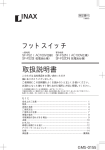
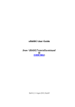
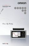
ELECTRO N IC D EVICES IN C.
P.O . BO X 15037, CHESAPEAKE, VA 23328. PH 757-421-2968 FAX 421-0518
LCS-300 User's Manual
V1.20
10/08/11
1 Overview
The LCS-300 is a LORAN C signal generator capable of simulating a LORAN chain with a
master and two slave stations. The signal characteristics are controlled from any ASCII
terminal via the RS-232 link.
The GRI, slave TD's, and amplitude of the pulse groups can be set. These settings can be
stored in eeprom to be recalled on power-up.
2 Setup
To prepare the LCS-300 for operation you must connect the power supply and a terminal
operating at 9600 baud, 8 bits, no parity and no handshake.
2.1
Power Supply
Any power supply providing 9 VDC at 200 mA can be used to power the LCS-300. The
plug is a standard 2.5mm power connector with the center pin positive. The input voltage
must be between 7 and 15 VDC.
2.2
Terminal
Microsoft HyperTerm, the supplied LCS-300_terminal.exe, or any terminal program
supporting RS232 can be used. Set the parameters to 9600,8,N,1 with no handshake and
connect the terminal to the DB9 connector on the rear panel using a standard 9-pin serial
cable. Note that the LCS-300_terminal.exe is configured with the correct baud rate for the
LCS-300.
2.3
Preliminary Test
Send 'enter' (0x0D) to clear the buffer in the LCS-300, then send a lower case 'i'. Do this
by typing 'i' followed by enter. The current settings for the GRI, TD's, and amplitudes will
be listed on the terminal screen.
2.4
LORAN Connection
Connect a LORAN receiver to the connector on the lower left of the front panel labeled
“Composite Loran C Output.” The LCS-300 can be connected directly to the LORAN
receiver or through the LORAN receiver's antenna coupler. Read the next section to learn
how to set the GRI, etc. to the required values.
3 Controlling the LCS-300
3.1
Command Structure
Commands are one or two letters followed by a numeric value. No spaces are used. All
commands must be followed by the 'enter' key. For instance, to set TD1 to a delay of
27.1234 uSec, type 'x271234' followed by the 'enter' key. Commands are case sensitive,
an uppercase 'X' will set the amplitude for TD1 not the delay.
3.2
Command List
?' or '/' prints a help file of commands to the terminal.
'D' saves current GRI, TD, ECD, amplitude and slew data to eeprom. The stored
values will be recalled on power-up.
3.2.3
'd' Recalls stored data from eeprom.
3.2.4
'e'n sets negative ECD in uS. 0 to -10 uS. Shifts the envelope to the left.
3.2.5
E'n sets positive ECD in uS. 0 to +10 uS. Shifts the envelope to the right.
3.2.6
'i' prints out all output data.
3.2.7
'l'nnn sets amplitude for TD1, TD2, and master to input.
3.2.8
'L'n sets additional 10 dB attenuator. 1 = no atten, 0 = -10dB atten.
3.2.9
'm'nnnn sets the GRI, 7980, 9960. etc.
3.2.10
'M'nnn sets the master amplitude, 0-255.
3.2.11
'q'n. If n = 1, sets quiet mode where only CSV numerical data is sent to terminal.
3.2.12
'sx'nnn sets TD1 slew rate. 1 is fastest, 255 slowest slew.
3.2.13
'sy'n sets TD1 slew rate.
3.2.14
sX'n sets TD1 slew direction. 0 = decrement, 1 = increment.
3.2.15
'sY'n sets TD2 slew direction.
3.2.16
'S'n Starts or stops the TD slew. 0 = no slew, 1 = slew TD's.
3.2.17
't'n sets Trig Out for master, TD1, or TD2. 0= master, 1= TD1, 2 = TD2.
3.2.18
'v' prints out the software version loaded in the LCS-300.
3.2.19
'x'nnnnnn sets the TD1 in tenths of a uS, 245678 = 24567.8 uS.
3.2.20
'X'nnn sets TD1 amplitude, 0-255.
3.2.21
'y'nnnnnn sets TD2 TD in tenths of a uS.
3.2.22
'Y'nnn sets TD2 amplitude, 0-255.
3.2.1
3.2.2
3.3
3.3.1
3.3.2
3.3.3
3.3.4
3.3.5
3.3.6
3.4
3.4.1
3.4.2
Basic Command Examples
Set the time delay for TD1 to 27208.5 uS.: 'x272085'
Set time delay for TD2 to 41100.4 uS.: 'y411004'
Set master pulse group amplitude to 150: 'M150'
Set TD1 pulse group amplitude to 97: 'X97'
Set the ECD to +3 uS.: 'E3'
Set the ECD to -2 uS.: 'e2'
Advanced Command Examples
Set TD2 slew rate to decrement the delay by 25 nS every 10th GRI: Type 'sx10'
to set rate, then 'sX0' to set slew direction to decrement. To start the slewing the
TD's, type 'S1. Remember to press the 'enter' key after each command. Slew
data for TD1 may be entered if required.
Set the trigger at Trig Out connector to coincide with TD2: Type 't2'. Signal at
the Trig Out connector will be a positive pulse that occurs 13.6 uSec before the
start of the TD2 pulse group.
4 Software Updates
4.1
The LCS-300 software can be updated via your RS-232 connection. As software
features are added, periodic update files in hex format may be sent via email. They
can be installed in the LCS-300 by using the supplied program, “proglcs.exe”.
4.1.1
Put the proglcs.exe program and the updated LCS300.hex file in the same
directory. The illustrations assume the program and hex file are in the c:\
4.1.2
Go to “Start – run” and type in the following: “c:\proglcs.exe -i COMx
Loran.hex”, where x is the connected com port number.
4.1.3
4.1.4
4.1.5
Press the reset (RST) button on the LCS-300 and click OK on the Run window.
Note that after a RST, status led 2 stays on 5 seconds, then goes off. You must
start the update while status led 2 is on for it to work successfully.
If the update is running successfully, you will see the following screen:
After the update, turn the LCS-300 power off for a second then back on before
using it. You may verify the software version by typing a 'v' then pressing 'enter'.
The software version will be displayed on the terminal.
5 Front Panel Outputs
The front panel has 6 outputs as shown below:
5.1
5.2
5.3
5.4
5.5
5.6
The Grp Trig output is a 5V positive going trigger occurring 13.6 uS before the start
of the master pulse group. It will have the same period as the GRI rate.
The Master output provides the 9 pulses of the master group. The unloaded
amplitude is 2.3 Vp-p and the source impedance is approximately 600 ohms.
The Slave1 output provides the 8 pulses of the first slave, or TD1, group. The
unloaded amplitude is 2.3 Vp-p when loaded and the source impedance is
approximately 600 ohms.
The Slave2 output provides the 8 pulses of the second slave or TD2group. The
unloaded amplitude is 2.3 Vp-p when loaded and the source impedance is
approximately 600 ohms.
The Option output is for future expansion.
The Composite Loran C output has the master and both slave groups present. The
unloaded amplitude for each pulse group can be set from 50 uV p-p to 1 Vp-p in
steps of 0.3dB. The source impedance is approximately 600 ohms. This output is
AC coupled and the maximum DC voltage level at this connector must be less than
40 volts. This is the output normally used when testing a Loran receiver and may be
directly connected to the Loran or through the coupler. If connecting to the high
impedance input of an antenna coupler, use a series capacitor of 47 pF from the
Composite Loran C output to the coupler's antenna terminal for best performance.
6 Back Panel Connections
The back panel has three status indicators, connections for RS-232 and power, and a trigger
output.
6.1
The PWR connector is a 2.5mm DC power input. Use the supplied wall transformer
or any linear power supply that will provide 9 VDC at 250 mA can be used to power
the LCS-300. The input voltage must be between 7 and 16 VDC. Fusing is
internal and auto-resets. Note that sustained voltages over 16 VDC may damage the
internal power supply. Switching power supplies may generate noise in the Loran
frequency band and are not recommended for low signal level testing.
6.2
The RS-232 connector is a standard DB9 socket. The baud rate is preset to 9600,
no parity, with 8 bits of data, and 1 stop bit. Only three wires - ground, Tx data,
and Rx data - are used. There is no handshaking. Note that the RS-232 port is not
galvanically isolated from the LCS300. For minimum noise, an external optoisolator should be used.
6.3
Status indicators
6.3.1
Status 1 is the power indicator and will illuminate whenever the LCS-300 is
connected to a power source.
6.3.2
Status 2 indicates that the LCS-300 is in the boot-loader mode and ready to
receive a program update. It lights up for 5 seconds after power is applied.
6.3.3
Status 3 blinks during data transmission.
6.4
The Trig Out connector has selectable trigger points. Trigger pulses may be
selected for the master, slave1, or slave2 pulse group. The trigger pulse begins 13.6
uS before the start of the selected pulse group.
6.5
The RST button resets the LCS-300 to power-up condition and the default
parameters will be loaded. This is normally used to reset the unit when updating the
software via the LCS-300's boot-loader.
7 GRI and TD Limits
7.1
The slave time differences must be chosen so that slave1 group starts after the
master group has finished transmitting. Slave2 pulse group must not start before
slave1 has finished transmitting. The slave groups are composed of 8 pulses spaced
1 mS apart and have a total length of 8.5mS. The Master has a length of 10.5 mS.
7.1.1
Slave 1 > 10.5 mS.
7.1.2
Slave 2 > slave 1 + 8.5 mS.
7.1.3
Slave 2 < GRI – 8.5mS.
7.2
It is the users responsibility to make sure the TD values are realizable; no error
checking is performed on the input data to the LCS-300. If the slaves are allowed to
overlap each other or the master, the loran receiver may not track properly.
8 Specifications
8.1
Power supply requirements are 9VDC at 250 mA maximum.
8.2
Internal time base: 10 MHz TCXO, 1 ppm over temperature of -10 to +60
degrees centigrade, aging < 1 ppm/year.
8.3
Composite Loran Output level range is 0 to -86.5 dB referred to 1 volt p-p maximum
output for each pulse group. Resolution is 0.3 dB/step and the accuracy is +/- 1.5 dB
over the 86.5 dB range.
8.3.1
All outputs except for the Group trigger are 600 ohms and can tolerate DC
voltages of +/- 20V. The Group trigger output is 0-5V with 1K impedance.
Voltage must not be applied to this output or damage may occur.
8.4
GRI range is 33mS to 500mS, resolution is 100uS.
8.5
Slave1 TD range limit is 11000uS minimum to GRI - 11000uS maximum.
Resolution is 100 nS.
8.6
Slave2 TD range limit is Slave1 TD + 11000 uS to GRI - 11000uS maximum.
Resolution is 100 nS.
8.7
ECD range is +10 to -10 uS in 1 uS steps.
8.8
Baud rate is 9600, 8 bits, no handshake, 1 stop bit.
8.9
Size of LCS-300: 15.9cm wide x 8.3cm high x 17cm deep, including connectors.
8.10
Shipping weight is 2 Kg.
9 Warranty Information
Unit will be repaired free of charge for one year from date of purchase providing there is no
water damage or other evidence of improper use or handling. Purchaser must ship unit
prepaid to address below. EDI will pay the return freight.
Electronic Devices Inc.
3140 Bunch Walnuts Rd.
Chesapeake, VA 23322
USA
Phone: 757-421-2968
Fax: 757-421-0518
www.dsts.com