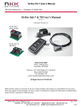
1
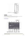
Autoline VX10
Roadmarking Controller System
Rev 1.0
Autoline VX10 User Manual
1
Table of Contents
Hardware Tour
3
Main Operation
5
Operation Description
5
Idle Mode Operation
5
Menu Operation
8
Marking Mode Operation
10
Smartswitch
11
Autoline VX10 User Manual
2
Hardware Tour
VX10 Vehicle-Mount PC:
Power Indicator LED:
Green LED is ON if power is applied to VX10 Vehicle-Mount PC.
Brightness Control Keys:
These keys turn the brightness of the screen UP and DOWN.
During day operation the brightness is best set to a high-brightness.
During night operation the brightness is best set to a low-brightness.
USB Port:
USB memory stick can be connected for software updates and data downloads. There are also 2 x
USB ports along the bottom I/O panel.
USB download of work will be available as an optional add-on. This will be available with the Q3-2011
software update.
Touchscreen:
The display is a touchscreen, and provides intuitive menu navigation and operation. Active key areas
can be simply touched.
Function Keys:
There are five illuminated function keys along the bottom (F1:F5). These can be used instead of the
touchscreen. The banner along the bottom of the screen will display the function of each key.
Autoline VX10 User Manual
3
Power Button:
Press power button to turn VX10 ON.
The VX10 can be shut down by also pressing the power button, this takes a few seconds to occur.
However, the preferred method of shut down is via the menu command.
LX10 Controller:
Autoline VX10 User Manual
4
Main Operation
Operation Description:
There are two main modes of operation – Idle Mode and Marking Mode. The modes can be identified
by the STOP / START key on the function banner.
Idle Mode:
Idle Mode is where the functions that are carried out with the vehicle stationary are performed. These
include setup, calibration, clearing counters, selecting jobs, software updates, downloading data etc.
Idle Mode is identified by the display of ‘START’ in the bottom-right corner of the screen.
Marking Mode:
Marking Mode is where the tasks that are associated with marking are performed. These include
enabling and disabling paint and bead power, selecting patterns, and marking patterns etc.
Marking Mode is identified by the display of ‘STOP’ in the bottom-right corner of the screen.
Press START key to enter Marking Mode.
Press STOP key to revert to Idle Mode.
Idle Mode Operation:
Display Modes:
There are three display modes that can be selected. The display mode can be changed in Idle Mode or
Marking Mode.
Press the ‘Display Mode’ key to change display mode.
Basic Display Mode:
•
•
•
•
•
Large-Sized Thickness and Speed Gauges
Selected Pattern Descriptions
Job Title
Status for Paint Guns / Bead Guns / Latch Mode [ON/OFF]
Totaliser Counters
Standard Display Mode:
•
•
•
•
•
•
Medium-Sized Thickness and Speed Gauges
Selected Pattern Descriptions
Metre/Litre Counters
Job Title
Status for Paint Guns / Bead Guns / Latch Mode [ON/OFF]
Totaliser Counters
Autoline VX10 User Manual
5
Detailed Display Mode:
•
•
•
•
•
•
•
•
Selected Pattern Descriptions
Metre/Litre Counters
Counter for Applied Distance (lines only, not gaps)
Reading for Average Thickness (calculated over entire pattern distance)
Trigger / Output Details
Job Title
Status for Paint Guns / Bead Guns / Latch Mode [ON/OFF]
Totaliser Counters
Basic Display Mode
Standard Display Mode
Autoline VX10 User Manual
6
Detailed Display Mode
Job Select:
This key will enter the Job Select page where the required Job can be opened. All marking data will be
recorded to this Job when Marking Mode is entered. The current job title is displayed in the top-left
corner of the display.
Job titles are listed only numerically for the software version V1.0. An upcoming software update will
allow text fields to be entered so meaningful job titles can exist (e.g. State Highway 16). Available with
the Q3-2011 software update.
Pattern Select:
This key will enter the Pattern Select page. When a pattern is selected in Idle Mode, operation will
automatically progress to Marking Mode.
Patterns can be viewed in either list format or graphical grid format.
Pattern Select View is set in Menu/General.
List Format
Autoline VX10 User Manual
Graphical Grid Format
7
Menu Operation:
The menu can only be accessed in Idle Mode.
Clear Counters:
Counters for patterns and totalisers can be cleared to zero. Counters include distance and paint used.
There are several options when clearing counters:
•
•
•
•
•
All counters for current pattern.
Counters for individual patterns.
All pattern counters for current job.
Total metres counter.
Total litres counter for each pump.
Select the desired option and then press ‘Clear”.
Standby:
Standby mode is useful when traveling from one job site to another where it is desirable to disable all
marking operation for safety reasons. This saves the operator having to completely shut down the VX10
Vehicle-Mount PC.
Standby mode turns off the peripheral power that powers the peripheral devices (e.g. Remote Readouts,
Smartswitches, Triggers, Sensors etc). The VX10 Vehicle-Mount PC screen is also turned off.
Enter Standby Mode by pressing Menu/Standby Mode.
Exit Standby Mode by pressing Standby Mode.
Setup:
This is where most system settings are configured.
General:
Line Adjust Units:
Pattern Select View:
Speed Display Accuracy:
Minimum Speed:
Speed Warning Range:
Thickness Warning Range:
Readout Backlight:
Can be set as either distance-based or time-based (see page 13).
Can be set as either list or graphical grid format (see page 10).
Sets number of decimal places of speed display.
Sets minimum speed that system will allow marking.
Disabled. Available with the Q3-2011 software update.
Disabled. Available with the Q3-2011 software update.
Sets the backlight level on the remote readouts.
Sensors:
Calibration procedures for speed and pump sensors are located in this sub-menu. Follow on-screen
prompts for detailed calibration instructions.
Triggers:
Line Break:
Trigger Offset Value:
Trigger Offset Enable:
Autoline VX10 User Manual
Sets the triggers that activate the Line Break function.
Sets the offset between when the trigger is activated and when the
output is activated.
Enables / Disables trigger offset function.
8
Outputs:
Distance Spot Length:
Timed Spot Length:
Fast Output Speed:
Output Offsets:
Output Types:
Sets length for distance-based spots.
Sets duration of time-based spots.
Sets speed threshold for fast/slow paint output operation.
Sets offsets between outputs to help match material placement on
road. Useful for the matched placement of paint and beads.
Sets the material type for each output.
Diagnostics:
The Diagnostics mode provides a method of testing sensors, triggers, and outputs.
About:
Displays software version details and licencing information.
Shut down:
This is the preferred method of shutting down the VX10 Vehicle-Mount PC, rather than using the Power
Button.
Autoline VX10 User Manual
9
Marking Mode Operation:
Pattern Select:
This key will enter the Pattern Select page.
Patterns can be viewed in either graphical format or list format.
Pattern Select View is set in Menu/General.
Line Adjust:
Line Adjust setting compensates for mechanical delays within the system by increasing / decreasing the
line length output slightly. The mechanical delays are be introduced by the air system, solenoids, and
guns etc.
The outputs used by the selected patterns are listed. Either all outputs can have the line adjust setting
edited globally, or outputs can be adjusted individually.
Line Adjust can be set as either a distance-based (mm) or time-based (ms) value. Time-based
adjustment gives an adjustment independent of the vehicle speed and is the preferred setting.
Distance-based adjustment is a legacy option that provides a constant adjustment based on speed
pulses.
Options:
PAINT OUTPUTS:
BEAD OUTPUTS:
LATCH MODE:
Disables / Enables outputs for paint.
Disables / Enables outputs for beads.
Disables / Enables the Latch Mode function.
The above options can be enabled / disabled using the touchscreen or function keys to toggle the
ON/OFF settings.
Press the Exit key when setting changes are complete.
Latch Mode:
Latch Mode latches ON the line outputs until the completion of the line pattern (if enabled in the pattern
program). This semi-automatic functionality is useful for remark work and multiple line (barrier)
applications.
During remark work the start of the line output can be triggered by momentarily activating the input
switch. The programmed line length will be outputted and stopped automatically at completion.
Multiple line (barrier) applications can be configured so multiple line outputs turn off together when
deactivated. This provides a uniform line finish which is required in some applications.
The Latch Mode function is ignored by patterns containing only solid lines. This is because these
patterns do not have a known end to the line.
Marking Operation:
Basic marking operation as follows:
1.
2.
3.
4.
Select pattern.
Set Paint Outputs / Bead Outputs / Latch Mode [ON/OFF] as required.
Drive vehicle at required application speed.
Activate trigger to start line outputs. Deactivate trigger to stop line outputs.
Press STOP key to disable marking immediately, and revert to Idle Mode.
Refer to the Smartswitch section for instructions regarding marking operation with the Smartswitch.
Autoline VX10 User Manual
10
Smartswitch
Introduction:
The Smartswitch device provides the following features:
•
•
•
•
•
•
Quick pattern selection.
Ability to change patterns without stopping.
Improves application of multiple line patterns (e.g. Barrier patterns).
Cycle Lock allows for “hands-free” operation.
Remote control of line adjustment settings.
Both RHS (SX10) / LHS (SX11) models available.
Operation:
General Mode Operation:
When the Smartswitch is powered up the current Mode is indicated by either the ‘Manual’ or ‘Latch
Mode’ LEDs being illuminated. This indication also acts as a Power ON indicator.
The Mode operation is global and synchronised with and the VX10 Mode setting. (i.e. Turning off Latch
Mode on Smartswitch also disables Latch Mode on VX10, and vice-versa).
Autoline VX10 User Manual
11
Manual Mode:
Select patterns by pressing the pattern buttons. The microswitch is then used to start / stop marking.
Pressing the microswitch will start the pattern outputs.
Releasing the microswitch will stop the pattern outputs.
•
•
No outputs will auto-start. No patterns will latch ON.
Pressing the STOP button will de-select the pattern and revert the VX10 to Idle Mode
(stopped).
Latch Mode:
Latch Mode latches ON the line outputs until the completion of the line pattern (if enabled in the pattern
program). This semi-automatic functionality is useful for remark work and multiple line (barrier)
applications.
The pattern is selected by pressing the required pattern button.
•
•
If the pattern is programmed with the auto-start feature set, then the line outputs will activate
automatically. Otherwise pressing the microswitch activates the line outputs.
Patterns with only solid line outputs (e.g. BB, Solid Edgeline) will be latched ON indefinitely in
Latch Mode. This indefinite latching only occurs when the pattern is activated using the
Smartswitch, standard trigger operation will not cause indefinite latching.
During remark work the start of the line output can be triggered by pressing and releasing the
microswitch. The programmed line length will be outputted and stopped automatically at
completion.
Pattern outputs can be deactivated by either pressing the STOP button, or pressing the MODE
button to revert to Manual Mode.
Pressing the STOP button whilst no patterns are active will de-select the pattern and revert the
VX10 to Idle Mode (stopped).
Changing Patterns In Latch Mode:
There are two methods of changing patterns in Latch Mode. These are instant pattern change and
queued pattern change. Both methods allow for pattern change without stopping.
Instant Pattern Change:
This method of pattern change is most useful during remark work where the pattern transition point can
be unpredictable.
To change pattern press the next pattern button WITHOUT the microswitch held down.
•
•
The current pattern stops immediately and the next pattern is selected and started.
If the pattern is programmed with the auto-start feature set, then the line outputs will activate
automatically. Otherwise pressing the microswitch activates the line outputs.
Queued Pattern Change:
This method of pattern change is most useful during new work where the pattern transition can be
predicted.
To change pattern press the next pattern button WITH the microswitch held down.
•
•
The current pattern will complete the last line or gap before changing to the next pattern.
During the transition period the next pattern’s LED will flash to indicate a pending pattern
change.
Autoline VX10 User Manual
12
Cycle Lock:
Cycle Lock allows for “hands-free” operation. This is advantageous during long distances of continuous
pattern application because the operator does not need to hold down the microswitch throughout
operation.
When in Latch Mode and a pattern is active, pressing the MODE button while the microswitch is
depressed will result in the Cycle Lock being enabled.
The Cycle Lock can be disabled by either pressing the STOP button, or pressing the MODE button to
revert to Latch Mode.
The Cycle Lock will remain enabled when patterns are changed.
Enable Cycle Lock:
Disable Cycle Lock:
Hold down microswitch and press MODE button.
Press STOP button, or press MODE button to revert to Latch Mode.
Line Adjustment Keys:
The Line Adjustment keys can be used to adjust the length of the lines remotely without having to
change the settings on the VX10 Vehicle-Mount PC.
The ‘-‘ key decreases the line length, while the ‘+’ key increases the line length.
This User Manual is intended for reference purposes only.
All manual content and product specifications are subject to change without notice.
No part of this publication may be reproduced in any form or by any means, electronic,
photocopying, recording or otherwise, without prior written permission of the publisher.
All brand and product names are trademarks or registered trademarks of their respective
companies.
© RMSD Ltd. 2011
Autoline VX10 User Manual
13