1
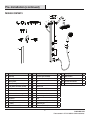
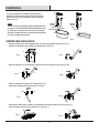
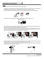
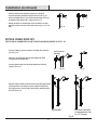
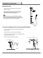
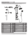
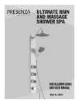
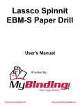
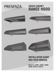
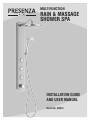
MULTIFUNCTION
RAIN & MASSAGE
SHOWER SPA
INSTALLATION GUIDE
AND USER MANUAL
Model No. QB018
Table of Contents
Table of Contents . . . . . . . . . . . . . . . . . . . . . . . . . . . . . 2
Safety Information. . . . . . . . . . . . . . . . . . . . . . . . . . . . . 2
Warranty
One Year Limited Warranty. . . . . . . . . . . . . . . . . . . . . . . . . . . . 3
Warranty Claim Procedure. . . . . . . . . . . . . . . . . . . . . . . . . . . . 3
Pre-Installation
Tools/Materials Required. . . . . . . . . . . . . . . . . . . . . . . . . . . . . 4
Package Contents . . . . . . . . . . . . . . . . . . . . . . . . . . . . . . . . . . 5
Installation
Shower Head Installation. . . . . . . . . . . . . . . . . . . . . . . . . . . . . 6
Double Sided Tape Method . . . . . . . . . . . . . . . . . . . . . . . . . . . 8
Bottom Bracket Method. . . . . . . . . . . . . . . . . . . . . . . . . . . . . . 9
Shower Stall/Uneven Surfaces . . . . . . . . . . . . . . . . . . . . . . . 10
Operation. . . . . . . . . . . . . . . . . . . . . . . . . . . . . . . . . . 11
Troubleshooting . . . . . . . . . . . . . . . . . . . . . . . . . . . . . 11
Maintenance . . . . . . . . . . . . . . . . . . . . . . . . . . . . . . . 11
Service Parts . . . . . . . . . . . . . . . . . . . . . . . . . . . . . . . 12
Safety Information
READ AND SAVE THESE INSTRUCTIONS
CAUTION: Always wear safety goggles and gloves during
installation to prevent personal injury.
1. Inspect your unit before proceeding. Once you unpack your unit,
check for chips, scratches, cracks, dents or scuff marks. If any
damage is noticed, do not install.
2. Use this unit only in the manner intended by the manufacturer. If
you have any questions, contact the manufacturer.
3. Installation work and plumbing must be done by qualified
person(s) in accordance with all applicable codes and standards.
4. Protect the entire surface during installation.
BEFORE YOU BEGIN
1. Installs on both flat and uneven surfaces of up to 1 1/2”
(38 mm), see Fig. 1.
2. This unit might not be suitable for installation with some
fiberglass or acrylic showers.
3. This product will connect with your current shower valve. There
is no need to take out your current valve or change it.
Flat mounting surface
Uneven mounting surface
Fig. 1
2
Warranty
ONE YEAR LIMITED WARRANTY
A thorough inspection must be made before installation and any damage must be promptly reported. We will not be liable for failures or damage that
could have been discovered or avoided by proper inspection and testing prior to installation.
Conglom Kitchen & Bath warrants this product to be free from defects in materials or workmanship for one (1) year from the date of purchase. Proof
of purchase (original sales receipt) from the original consumer purchaser must be made available to Conglom Kitchen & Bath for all warranty claims.
This warranty is non-transferable and shall be voided if the unit is removed from its initial installation or if it is not installed following the manufacturer’s
instructions. It does not apply in the event of product damage due to the use of other than genuine Conglom Kitchen & Bath replacement parts,
(Replacement parts may be obtained by e-mail at [email protected] or by calling 1-877-333-0098 between 8:30 am - 5:00 pm EST)
installation error, abuse, misuse or improper care and maintenance (whether performed by a plumber, contractor, service provider or member of
the purchaser’s household). The warranty excludes damage due to aggressive air or water conditions, harsh or abrasive cleaners and/or materials.
Under no circumstance shall we be held liable for personal injury or property damage resulting from improper installation or use of this product.
We will not be held liable for inconvenience caused by loss of use of this product, costs incurred for labour or materials, removal and installation
of replacement units, or any other incidental or consequential damages. Costs relating to obtaining access for repair or replacement are the
responsibility of the user.
Our obligation shall be limited to the repair or replacement of a unit (at our discretion) that may prove, by our sole examination, to be defective under
normal use and service during the warranty period.
Any failure of this product that is not traceable to a defect in material or workmanship is not covered by this warranty. These non-warrantable items
include, but are not limited to:
-- Improper installation not in accordance with manufacturer’s instructions.
-- Dents and/or scratches incurred during shipping, handling, or installation.
-- Change in colour or finish due to chemical usage.
-- Damage caused by failure to follow care and cleaning guidelines, including damage caused by the use of abrasive cleaners.
-- Alterations made to the unit by the purchaser or installer.
-- Damage caused by accidental impact, fire, flood, freezing, and normal wear.
-- Bends and warping caused by forced connections, over-tightened fittings, and inadequate support during installation.
This warranty does not extend to commercial and institutional installation or use.
WARRANTY CLAIM PROCEDURE
If a claimable defect occurs or replacement parts are needed, please contact our customer service team at [email protected] or
1-877-333-0098 (8:30 am - 5 pm, EST, Monday - Friday).
Before you make your call, please ensure that you have:
-- Model number or description.
-- Proof of sale.
-- Details regarding the defect and/or part number.
-- Name(s) and address(es) of the owner and installer.
3
CONGLOMKB.COM
Please contact 1-877-333-0098 for further assistance.
Pre-Installation
TOOLS/MATERIALS REQUIRED (NOT SUPPLIED)
Measuring tape
Carpenter’s square
Wrenches
Phillips screwdriver
Electric drill with
1/4 in. (7 mm) drill
bit
Pencil
Safety gloves
Safety goggles
4
Pre-Installation (continued)
PACKAGE CONTENTS
Q
P
E
B
A
C
D
E
F
M
T
U
N
L
R
G
V
H
J
K
S
W
Z
AA
CC
BB
1
X
U
DD
2
Y
N
Part Description
Qty
Part Description
Qty
Part Description
Qty
A
Allen key
1
P
Top cover (pre-installed)
1
AA Wall anchors
3
B
Teflon tape
1
Q
Stainless steel cover (pre-installed)
1
BB
Bottom bracket
1
C
Mesh gasket
1
R
Nut
1
CC
Screws and washers
3
D
Check valve (pre-installed)
1
S
Shower column
1
DD Aluminum plate cover
E
Long brass connector (55 mm)
1
T
Shower arm
1
F
Short brass connector (28 mm)
3
U
Rubber washer (1/2”)
2
G
Stainless steel washers
2
V
Shower head
1
H
Stainless steel mounting bracket
1
W
Handheld shower head
1
J
Nut
1
X
Check valve (pre-installed)
1
K
Restrictor
1
Y
Hose
1
L
L-Fitting
1
Z
Handheld bracket (pre-installed)
1
M
L-Fitting
1
1
Upper body jet
1
N
Rubber washer (1/2”)
2
2
Middle and bottom jet
2
5
2
CONGLOMKB.COM
Please contact 1-877-333-0098 for further assistance.
Installation
This unit is designed to be installed using your existing
plumbing. Your shower valve, diverter valve or diverter tub
spout will be used in its current position and will operate as
before, see Fig. 2.
NOTE:
This unit can either be installed with OPTION A: DOUBLE SIDED TAPE
(see page 8) or OPTION B: BOTTOM BRACKET AND SCREWS (see page
9). In both cases, the weight of the unit is carried by the mounting
bracket (H). The double sided tape or the bottom bracket (BB) prevent
the unit from swinging during operation.
Existing
shower
valve
Tub spout
Existing
shower
valve
Diverter
Diverter
Fig. 2
SHOWER HEAD INSTALLATION
-- Remove the top cover (P) and the stainless steel cover (Q) from the shower column (S), see Fig. 3.
-- Remove the nut (R) that is pre-installed in the shower arm (T), see Fig. 4.
Q
T
P
Fig. 3
Fig. 4
S
R
-- Insert the shower arm (T) into the shower column (S) and secure it with the nut (R), see Fig. 5 & 6.
T
Fig. 5
T
Fig. 6
R
S
-- Place the rubber washer (N) onto the L-fitting (M), see Fig. 7.
-- Connect the L-fitting (M) to the shower arm (T), see Fig. 8.
N
M
Fig. 8
Fig. 7
T
M
-- Check that the rubber washer (U) that is pre-assembled on the shower head (V) is not loose, see Fig. 9.
-- Screw the shower head (V) on to the shower arm (T), see Fig. 10.
U
ST
Fig. 9
Fig. 10
V
V
6
Installation (continued)
NOTE:
Make sure that your shower valve is closed at all times from now until the testing is required.
-- Disassemble your existing shower head (1). Pull away from the wall cover (2) that is in the area where the shower arm (3) meets the
wall. Mark clearly on your existing shower arm, the level at which the wall meets the shower arm, see Fig. 11.
-- Remove your existing shower arm (3) from the wall using a wrench and turning it counter-clockwise. DO NOT DISCARD YET.
3
3
2
3
Mark shower
arm here
1
Fig. 11
-- Put teflon tape (B) on the end of the long brass connector (E) that has the white check valve (D), see Fig. 12.
Teflon tape on this end
2 3/16” (55.6 mm)
B
E
D
Fig. 12
-- Put your old shower arm (the one you have just removed) on a flat surface. Beside it put the long brass connector (E) with the teflon
tape (B) and check valve (D) side aligned with the threaded side of the shower arm.
-- On the end of the long brass connector (E) (the end that has the hexagonal hole inside) add, as needed, the small brass connectors
(28 mm, 1 11/10”) (F) threading them in place, until the total length of the brass connector assembly is between 5/8” and 1 1/8” (16
mm and 29 mm) longer than the place where the mark was made on the shower arm.
F
Mark on shower arm
This distance
should be
between 5/8”
and 1 1/8”
E
Teflon side
Align here
This distance
should be
between 5/8”
and 1 1/8”
E
F E
F
This distance
should be
between 5/8”
and 1 1/8”
F
E
F F E
F
This distance
should be
between 5/8”
and 1 1/8”
F
F
E
F F F E
Fig. 13
-- Using the provided Allen key (A), install the new assembled brass connector, (see Fig. 14), making sure that the end where you placed
the teflon tape (where the check valve is) goes towards the wall where the old shower arm was.
-- Clean the wall around the brass connector assembly throroughly with a dry cloth. Peel the paper backing from the double sided tape
on the stainless steel mounting bracket (H), see Fig. 15.
A
Assembled brass
connector
Fig. 14
H
Fig. 15
Wall
7
CONGLOMKB.COM
Please contact 1-877-333-0098 for further assistance.
Installation (continued)
-- Place the stainless steel mounting bracket (H) on the brass
connector assembly and adhere upright to the wall, see Fig. 16.
H
-- Secure and tighten the nut (J) on brass assembly using one or 2 of
the stainless steel washers (G), if required, see Fig. 17.
-- Bracket (H) allows for mounting this unit on flat walls or on walls
that have a shower surround or tiles with a step of up to 1 1/2” (38
mm).
G
J
Fig. 17
Fig. 16
OPTION A: DOUBLE SIDED TAPE
FOR FLAT WALLS, SHOWER STALLS, AND TILES WITH AN UNEVEN SURFACE OF UP TO 1 1/2”
-- Connect L-fitting (L) to brass connector assembly using restrictor
(K), see Fig. 18.
Brass Connector
Assembly
K L
-- With a dry rag, thoroughly clean the wall between the brass
connector and the shower valve.
H
-- Peel the paper backing from the double sided tape on back of
column, see Fig. 19.
Fig. 19
Fig. 18
-- Hang the shower column (S) on the stainless steel mounting bracket
(H) through holes in the column. Position column vertically level,
then apply pressure to main body to firmly adhere mounting tape to
the wall, see Fig. 20.
H
H
S
S
With flat wall
Fig. 20
8
With stalls or tiles with
an uneven surface of up
to 1 1/2” (38 mm)
Installation (continued)
OPTION B: BOTTOM BRACKET AND SCREWS
FOR FLAT WALLS ONLY
inlet
-- Insert wall anchors (AA) in pre-drilled holes. Secure bottom bracket
(BB) to the wall with screws and stainless steel washers (CC), see
Fig. 22.
22 1/4” (56.5 cm)
-- Mark the drill holes 1/4” (0.635 cm) (see Fig. 21). The three holes
consist of two holes drilled side by side, 0.67” (1.7 cm) apart from
the center of each hole with the center line running between them.
The third hole is drilled on the center line 0.79” (2 cm) below the
first two holes. The upper two holes should be drilled below the
shower pipe, 22 1/4” (56.5 cm) from the center of the top two holes
to the center of the inlet pipe.
0.67” (1.7 cm)
0.79” (2 cm)
Fig. 21
-- Connect L-fitting (L) to brass connector assembly using restrictor
(K), see Fig. 23.
22 1/4” (56.5 cm)
inlet
-- Hang the bottom of the shower column (S) on the bottom bracket
(BB) first, then hand the shower column (S) on the stainless steel
mounting bracket (H) through the holes in the shower column, see
Fig. 24.
0.67” (1.7 cm)
0.79” (2 cm)
AA BB
CC
Fig. 22
H
K
L
S
H
S
BB
Fig. 23
Fig. 24
9
CONGLOMKB.COM
Please contact 1-877-333-0098 for further assistance.
Installation (continued)
FINAL INSTALLATION
Q
P
-- Replace top cover (P) and the stainless cover (Q) on the shower
column (S), see Fig. 25.
-- Attach long flexible shower hose (Y) to the column body (S) and
handheld shower head (W) with rubber washers (N), (U). Check
valve (X) comes pre-installed in handheld shower.
S
NOTE:
Make sure that none of the hoses are bent or kinked after final installation.
Check water connections for proper flow; make sure there are no leaks. Do not
forget to use the rubber washers to prevent leaks on the connections. If you find
that the water pressure or volume is low, clean the mesh gasket (C).
W
U
N
Y
Fig. 25
IF YOU HAVE A SHOWER STALL OR TILES WITH AN ENEVEN SURFACE
-- Measure the length of the gap between the top of the shower panel and
the stall, see Fig. 26.
-- Cut both aluminum covers (DD) with scissors to desired length.
-- Remove the paper backing from the aluminum covers (DD) then stick them
on the gap from the panel to the wall.
-- Stick the aluminum covers (DD) in place, see Fig. 27.
Distance
DD
DD
Distance
DD
Fig. 26
Fig. 27
10
Operation
To use the shower panel, open your shower valve (as per normal use) and flip
the diverter valve on the shower valve or on the tub spout to redirect water
from the toe tester or tub’s spout to the shower.
Use the selector switch (Fig. 28-30) to choose between the three single use
options:
1
Selector
switch
2
Selector
switch
Fig. 28
Fig. 29
Selector
switch
Selector
switch
1. Shower head
2. Body jets
3. Handheld shower
4
You can also choose three combined use options by placing the selector in
between the icons (Fig. 31-33):
3
Fig. 30
4. The shower head and the handheld COMBINED
Fig. 31
5. The handheld shower and the body jets COMBINED
6. The body jets and the shower head COMBINED
Adjust water temperature and pressure using your existing shower valve.
6
Selector
switch
5
Fig. 32
Selector
switch
Fig. 33
Troubleshooting
-- Make sure that the rubber washers (N), (U) are properly installed to prevent leaks.
-- Make sure that you drill holes according to the instructions and that you secure the shower column (S) with the double-sided tape or on
the bottom bracket.
-- If you find that water pressure or volume is low, clean the mesh gasket (C).
-- If there is no water flow, check the brass connector (E) to make sure that it has not been installed incorrectly. Refer to Fig. 12 & 13 (on
page 7) of the installation guide.
-- If the check valve (D) is installed correctly and there is still no water flow, take the shower column (S) off the wall, loosen the L-fitting
(L) and check that the restrictor (K) is not blocked by debris. Take the restrictor off, clean with water and reinstall.
Maintenance
-- After use, rinse the shower column with water using the handheld shower to remove any soap deposits. Should water spots occur,
clean with a mild solution of vinegar and water followed by a thorough rinse.
-- Use liquid soap, a general household cleaner, or a weak solution of vinegar and water for regular cleaning.
-- Never use abrasive cleaners as they will scratch the finish.
11
CONGLOMKB.COM
Please contact 1-877-333-0098 for further assistance.
Replacement Parts
If you are missing parts or if you require replacement parts, please contact our customer service team at [email protected] or
1-877-333-0098, 8:30 am - 5 pm, EST Monday - Friday. Identify the required part(s) and have the part number(s) ready.
Q
P
T
U
N
E
C
E
F
R
G
V
H
J
K
W
Z
AA
BB
CC
1
U
DD
2
Y
N
Part Description
Code
Qty
Part Description
Code
Qty
C
Mesh gasket
QHB117
1
U
Rubber washer (1/2”)
QHB105
2
E
Long brass connector (55 mm)
QHB114
1
V
Shower head
QHB107
1
F
Short brass connector (28 mm)
QHB118
3
W
Handheld shower head
QHB111
1
G
Stainless steel washers
QHB101
2
Y
Hose
QHB106
1
H
Stainless steel mounting bracket
QHB115
1
Z
Handheld bracket
QHB112
1
J
Nut
QHB119
1
1
Upper body jet
QHB124
1
K
Restrictor
QHB120
1
2
Middle and bottom jet
QHB125
2
N
Rubber washer (1/2”)
QHB104
2
AA Wall anchors
QHB102
3
P
Top cover
QHB121
1
BB Bottom bracket
QHB103
1
Q
Stainless steel cover
QHB122
1
CC
QHB100
3
R
Nut
QHB123
1
DD Aluminum plate cover
QHB116
2
T
Shower arm
QHB126
1
12
Screws and washers
Imported by:
St-Laurent, Québec, H4S 2C3
1-877-333-0098
www.conglomkb.com
Made in China
Retain this manual for future use.