1
Database Products
DPS 7000
Administrator's Manual
SQL7 Administrator's Guide
GCOS 7
Software
Subject:
This manual describes the administrative tasks associated with the
SQL7 product
Special Instructions:
This manual supersedes revision 0 and revision 1 for all users of
GCOS 7 release V7.
Software supported:
GCOS 7 AP/HPS/EXMS Release V7
SQL7 V3x
Date:
January 1997
Bull Electronics Angers S.A.
CEDOC
Atelier de reprographie
331, Avenue Patton
49004 ANGERS Cedex 01
FRANCE
47 A2 51UR Rev02
Bull HN Information Systems Inc.
Publication Order Entry
FAX: (508) 294-7411
MA02/423S
Technology Park
Billerica, MA 01821
U.S.A.
Copyright Bull S.A., 1994, 1997
Bull acknowledges the rights of proprietors of trademarks mentioned herein.
Suggestions and criticisms concerning the form, content, and presentation of this
manual are invited. A form is provided at the end of this manual for this purpose.
Bull disclaims the implied warranties of merchantability and fitness for a particular
purpose and makes no express warranties except as may be stated in its written
agreement with and for its customer. In no event is Bull liable to anyone for any
indirect, special, or consequential damages.
The information and specifications in this document are subject to change without
notice. Consult your Bull Marketing Representative for product or service availability.
Preface
OBJECTIVES
This manual describes the administrative tasks associated with the SQL7 access service.
Following an introduction to SQL7, we concentrate on how to define and build a working
relational model, using FDL/MDL and RMGEN, that allows OpenSQL queries to access
and retrieve data from GCOS 7 UFAS files and IDS/II databases.
INTENDED READERS
This book is written principally for GCOS 7 site administrators who are responsible for the
introduction and running of the SQL7 access service.
The IDS/II extensions descriptions will directly concern IDS/II database administrators
responsible for introducing SQL7 services on GCOS 7 databases.
Some of the information will be useful for UNIX site administrators responsible for Bull AIX
machines in a DDW network and/or distributed database administrators responsible for
maintaining the DDW network and the global data descriptions. Some information will
also be useful for PC site administrators responsible for a Data Access 7 (DA7) network.
DDW or DA7 programmers or application builders, as well as DDW or DA7
administrators, are all SQL7 end users and will need to refer to the SQL Supplement for
SQL7 for SQL specifics.
47 A2 51UR Rev02
iii
SQL7 Administrator's Guide
STRUCTURE
iv
Section 1
introduces SQL7, its components, and its services. It also
lists tasks to be carried out by the administrator.
Section 2
introduces the relationships between models and files and the
UFAS data structures that can be described in FDL.
Section 3
describes the FDL language elements.
Section 4
describes the FDL syntax.
Section 5
shows how to use RMGEN to produce an object model, and
describes the model file.
Section 6
specifies the relational model derivation rules.
Section 7
describes the SQL7 data server.
Appendix A
specifies the FDL reserved words.
Appendix B
gives a sample FDL analysis report (from the TRANSLATE
command).
Appendix C
gives a sample report from the PRINT command.
Appendix D
gives an example of how to use an Application Catalog
Model.
Glossary
lists and defines the terms associated with SQL7.
47 A2 51UR Rev02
Preface
ASSOCIATED DOCUMENTS
Open SQL:
SQL Supplement for SQL7 ............................................................................. 47 A2 52UR
DDA OpenSQL Reference Manual ..................................................................86 A2 68FC
SQL7 Companion Gateway on UNIX:
DDW SQL7 Gateway User's and Administrator's Guide..................................86 A2 62FC
SQL7 Companion Gateway on PC:
ESP7/DA7 PC Gateway User's Guide .............................................................86 A2 71FC
47 A2 51UR Rev02
v
SQL7 Administrator's Guide
vi
47 A2 51UR Rev02
Table of Contents
1.
SQL7 Overview ....................................................................................................
1-1
1.1
PREREQUISITES .......................................................................................................
1-1
1.2
INTRODUCING SQL7 ................................................................................................
1-1
1.2.1
1.2.2
1.2.3
Benefits of SQL7 .......................................................................................................
Services Provided by the SQL7 Components ........................................................
How SQL7 Works ......................................................................................................
1-2
1-2
1-2
1.3
ACCESS TO SQL7 SERVICES..................................................................................
1-5
1.3.1
1.3.2
1.3.3
Model Management...................................................................................................
Data Server Operations ............................................................................................
Gateway Server Operations .....................................................................................
1-5
1-7
1-8
2.
Defining a Model..................................................................................................
2-1
2.1
THE RELATIONAL MODEL .......................................................................................
2-1
2.2
UFAS DATA STRUCTURES IN FDL .........................................................................
2-2
2.2.1
2.2.2
2.2.3
2.2.4
2.2.5
2.2.6
Model Areas ...............................................................................................................
Record Types.............................................................................................................
Fields ..........................................................................................................................
Keys............................................................................................................................
Sets.............................................................................................................................
Virtual Fields..............................................................................................................
2-2
2-2
2-3
2-3
2-4
2-6
2.3
IDS/II SCHEMAS AND MODELS ...............................................................................
2-7
2.4
APPLICATION CATALOG MODELS .........................................................................
2-8
47 A2 51UR Rev02
vii
SQL7 Administrator's Guide
2.5
MODEL AND DATA FILE RELATIONSHIP ...............................................................
2-8
2.5.1
2.5.2
2.5.3
2.5.4
What to Consider ......................................................................................................
FDL Descriptions and UFAS Physical Files............................................................
The IDS/II Model and IDS/II Database......................................................................
The Application Catalog Files..................................................................................
2-8
2-9
2-10
2-10
3.
FDL/MDL Syntax Elements .............................................................................
3-1
3.1
SUITABILITY OF FDL/MDL AS A LANGUAGE ........................................................
3-2
3.2
TYPES OF ENTRY .....................................................................................................
3-2
3.3
FDL/MDL SOURCE FORMAT....................................................................................
3-3
3.4
FDL/MDL CHARACTER SET.....................................................................................
3-3
3.5
FDL/MDL PUNCTUATION .........................................................................................
3-4
3.5.1
3.5.2
Delimiters ...................................................................................................................
Separators..................................................................................................................
3-4
3-4
3.6
FDL/MDL WORDS......................................................................................................
3-4
3.6.1
3.6.1.1
3.6.1.2
Reserved Words ........................................................................................................
Keyword.......................................................................................................................
Optional Word .............................................................................................................
3-6
3-6
3-6
3.6.2
3.6.2.1
3.6.2.2
3.6.2.3
Names.........................................................................................................................
Language Names........................................................................................................
SQL Names.................................................................................................................
System Names............................................................................................................
3-6
3-7
3-7
3-7
3.6.3
Alternate Form of Names..........................................................................................
3-8
3.7
FDL/MDL LITERALS..................................................................................................
3-9
3.7.1
3.7.2
3.7.3
Alphanumeric Literals...............................................................................................
Numeric Literals ........................................................................................................
Hexadecimal Literals.................................................................................................
3-9
3-10
3-11
3.8
FDL/MDL COMMENTS ..............................................................................................
3-12
3.9
FDL/MDL DATA NAMES AND IDENTIFIERS ...........................................................
3-12
viii
47 A2 51UR Rev02
Table of Contents
4.
Syntax Definitions...............................................................................................
4-1
4.1
FDL/MDL SYNTAX NOTATION .................................................................................
4-2
4.2
SEQUENCE RULES ...................................................................................................
4-3
4.2.1
4.2.1.1
4.2.1.2
FDL .............................................................................................................................
Duplicate Names.........................................................................................................
Maximum Number of Names ......................................................................................
4-3
4-3
4-4
4.2.2
MDL ............................................................................................................................
4-4
4.3
LANGUAGE STRUCTURE SUMMARY .....................................................................
4-4
4.4
ENTRY DESCRIPTIONS ............................................................................................
4-5
4.5
MODEL ENTRY ..........................................................................................................
4-5
4.6
AREA ENTRY .............................................................................................................
4-6
4.7
RECORD ENTRY .......................................................................................................
4-7
4.7.1
4.7.2
4.7.3
4.7.4
RECORD NAME Clause ............................................................................................
WITHIN Clause...........................................................................................................
KEY Clause ................................................................................................................
RECORD-TYPE Clause .............................................................................................
4-8
4-8
4-9
4-12
4.8
FIELD SUB-ENTRY....................................................................................................
4-15
4.8.1
4.8.2
4.8.3
4.8.4
4.8.5
4.8.6
4.8.7
4.8.8
Data-name Clause .....................................................................................................
TYPE Clause ..............................................................................................................
SQL-TYPE Clause .....................................................................................................
VALUE Clause ...........................................................................................................
SOURCE Clause ........................................................................................................
NULL Clause (UFAS).................................................................................................
NULL Clause (Application Catalog).........................................................................
OCCURS Clause ........................................................................................................
4-16
4-17
4-23
4-24
4-26
4-27
4-29
4-29
4.9
SET ENTRY ................................................................................................................
4-31
4.9.1
4.9.2
OWNER Clause..........................................................................................................
MEMBER Clause .......................................................................................................
4-32
4-32
4.10
END-MODEL ENTRY .................................................................................................
4-33
4.11
SUPPRESS ENTRY....................................................................................................
4-34
47 A2 51UR Rev02
ix
SQL7 Administrator's Guide
4.12
ALIAS ENTRY.............................................................................................................
4-38
4.13
SAMPLE FDL MODEL DESCRIPTION......................................................................
4-42
4.13.1
4.13.2
4.13.3
A Basic Example .......................................................................................................
An Example with a RECORD-TYPE Clause ............................................................
An Example with a SET Entry ..................................................................................
4-42
4-45
4-46
4.14
SAMPLE IDS/II MODEL DESCRIPTION....................................................................
4-47
5.
Producing an Object Model ............................................................................
5-1
5.1
INTRODUCTION.........................................................................................................
5-1
5.1.1
5.1.2
5.1.3
5.1.4
5.1.5
5.1.6
5.1.7
5.1.8
Relational Model Generator (RMGEN) ....................................................................
Functional Overview .................................................................................................
FDL/MDL Source .......................................................................................................
SL Type Library .........................................................................................................
Model Object..............................................................................................................
Naming Conventions ................................................................................................
Journalization ............................................................................................................
Secondary Indexes....................................................................................................
5-1
5-2
5-3
5-3
5-3
5-4
5-4
5-4
5.2
THE RMGEN GCL STATEMENT...............................................................................
5-5
5.3
THE RMGEN BASIC JCL SYNTAX ...........................................................................
5-6
5.4
RMGEN COMMAND LANGUAGE .............................................................................
5-7
5.4.1
5.4.2
5.4.3
5.4.4
5.4.5
5.4.6
5.4.7
5.4.8
5.4.9
5.4.10
5.4.11
TRANSLATE Command ............................................................................................
SLLIB Command .......................................................................................................
BINLIB Command......................................................................................................
OUTFILE Command ..................................................................................................
PRTFILE Command...................................................................................................
DISPLAY Command ..................................................................................................
QUIT Command .........................................................................................................
EDIT Command .........................................................................................................
FSE Command...........................................................................................................
PRINT Command.......................................................................................................
RENAME Command ..................................................................................................
5-8
5-11
5-11
5-12
5-12
5-13
5-13
5-14
5-14
5-15
5-16
5.5
MODEL FILES ............................................................................................................
5-17
5.5.1
5.5.2
5.5.3
5.5.4
Model File Contents ..................................................................................................
Model File Characteristics........................................................................................
How Model Files Are Used .......................................................................................
Model File Organization............................................................................................
5-17
5-17
5-19
5-20
x
47 A2 51UR Rev02
Table of Contents
6.
Mapping Rules .....................................................................................................
6-1
6.1
UFAS RELATIONAL MAPPING RULES....................................................................
6-1
6.1.1
6.1.2
Model Derivation Basic Rules..................................................................................
SQL DDL Description................................................................................................
6-1
6-3
6.2
IDS/II RELATIONAL MAPPING RULES ....................................................................
6-4
6.2.1
6.2.2
6.2.3
6.2.4
6.2.5
Principles ...................................................................................................................
Sub-setting the IDS/II Schema .................................................................................
Naming of the Derived Relational Objects .............................................................
Model Derivation Basic Rules..................................................................................
SQL DDL Description................................................................................................
6-4
6-4
6-5
6-6
6-13
6.3
STORAGE STRUCTURE OF THE APPLICATION CATALOG TUPLES..................
6-14
7.
SQL7 Data Server................................................................................................
7-1
7.1
THE SQL7 APPLICATION .........................................................................................
7-1
7.2
ACCESS TO AN SQL7-OPERATED DATABASE .....................................................
7-2
7.2.1
7.2.2
Connection to Server and Database .......................................................................
Static Model Assignment .........................................................................................
7-2
7-2
7.3
ACCESS RIGHT CONSIDERATIONS........................................................................
7-3
7.4
PRODUCT DELIVERY ON GCOS 7 ..........................................................................
7-4
7.5
BUILDING AN SQL7 SERVER ON SITE ...................................................................
7-4
7.5.1
7.5.2
7.5.2.1
7.5.2.2
7.5.2.3
7.5.2.4
7.5.2.5
7.5.2.6
7.5.2.7
SQL7 TDS Preparation..............................................................................................
SQL7 Server STDS ....................................................................................................
Model Specific Clauses ...............................................................................................
TDS Section ................................................................................................................
Input-Output Section for Model Files...........................................................................
Input-Output Section for Data Files.............................................................................
Input-Output Section for Database Files .....................................................................
Transaction Section for Model Files............................................................................
Transaction Section for Data Files ..............................................................................
7-4
7-4
7-5
7-5
7-5
7-6
7-8
7-8
7-9
7.5.3
7.5.4
7.5.4.1
7.5.4.2
SQL7 TDS Generation Phase ...................................................................................
GCOS 7 Environment Users.....................................................................................
The UNIX Gateway Service Users ..............................................................................
The Gateway Actual Users..........................................................................................
7-9
7-10
7-10
7-11
47 A2 51UR Rev02
xi
SQL7 Administrator's Guide
7.6
OPERATIONS.............................................................................................................
7-12
7.6.1
7.6.1.1
7.6.1.2
7.6.1.3
7.6.1.4
7.6.1.5
Preparing the TDS Server Job .................................................................................
Assigning Work Files ..................................................................................................
Assigning Application Catalog Data Files....................................................................
Assigning Model and UFAS Data Files .......................................................................
Assigning IDS/II Files ..................................................................................................
Concurrent Access to User Data.................................................................................
7-12
7-12
7-15
7-16
7-17
7-17
7.6.2
Server Initialization Task Overview.........................................................................
7-18
7.7
H_SMSQL7 BUILDING RULES .................................................................................
7-19
7.8
EXAMPLE OF SQL7 STDS DIRECTIVES .................................................................
7-20
7.9
EXAMPLE OF A JCL TO START A SQL7 TDS ........................................................
7-23
xii
47 A2 51UR Rev02
Table of Contents
Appendices
A.
FDL/MDL Reserved Words ..............................................................................
A-1
A.1
FDL RESERVED WORDS..........................................................................................
A-1
A.2
MDL RESERVED WORDS.........................................................................................
A-1
B.
TRANSLATE Command Report .....................................................................
B-1
B.1
TRANSLATE FILE......................................................................................................
B-1
B.2
TRANSLATE DATABASE ..........................................................................................
B-3
C.
PRINT Command Report ..................................................................................
C-1
C.1
EXAMPLE 1 ................................................................................................................
C-1
C.2
EXAMPLE 2 ................................................................................................................
C-6
C.3
EXAMPLE 3 ................................................................................................................
C-9
D.
Application Catalog Model - an Example of Use ...................................
D-1
Glossary ...................................................................................................................................
g-1
Index
...................................................................................................................................
47 A2 51UR Rev02
i-1
xiii
SQL7 Administrator's Guide
Illustrations
Figures
1-1
1-2
1-3
2-1
2-2
4-1
4-2
5-1
5-2
SQL7 Software Components at Preparation Time......................................................
SQL7 Software Components at Run Time..................................................................
Possible Configuration between Gateways and DDW Components...........................
Set Occurrences .........................................................................................................
A Complex File Record Hierarchy ...............................................................................
FDL and COBOL Data Types......................................................................................
The MOD-CUSTOMERS Model..................................................................................
Translate and Build (RMGEN) ....................................................................................
Print Object (RMGEN).................................................................................................
1-3
1-4
1-8
2-5
2-5
4-20
4-44
5-2
5-2
FDL/MDL Character Set..............................................................................................
Storage Formats & Value Ranges of FDL Numeric Data-types (Part I)......................
Storage Formats & Value Ranges of FDL Numeric Data-types (Part II).....................
FDL and SQL Type Clauses: Value Compatibility.......................................................
Basic Data-type Correspondence ...............................................................................
3-3
4-21
4-22
4-23
6-2
Tables
3-1
4-1
4-2
4-3
6-1
xiv
47 A2 51UR Rev02
1. SQL7 Overview
1.1
PREREQUISITES
You need at least the following software to use SQL7 V3x:
• GCOS 7 Release V7 (tech status 7254)
GCOS 7 TDS
• DDW UNIX Software and/or DA7 PC Software
Refer to the relevant Gateway manuals for the software needed on the platforms
connected to the DPS 7000 (AIX, Windows etc.).
1.2
INTRODUCING SQL7
SQL7 is the Structured Query Language (SQL) access service for GCOS 7 non-relational
data. It is implemented as a layer built over the native GCOS 7 data management
facilities.
SQL7 consists of a set of software components that allow clients from various
environments to execute SQL "retrieve only" requests on data that resides in GCOS 7
UFAS files or in GCOS 7 IDS/II databases. Supported environments include:
• Bull Distributed Data Access (DDA), where requests are made on, or go through, a Bull
AIX machine,
• Bull Data Access 7 (DA7), where requests are made on a Windows PC and are sent to
a DPS 7000 without an intermediate transformation on UNIX,
• Bull Distributed Data Warehouse, where requests are made by a DDW UNIX
component (Request Manager), and the output data is returned through standard file
transfer utilities.
So the SQL7 product provides the exchange protocol(s) between DPS 7000 external
clients and GCOS 7 non-relational data management.
47 A2 51UR Rev02
1-1
SQL7 Administrator's Guide
1.2.1
Benefits of SQL7
SQL7 supports the OpenSQL language, and the Generalized Common Architecture
(GCA) exchange protocol. It also supports the Transfer Manager protocol with the Bull
DDW Request Manager.
SQL7 fully co-exists with native GCOS 7 applications concurrently accessing the same
data in both Retrieval and Update modes.
SQL7 lets clients use OpenSQL from an AIX, Windows, or UNIX workstation to read data
contained in UFAS or IDS/II files on a DPS 7000 machine. SQL7 therefore offers a
generalized relational gateway service to non-relational databases.
1.2.2
Services Provided by the SQL7 Components
The SQL7 services to GCOS 7 consist of several distinct software components:
• The Model Generator (RMGEN),
• The SQL7 Data Server (incorporating the SQL Processor),
• The Gateways.
These are introduced further on.
1.2.3
How SQL7 Works
First, the Relational Model Generator (RMGEN) builds a basic relational view (a "model")
of either a set of GCOS 7 UFAS files, or of an IDS/II database. This model may possibly
be augmented with the descriptions of some subfiles of a Linked Queued library called an
"application catalog".
Then, the following takes place:
• The SQL7 Data Server (a dedicated GCOS 7 TDS) receives SQL requests on GCOS 7
local data from clients through one or more SQL7 Gateway Servers (these are
described below), or DDW requests from DDRM servers.
• The SQL Processor analyzes and executes the requests concurrently.
• The SQL7 Data Server returns the results to the clients through the Gateway Servers
(DDA or DA7 environment), or by activating a standard file transfer operation (physical
DDW context).
1-2
47 A2 51UR Rev02
SQL7 Overview
The SQL7 Gateways (either UNIX or PC Windows servers) do the following:
• they convert communication protocols and messages between DDW applications and
GCOS 7 Data Servers. This is needed because the applications use the GCA/GCF
protocol, and the GCOS 7 Data Servers use the Terminal Interface protocol.
• They adapt command and data formats so the GCOS 7 Data Server can emulate the
DDW Relational Database Management System (RDBMS).
The server can
simultaneously handle models from UFAS files and IDS/II databases.
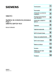
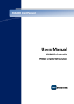
Figure 1-1 shows the SQL7 components as they are used at preparation-time.
At Preparation-time
FDL Source
for Application Catalog
FDL Source
for UFAS files
Relational M o del G enerator
Relational
M odel O bject File
ID S 2 Schem a O bject
& S ource D irectives
Description (STDS)
TDS Preparation
and G eneration
TDS Server
Load Module
Figure 1-1. SQL7 Software Components at Preparation Time
47 A2 51UR Rev02
1-3
SQL7 Administrator's Guide
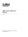
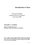
At Run-time
Figure 1-2 shows the SQL7 components and associated gateways as they are used at
run-time.
Bull AIX platform
DDW
Ap plica tion
......
W indow s PC s
DDW
A p plica tion
G C A R u n tim e In te rfac e
T o o th er D P S 70 00
s erv e r no d e s
F rom o th er U N IX D D W
or P C U V T I clien t
ga te w a ys
C lien t
A p p lic a tio n
C lie nt
A pp lic atio n
[D D W /O D B C ]
D D W N et
[D D W /O D B C ]
D DW N et
D D W S Q L 7 G ate w a y
UVTI DA7
G ate w ay
DA7 PC
G a te w a y
O T M /2 LT P Inte rfa ce
IS O /D S A ses sio ns
U V T I D rive r
W in so c k e ts
T o o th e r D P S 7 0 00
s e rve r n o d es
G C O S 7 C o m m u n ica tion L ay er (V C A M )-D S A S e s sion s
DDA GCOS 7
D a ta S erv er T D S 1
.................
T C P /IP So c k e ts
DDA GCOS 7
D ata Se rv e r T D S n
O p en 7 G a tew a y
G C O S 7 SQ L P ro c es so r S e rvic e
DPS 7000/GCOS 7
server site
G C O S 7 D ata M an a g em e n t Fu nc tio n s
U FA S /ID S/II F ile s
U F A S /ID S /II F ile s
M O D E L F iles
M O D E L File s
Open7
U FA S /ID S /II F ile s
M O D E L F ile s
Figure 1-2. SQL7 Software Components at Run Time
1-4
47 A2 51UR Rev02
SQL7 Overview
1.3
ACCESS TO SQL7 SERVICES
The software for DDW/DA7 to access GCOS 7 data performs the following services:
• Model Management (GCOS 7 Administrator)
• Data Server Operations (GCOS 7 Administrator)
• Gateway Server Operations (UNIX/DDW or PC/DA7 Administrator)
The administrator needs to carry out certain preparatory tasks on each service before
SQL7 is ready for use.
This manual describes GCOS 7 administration tasks, for which knowledge of GCOS 7 is
necessary (rather than UNIX or PC).
The preparatory tasks for each service are described in turn.
1.3.1
Model Management
Model Management consists of two distinct parts:
• File Definition Language (FDL) for UFAS files or Application Catalog subfiles, and
Mapping Directive Language (MDL) for IDS/II databases
• Relational Model Generator (RMGEN)
The FDL language describes how the UFAS, or Linked Queued data is stored and
structured. The MDL language describes options which override the RMGEN default
generation rules.
RMGEN is implemented as a GCOS 7 Load Module (LM) with its own GCL command
domain. It is used to build and maintain relational models of UFAS files or IDS/II
databases. The model is a relational view, consisting of relational tables.
RMGEN works by:
• analyzing the FDL description of the UFAS files and generating a control file from it,
• analyzing the IDS/II object schema and the MDL commands (if any), and generating a
control file from them,
• analyzing the FDL description of some of the subfiles of a Linked Queued library
assumed to contain application control data, and augmenting an existing UFAS or IDS2
control file with it.
Before the SQL7 Data Server can run, the files or IDS/II database to be accessed must
be described as a set of relational tables. This is because SQL commands can be
specified and executed only against a relational view of data.
For SQL7, a user is connected to only one such relational database at a time (single-base
access mode). However, using distributed mode processing, the user can view several
47 A2 51UR Rev02
1-5
SQL7 Administrator's Guide
databases of the network as a single database. This is made possible by UNIX or PC
servers or tools (for example, the DDW Distributed Data Manager).
The administrator must carry out certain preparatory tasks for model management.
For a UFAS based model:
• determine the UFAS files that are to be accessible through SQL7,
• use FDL to describe how the data is structured and stored, and to specify which files
are part of which databases (an FDL description defines the set of UFAS files which
build up a database).
• use RMGEN to validate each FDL description. From this, RMGEN automatically
derives the database relational view, which is called the database model. This
derivation is made through built-in correspondence rules. RMGEN then builds a
specific model file, which becomes the only control file you need to access all the
described tables.
For an IDS/II based model:
• identify the IDS/II database that is to be accessible through SQL7,
• determine the IDS/II objects to be accessed. MDL can be used to suppress or rename
objects,
• use RMGEN to validate the MDL commands and to derive the database relational view
(the "model"). This derivation is made using built-in correspondance rules, some of
which can be overriden by the MDL commands.
• the model generated by RMGEN is not the only control structure used to access all the
described tables. The SQL Server activates the IDS/II access method to access the
database, which requires the fully processable IDS/II schema also to be available.
Although stored in a different file from the IDS/II schema, the model is always validated
with respect to the schema before being accepted for use.
Extension for Application Control Data Repository:
Several OpenSQL compliant tools require a data repository for their descriptive objects
(their "metadata"), which they access through a relational interface. SQL7 provides such
a service, known as the Application Catalog Facility. In this context, RMGEN offers a
service to describe data that can be later updated and retrieved through standard SQL
verbs.
• A Catalog Model contains the set of permanent and statically defined descriptions of
the tables needed by a query tool for its metadata. Because these "metadata" strongly
relate to the structure of the accessed user data, the catalog tables are not available in
a stand-alone SQL7 model, they are added to the list of the user tables in an existing
UFAS or IDS2 based model.
• The catalog model is described at source level using a simplified FDL. RMGEN
analyzes this source, and if no error is found, augments an existing model with the
catalog descriptions.
1-6
47 A2 51UR Rev02
SQL7 Overview
• Unlike the UFAS or IDS2 models, a catalog model does not describe already existing
file structures. On the contrary, the data storage structures are derived from the model
descriptions (using SQL7 built-in rules). The repository is a GCOS 7 Linked Queued
file:
-
the data of a catalog table are stored in a subfile of such a Linked Queued file, one
record per tuple,
-
all the subfiles containing the catalog tables described in a given model must
belong to the same Linked Queued file.
To summarize, a user model (the object contained in a permanent model file) describes:
•
a set of UFAS files or an IDS2 database, and
•
(possibly) a number of subfiles of an associated GCOS 7 Linked Queued file
The FDL/MDL syntax and RMGEN are detailed in subsequent sections of this book.
1.3.2
Data Server Operations
The SQL7 Data Server is a GCOS 7 TDS application that handles Open SQL requests
and executes them concurrently.
The SQL Processor is the part of the SQL7 Data Server that analyzes and executes SQL
statements. These statements act on UFAS, Linked Queued or IDS/II data that is
described by a relational model. Some DDL statements (Create / Drop View) update the
database model. See paragraph How Model Files are Used in chapter 5.
Before you can get SQL access to GCOS 7 data, the administrator must also define and
install the SQL7 Data Servers. Several servers can be defined and be simultaneously
active on GCOS 7, and a server can handle one or several databases.
The administrator must carry out the following preparatory tasks for Data Server
operations:
• define the number of data servers to be installed on the GCOS 7 site,
• select the models that each of these servers will serve,
• build a corresponding TDS application for each server, and register it in the GCOS 7
and network catalogs.
1.3.3
Gateway Server Operations
The SQL7 Gateway Servers are the DDW SQL7 Gateway on AIX, and the DA7 Gateway
on PC. These Gateway Servers convert commands and data between the DDW protocol
(GCA) and the "Virtual Terminal" protocol.
Before users can access GCOS 7 data, the administrator must install the SQL7 gateways
on the Bull AIX machines or PCs.
47 A2 51UR Rev02
1-7
SQL7 Administrator's Guide
As an example, the administrator must carry out the following preparatory tasks for DDW
to SQL7 Gateway Server operations:
1.
Select the machines on which the gateways will run.
-
Each AIX machine supports, at most, one gateway. This is because a gateway
can access any number of SQL7 servers.
-
A gateway can communicate with any DDW component that runs on the same
platform and that complies with the GCA/GCF protocol. This means that the
number of possible configurations increases as more machines are involved.
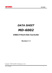
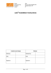
Figure 1-3 shows an example of how this works.
A pp l1
PC
N
N
E
T
A pp l7
DDM
DDM
E
A p p l4
T
A p p l3
A IX
m ach ine
A pp l6
E
N
A p p l2
A pp l5
T
B ull
A IX
S Q L 7 G a tew a y
[to G C O S 7 S Q L S erver(s)]
Figure 1-3. Possible Configuration between Gateways and DDW Components
NOTE:
1-8
Applications 1, 4 & 7 are in single-base access mode. An alternative to the
above configuration could be one gateway per machine (depending on machine
loads and communication costs).
2.
Declare each gateway as a valid correspondent of each SQL7 server it reaches.
These are network access points between the AIX machine and the DPS7000.
3.
Register each gateway as a component of the DDW network using DDW
commands. The DDW network consists of DDW catalogs to be updated.
4.
In a distributed database configuration, ensure that the relevant DDM knows which
GCOS 7 databases are accessible. The DDM table dictionary is updated with DDW
commands, which are described in the DDW manuals (the DDM User's Manual in
this case).
47 A2 51UR Rev02
2. Defining a Model
2.1
THE RELATIONAL MODEL
All UFAS files and IDS/II databases, as well as Application Catalog subfiles, must be
described in a relational way before SQL can access the data they contain. The SQL
Processor needs to know how the data structures for each UFAS file, Linked Queued
subfile and IDS/II database map onto a relational model.
A relational database is called a model, or more specifically, a base model. It consists
of:
• one or more UFAS files, or
• one IDS/II database,
• and optionally, one or more subfiles of a Linked Queued file.
The term "base model" indicates the lowest relational description level that can be applied
to non-relational data. In a base model, the data is represented as relational tables; you
can use a standard SQL SELECT statement to access and retrieve information from
them.
UFAS file models are defined (written) in File Description Language (FDL). The FDL is
the source description of the model.
IDS/II database models are derived from the schema (a binary object stored on a GCOS
7 library subfile), using a default set of rules. These rules can be modified by the
administrator using commands (directives) described in Chapter 4. These directives are
defined (written) in Mapping Directive Language (MDL).
Subfile descriptions are defined (written) in a simplified FDL. They build an Application
Catalog model.
The Relational Model Generator (RMGEN) validates and compiles these definitions for
the SQL Processor. The RMGEN processes it into an object model.
47 A2 51UR Rev02
2-1
SQL7 Administrator's Guide
2.2
UFAS DATA STRUCTURES IN FDL
The FDL source must describe the UFAS data structures so that RMGEN can convert
them into a relational model.
There are six specific elements that allow you to do this:
•
•
•
•
•
•
Model areas
Record types
Fields
Keys
Sets
Virtual fields
These are discussed below.
2.2.1
Model Areas
A model is described in terms of areas.
An area can represent:
• a UFAS sequential file
• a UFAS indexed sequential file.
The administrator chooses the UFAS files that make up a database.
FDL imposes only one constraint on the file grouping; there can be a maximum of 200
files per model.
An FDL text is a set of unconnected descriptions; one for each file.
Area names must be globally unique within the model.
2.2.2
Record Types
An area is made up of one or more record types. Each record type is like a class that
represents a different data structure. For example, COBOL users see these structures as
file record descriptions in the DATA DIVISION of a program.
The type of a physical record can depend on its length or on the value of one or more
fields. Therefore, the record type determines the structures of the data they contain.
You cannot declare a given record type in more than one area.
You cannot re-define a given record type within the model.
2-2
47 A2 51UR Rev02
Defining a Model
2.2.3
Fields
A record type consists of a list of fields. These fields are in the same order as they are
kept within each physical record of that type.
Each field provides a name for an atomic piece of data.
Each field also describes the nature and storage format of that data.
A field can contain only elementary data items. Therefore:
• item group hierarchies within records are not supported because they do not map onto
a relational construct
• repeating groups (arrays of groups of elementary data) cannot be specified directly.
Instead define an elementary item with its own name for each data occurrence.
• As an extension, vectors (one-dimensional arrays of elementary items all having the
same type) can be specified. RMGEN automatically converts a vector into a list of
elementary data items with different names (see the sub-section OCCURS Clause in
chapter 4).
Recognized storage types are those available in the IDS/II or IQS DDL schemas, plus the
numeric FLOAT DPS 7000 standard representations.
A field can also be a virtual field. A virtual field is seen as if it belongs to the physical
record being described. But it is actually stored in another record of a different type. The
relationship between the two records is defined by a set. See the paragraph "Virtual
Fields" further on in this Section.
2.2.4
Keys
A key describes elementary data items that:
• comprise a primary or secondary index of a UFAS indexed file,
• determine the physical record sequence in a UFAS sequential file (when the records
are stored and maintained in sort order),
• it also provides the ASCENDING/DESCENDING sort criteria and information on
duplicates.
The SQL Processor uses keys to optimize query execution; but keys are never directly
referenced in SQL statements.
Keys are named locally within the FDL description, and used as a reference facility in the
FDL syntax.
Keys must be declared in the FDL because:
• a key on a sequential file is purely logical; it has no physical representation and so
cannot be automatically retrieved by the Server,
47 A2 51UR Rev02
2-3
SQL7 Administrator's Guide
• the SQL Processor does not accept file items that overlap key boundaries. If
overlapping occurs, there will be run time errors. So it is much easier to manage the
keys from FDL at the preparation stage,
• although an index, or a sequential order sequence, applies to all records of a given file,
the administrator may want the SQL Processor to ignore it for records of a certain type.
Possible reasons for this include the following:
2.2.5
-
the item and key boundary rule cannot be satisfied,
-
the SQL Processor uses any declared key as a valid order key (there is no way to
specify it as only an access key). The order maintained by a UFAS index is purely
lexicographic, which is therefore suitable primarily for EBCDIC strings. If the
indexed item is of numeric type, the sequence actually maintained may in some
cases differ from the natural numeric order; for example, between negative and
positive values. A selection based on such an index can return wrong or
incomplete results.
Sets
Sets link records of one type (known as Owner records) to records of a different type
(known as Member records) in the same file. See the paragraph "An Example with a SET
Entry" in the Section "Syntax Definitions".
Defining a set in FDL tells the SQL Processor that a logical association exists between
each owner-type occurrence and any number (possibly zero) of member-type
occurrences. A given member occurrence can have only one owner occurrence.
SQL7 supports only one implementation of the Set construct in a UFAS file; that is, the
group (sometimes known as a "set occurrence") formed by an owner and its related
members is characterized by the proximity of one record to the next one. Members
related to a given owner are those record occurrences of the relevant type that
immediately follow the owner record. This is true unless and until one of the following is
encountered:
• another owner occurrence,
• an occurrence of a record-type which is higher in the set hierarchy; that is, owner [of
owner] ...
• end of file.
An FDL set is therefore valid only for relationships that are physically represented in the
file, as already stated.
In a file of SEQUENTIAL organization, the record sequence works on the basis of
physical placement of each record.
In a file of INDEXED organization, the record sequence is maintained by the physical
placement of the primary key values.
2-4
47 A2 51UR Rev02
Defining a Model
NOTE:
Use the FDL set construct only to specify a relationship which:
- cannot be defined in SQL through existing field value equality,
- is physically represented in the file (as previously stated)
Use of the FDL set construct will tend to slow down the execution of SQL
requests.
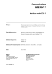
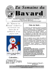
Figure 2-1 illustrates set occurrences in a file where "SET OWNER R1 MEMBER R2" is
specified in the FDL.
R 1 -type reco rd s
1
2
3
4
5
6
7
8 EOF
R 2 -type reco rd s
T h re e set oc cu rre nce s are re p re sen te d :
(1 / 2 ,3 )
(4)
(5 / 6 ,7 ,8 )
Figure 2-1. Set Occurrences
A file can have several sets.
FDL enforces certain rules. These ensure that the relationships between records are
always hierarchical in nature. For example, a record type can be a member in only one
set.
The next Figure shows part of a complex record hierarchy. Notice that record R3 is the
owner of record R4, but is also the member of record R1.
R 1 Type
S E T O w n er R 1 M e m b er R 2
S E T O w n er R 1 M e m b er R 3
R 2 Type
R 3 Type
S E T O w n er R 3 M e m b er R 4
R 4 Type
1
2
3
4
5
6
7
8
9
A
B
C
D
E
F
G
H
EOF
(R 1/R 2 ) s et o ccu rre nce s: (1/5,7 ,8 ,B ) (D /E)
(R 1/R 3 ) s et o ccu rre nce s: (1/2 ,9 ,A ) (D /F )
(R 3/R 4 ) se t o ccurren ces : (2/3,4,6 ) (9/) (A /C ) (F /G ,H )
Figure 2-2. A Complex File Record Hierarchy
The record hierarchy occurrences must be complete with respect to the set descriptions.
47 A2 51UR Rev02
2-5
SQL7 Administrator's Guide
An incomplete hierarchy is one where a particular record occurrence is missing. In Figure
2-2, for example, there might be no R3 occurrence between the R1 and R4 occurrences.
Incomplete hierarchies lead to context-dependent identification rules of the set
occurrences, for which future compatibility is not guaranteed.
Sets are not named in the FDL because:
• sets are declared but are not referenced in other FDL clauses
• a set is unambiguously identified by the Owner type/Member type link. Relationships
are strictly hierarchical.
• the set construct is not a relational object and cannot be referenced in any SQL
statement.
2.2.6
Virtual Fields
The logical (owner/member) join function in standard SQL needs more than the FDL set
declaration to be able to do its work.
SQL needs more information about the link. To provide this, the member record type
must be defined with a virtual field.
FDL uses the SOURCE clause to define a virtual field that uniquely relates the record
occurrence to its owner record occurrence. The value of this item in a member
occurrence is the value of the sending item in the actual owner occurrence.
A SOURCE field acts as a foreign key in the Member table that references a key in the
Owner table. This key is assumed to be a unique key of the owner table (i.e., no two
owner records have the same value for this item).
The set and source constructs are valuable for use mainly with UFAS sequential files.
(On an indexed file, the primary key structure takes care of the kind of association
specified by the set construct, and the data needed to join related records is directly
available.)
Example: Set-based Join Operation
Continuing from Figure 2-2, F1 is a unique key field within record R1.
F1 is also used as a virtual field in R2.
We make the following FDL declarations:
RECORD R1 (F1, F2)
RECORD R2 (F3, F4, F5 SOURCE F1)
UFAS record-types are viewed as tables; and fields as columns.
2-6
47 A2 51UR Rev02
Defining a Model
So, according to the FDL to relational model mapping, we can have:
SELECT F1, F3 FROM R1, R2
=> gives the standard Cartesian product
=> returns 15 rows; that is, 3(R1) x 5(R2)
SELECT F1, F3 FROM R1, R2 WHERE F5 = F1
=> restricts the search to rows associated with the set
=> returns 5 rows:
[F1(1),
[F1(1),
[F1(5),
[F1(5),
[F1(5),
F3(2)]
F3(3)]
F3(6)]
F3(7)]
F3(8)]
SELECT F1, F3 FROM R1, R2 WHERE F5 <> F1
=> eliminates the (owner, member) associations
=> returns 10 rows:
[F1(1),
[F1(1),
[F1(1),
[F1(4),
[F1(4),
[F1(4),
[F1(4),
[F1(4),
[F1(5),
[F1(5),
2.3
F3(6)]
F3(7)]
F3(8)]
F3(2)]
F3(3)]
F3(6)]
F3(7)]
F3(8)]
F3(2)]
F3(3)]
IDS/II SCHEMAS AND MODELS
RMGEN uses the DDL schema object as input. This schema does not need to be
processible (i.e., contain a DMCL description), and can be from IDS/II V1(V40) or IDS/II
V2 (V50 on). The subschema facility is not used by SQL7:
• only the DDL level schema object is loaded at RMGEN time,
• the SQL processor activates the IDS/II access method in the "Subschema All" mode at
request execution time.
SQL7 imposes the following restrictions on the model scope:
• only one IDS/II database can be specified for a given model,
• UFAS files and IDS/II databases cannot be mixed in the same model. Therefore, a
model is either a UFAS model or an IDS/II model.
Using Mapping Directives at RMGEN time, the administrator can suppress or rename
objects of the DDL schema.
47 A2 51UR Rev02
2-7
SQL7 Administrator's Guide
2.4
APPLICATION CATALOG MODELS
The descriptions of the Application Catalog tables are supplied to RMGEN in the form of a
model source text written in simplified FDL (because a number of FDL standard clauses
are meaningless in this context):
• No KEY, SET or Virtual Field construct,
• only elementary items in Record, with data-types restricted to the Open SQL standard
types (i.e. the types of data that can be input to the server),
• one record-type per area
(Record-type <=> Relational Table, Area <=> Table containing subfile)
Table descriptions can be appended as one or several successive models to the UFAS or
IDS2 user model.
2.5
MODEL AND DATA FILE RELATIONSHIP
2.5.1
What to Consider
The following considerations will help in the process of selecting models for the server:
• A given server can serve one or more IDS/II and/or UFAS models.
• The total number of files that can be served by a given server is limited. A server
keeps open all files that it serves while it is running; the files are statically assigned to it.
Due to system table size limits and performance degradation, the maximum number of
files that can be served is upper bound by certain system limits:
-
There is a maximum number of files for a given server due to TDS limits on the
number of controlled files. This is independent of the way the files have been
packaged into different models. Remember that each model file, UFAS data file,
IDS/II area or index is a controlled file, but the Application Catalog file is not.
-
There is a GCOS 7 limit to the number of assigned and active files. This covers all
servers of a given GCOS 7 system.
-
A given TDS cannot support more than 32 IDS/II databases.
• IDS/II access methods can on site coexist but cannot be used simultaneously within the
same SQL7 server step. The "new" access method must be activated as soon as a
new format schema (ie., a schema in 32x format) is active in the list of databases
assigned to the server. Older schemas (ie., schemas in 1Ex format) will then be
automatically converted to 32x format when loaded into core a TDS starting time.
2-8
47 A2 51UR Rev02
Defining a Model
The following considerations will help in making the necessary file packaging trade-off
when describing a UFAS model:
• Group as many candidate files as you can in a single model. Combined functions
(such as join or view based operations) on data described in different models require a
distributed access mode, that is an access level at which a SQL statement can address
several databases simultaneously.
• If possible, package all files into a single model that is always active. Otherwise, set up
a number of models, each of which describes a small number of files.
• Use a single model to group together files that are semantically related or that make
frequent joins to each other. Use programs, PC tools or DDW facilities to associate
data from different models when such associations are rarely needed.
All the catalog tables required by all the applications accessing a given UFAS or IDS2
database must be described in the corresponding UFAS or IDS2 model. The same
Application Catalog models(s) may then have to be added to several user models.
2.5.2
FDL Descriptions and UFAS Physical Files
The same FDL area description (model) can apply to any physical file whose data
structure conforms to that description.
The major advantages of this are:
• the same model can describe different sets of physical files at different times,
• you do not need to maintain lots of virtually identical pieces of FDL source,
• it controls the number of models in existence.
The administrator must enforce the rules that associate models and files. A judicious file
and model naming policy is one way of doing this. Another way is to use the GCOS 7
cataloging facilities. These methods can manage typical cases such as version control,
archiving and the partitioning of data in several identically structured files.
The files actually attached to the model are determined at server launch-time through
static file assignments.
The server checks the UFAS file allocation characteristics (record size, key structure)
against the model. But most of the description (especially the record structures) is
assumed to match the physical data organization.
If there is any inconsistency between the model and the files it describes, rows may be
retrieved incorrectly or may not be retrieved at all. Such inconsistencies can arise when a
physical file structure evolves and the person responsible forgets to update the
corresponding models. It is intended in a future version of SQL7 to provide a utility that
validates file data against an FDL description.
You specify and generate models independently of each other. If your model belongs to a
distributed database, you may have to rename tables at the time you register them into
your global description, as name conflicts can occur between participating models. This
facility is usually provided by the Data Distribution Managers.
47 A2 51UR Rev02
2-9
SQL7 Administrator's Guide
2.5.3
The IDS/II Model and IDS/II Database
RMGEN stamps the newly generated model with the (possibly FORCEd) IDS/II Schema
DDL Reference Date & Time. When the model is loaded by the SQL processor for use at
SQL Server starting time, it is checked against the currently used IDS/II schema to ensure
that they are the same.
Consistency of the DDL and DMCL descriptions with the database is guaranteed by the
IDS/II DBMS itself. The areas actually attached to the model are determined at serverlaunching time through static file assignments (IDS/II database standard usage under
TDS).
2.5.4
The Application Catalog Files
One Linked Queued file can be associated with each model file at SQL7 Server execution
time. SQL7 assumes that all Application Catalog tables described in the model are stored
in that file:
• the catalog tables and their relational structures are known a priori; so they are
statically defined at preparation (RMGEN) time, in the form of a "catalog model",
• the catalog model exists only as a source FDL; after the model description has been
successfully analyzed by RMGEN, it is always merged into an existing (UFAS or IDS2)
model, and the resulting model replaces the previous one with same name in the file.
- Base catalog (ii* views) depicts both the user and the application catalog tables,
- several application catalogs can be successively added to an existing user model,
- at server run-time, all the tables of the extended model can be referenced.
• The catalog tables are permanent tables of the model. As with any table derived from
the UFAS or IDS2 user data file, they cannot be dropped. Also, any name or structure
modification in such a table requires the model to be generated again.
• Tables are public. There is no permanent private table in an SQL7 database.
• The amount of data to be kept in each table should be rather small. Each table is
implemented in a Linked Queued library subfile, and is handled as a sequential file for
which there are not many access optimization capabilities.
• Updates are assumed to be performed by the same user (usually an Administrator),
accessing the tables in an exclusive mode. Remember that GCOS/TDS does not
provide any journalization or concurrent access control facility on subfiles; any access
conflict (namely writer/writer or writer/reader) will cause a transaction to be aborted.
Remember that restrictions exist on update capabilities, especially:
- views cannot be used,
- no cursor-based statements are supported (for more information, see the manual
SQL Supplement for SQL7).
• The Application Catalog Facility is primarily dedicated to providing applications and
query tools with a repository for their metadata. It can be used for any other purpose
which is compatible with the above listed restrictions.
2-10
47 A2 51UR Rev02
Defining a Model
• All the data of a table named <table_name> is contained in one subfile which is also
named <table_name>. All tuples in a table have the same length.
The library record format can be Fixed or Variable, the record-size must be big enough
to contain any table tuple (as big as the longest tuple). For more information, see the
section Storage Structure of the Application Catalog Tuples in chapter 6 for storage
layout.
Remember that the GCOS file COMPACT option is incompatible with the update or
delete operations. Because there may be some cases where no modification (but
insert's) has to be performed on the application catalog file, SQL7 only issues a
warning when it detects the COMPACT option. Update or delete transactions (if any)
will later be aborted due to Data Management errors.
• If the subfile is missing when an Insert command is issued, the subfile is created. In
the other cases, the table is considered as empty. Within the library associated to the
user model, any subfile whose name does not match with the name of a model catalog
table is ignored by SQL7.
Refer to Appendix D for an exhaustive example of how to specify and build an Application
Catalog.
47 A2 51UR Rev02
2-11
SQL7 Administrator's Guide
2-12
47 A2 51UR Rev02
3. FDL/MDL Syntax Elements
This section describes the File Description Language (FDL) and the Mapping Directive
Language (MDL) syntax elements. The following elements apply to both FDL and MDL:
• source format,
• character set,
• punctuation,
• reserved words,
• names,
• literals,
• comments,
• data names,
• data identifiers.
The different types of entry are introduced as they are refered in this section. The entries
themselves are fully described in Section 4.
47 A2 51UR Rev02
3-1
SQL7 Administrator's Guide
3.1
SUITABILITY OF FDL/MDL AS A LANGUAGE
FDL and MDL have two specific advantages for users of the SQL7 product:
1.
it uses familiar syntax
2.
it describes physical data
Familiar syntax
• The major user of FDL/MDL is the GCOS 7 administrator. Administrators are already
likely to be familiar with IDS/II database descriptions and UFAS file descriptions for
IQS, both of which use a CODASYL-standard DDL. For this reason, FDL has been
designed to be as near as possible to a DDL-like syntax; constructs that are
meaningless in the SQL7 context have been discarded.
Describes physical data
• FDL describes the "physical" side of data, not the "relational". And it is this physical
data that is used most often in a COBOL and IDS/II programming context. CODASYLstandard DDL is well suited to this task. By contrast, a number of extensions would
have to be added to the Data Definition (DDL) part of the SQL language to describe file
specifics.
3.2
TYPES OF ENTRY
An FDL base or Application Catalog model is written in File Description Language (FDL).
The language consists of five types of entry:
• One MODEL entry to identify the model.
• One or more AREA entries to define the file(s) or subfile(s).
• One or more RECORD entries to define the record type(s), data items, and storage
structures, and to specify the record-type identification method.
• One or more SET entries to define the links between records.
• One END-MODEL entry to terminate the model description.
The directives to modify the default correspondance rules for the IDS/II schema are
written in the Mapping Directive Language (MDL). This consists of two type of entry:
• SUPPRESS entries, to discard IDS/II elements from the model view,
• ALIAS entries, to rename model tables or columns.
Section 4 gives complete syntax reference information for each type of entry.
3-2
47 A2 51UR Rev02
FDL/MDL Syntax Elements
3.3
FDL/MDL SOURCE FORMAT
FDL/MDL is a free-format language. There are no special fields for sequence numbers or
comment flags.
FDL/MDL is not line-oriented, but the end of line is a separator when it does not occur
within a delimited string. This is described further under "FDL/MDL Punctuation".
Input enclosures and library members containing FDL/MDL must be type DATA or
DATASSF. If not, the Relational Model Generator (RMGEN) does not accept them for
translation.
3.4
FDL/MDL CHARACTER SET
The allowed character set consists of 49 characters.
The set incorporates capital letters of the alphabet, digits, and symbols, as shown below
in Table 3-1:
Tableau 3-1. FDL/MDL Character Set
Character
Name
0, 1, ..., 9
A, B, ..., Z
_
digits
upper-case letters
underscore
space or blank
plus sign
minus sign
comma
semicolon
period or decimal point
quotation mark
left parenthesis
right parenthesis
apostrophe
slash
asterisk
+
,
;
.
"
(
)
'
/
*
Additional characters from the complete DPS 7000 character set can be used in delimited
strings or in the alternate form of names.
Delimited strings include non-numeric literals and comments.
Lowercase letters are automatically converted into their uppercase equivalent, except in
delimited strings or names in alternate form.
47 A2 51UR Rev02
3-3
SQL7 Administrator's Guide
3.5
3.5.1
FDL/MDL PUNCTUATION
Delimiters
An FDL/MDL delimiter indicates the beginning and the end of a protected string.
A protected string is a string of characters in the DPS 7000 character set, preceded and
followed by the delimiter.
If a delimiter is to be included in a string then it must be written twice consecutively.
There are two delimiters:
• The quotation mark.
comments.
Used to delimit alphanumeric and hexadecimal literals, and
• The apostrophe. Used to delimit the alternate form of names.
3.5.2
Separators
A separator has two purposes. It separates words and literals; and it indicates certain
language constructs.
A separator is not significant if it occurs within a protected string. It becomes part of the
string if it is a character. It is ignored if it is at an end of line position.
The separators are:
3.6
Space
One or more blank spaces act as a separator. A space
can also precede or follow any other separator.
Comma
A comma is an optional separator between data identifiers.
Semicolon
A semicolon can be used as a space.
Period
A period followed by a space or the end of a line is
mandatory to terminate an entry or subentry.
Left and Right Bracket
Pairs
They delimit the subscript values of an identifier.
End of Line
The end-of-line character works in the same way as a
space.
FDL/MDL WORDS
An FDL/MDL word consists of up to 32 contiguous characters.
3-4
47 A2 51UR Rev02
FDL/MDL Syntax Elements
Valid characters are:
•
•
•
•
A through Z
0 through 9
hyphen
underscore
The first character must be alphabetic (A through Z).
Lowercase letters are accepted, but are automatically converted into the corresponding
uppercase letters.
Examples: Valid words
A
A_B
A_
Z9999
RECORD-TYPE
Examples: Invalid words
-A
(first character not alphabetic)
A(B (bracket not allowed)
A+B (+ not allowed)
2A
(first character not alphabetic)
47 A2 51UR Rev02
3-5
SQL7 Administrator's Guide
3.6.1
Reserved Words
There are two kinds of reserved words:
• keywords
• optional words
Reserved words can be used but must not appear as user-defined names. FDL and MDL
have different sets of reserved words. Refer to Appendix A for a complete list of FDL and
MDL reserved words, with their abbreviations.
3.6.1.1
Keyword
A keyword is a word that is mandatory in phrases where it appears.
Within each syntax format (see Section 4), keywords are shown as uppercase and
underlined.
3.6.1.2
Optional Word
An optional word is a word that is optional in phrases where it appears.
Within each syntax format (see Section 4), optional words are shown as uppercase and
not underlined.
Misspelling of an optional word or replacing it by another word is not allowed.
3.6.2
Names
There are three categories of name:
• Language names
• SQL names
• System names
3-6
47 A2 51UR Rev02
FDL/MDL Syntax Elements
3.6.2.1
Language Names
Language names are not referenced outside of the FDL/MDL syntax within the scope of
this product.
A language name can be any FDL/MDL word which is not a keyword and which is not
longer than 30 characters.
Key-names are classed as FDL names, all IDS/II names are classed as MDL names.
3.6.2.2
SQL Names
SQL names can be referenced in the SQL syntax.
An SQL name is an FDL/MDL word that is not an SQL keyword, and which satisfies the
following rules:
1.
Valid characters are:
-
A through Z
0 through 9
underscore
2.
The hyphen character is not allowed.
3.
The first character must be alphabetic (from A through Z).
FDL record-names and data-names, or MDL aliases, are classed as SQL names.
A complete list of the SQL reserved words is given in the SQL Supplement for SQL7.
3.6.2.3
System Names
System names are referenced in the server execution environment (that is, GCOS 7
and/or DDW).
The rules for System names are specified in Section 4, along with the FDL clauses that
define them.
Model-names and FDL area-names are classed as System names.
47 A2 51UR Rev02
3-7
SQL7 Administrator's Guide
3.6.3
Alternate Form of Names
There is an alternate form of names in FDL/MDL. It is defined by a string of the allowable
characters in the DPS 7000 character set, delimited by single quotes. Its length may not
exceed the maximum length for its category.
No lowercase to uppercase conversion is allowed.
If a user-defined name is identical to a reserved word (see the list in Appendix A), the
name must be written in the alternate form.
Example: FDL reserved word in alternate form
MODEL NAME IS 'MODEL'.
System names must comply with their own rules, whether they are in regular or in
alternate form.
SQL names - even in the alternate form - must also obey the following rules:
• cannot be a SQL reserved word
• only A through Z, 0 through 9, and underscore are allowed
• first character must be alphabetic
Examples: Valid SQL names
'MYNAME'
'RECORD'
Examples: Invalid SQL names
3-8
'Myname'
(lowercase letters not allowed)
'WORK.MODEL'
(period character not allowed)
'A-B'
(hyphen character not allowed)
'2A'
(first character is not alphabetic)
47 A2 51UR Rev02
FDL/MDL Syntax Elements
3.7
FDL/MDL LITERALS
A literal is a string of characters representing a value.
There are three types of literal:
• Alphanumeric
• Numeric
• Hexadecimal
3.7.1
Alphanumeric Literals
An alphanumeric literal represents a character string containing a maximum of 127
characters chosen from the DPS 7000 character set.
It is delimited by quotation marks. The value is the string of characters. The length of the
string is the number of characters within the string.
If a quotation mark forms part of the string, there must be two consecutive marks for each
occurrence. Only one of the two marks is counted when determining the length of the
string. See the examples below.
NOTE:
Trailing blanks are meaningless when comparing two strings. The comparison
rules state that the shorter string is right-padded with blanks before the
comparison takes place.
So, "AB
", "AB ", and "AB" are identical strings.
Examples:
"JANUARY 1ST"
(value is JANUARY 1ST)
(length is 11)
"CODE ""4"""
(value is CODE "4")
(length is 8)
47 A2 51UR Rev02
3-9
SQL7 Administrator's Guide
3.7.2
Numeric Literals
A numeric literal represents a character string containing a maximum of 30 characters
from the digit set.
Valid characters are:
• 0 through 9
• the plus sign (+)
• the minus sign (-)
• the decimal point (.)
A decimal point must be followed by at least one digit.
If there is no plus or minus sign, the value is assumed to be positive.
The value represented is the conventional algebraic value.
Examples: Valid numeric literals
1
1.0
+322
+0.004
-5789.333
-.005
Examples: Invalid numeric literals
3-10
122.
(at least one digit must follow the decimal point)
+32.1A4
(alphabetic character not allowed)
47 A2 51UR Rev02
FDL/MDL Syntax Elements
3.7.3
Hexadecimal Literals
A hexadecimal literal represents a string containing a maximum of 254 characters from
the following set:
• 0 through 9
• A (a) through F (f)
A hexadecimal literal represents a character string - so it is used only for character string
data.
It is delimited by double quotation marks.
followed by the uppercase X character.
The final double quotation mark must be
There must be an even number of characters in the string, because the value represented
is the EBCDIC equivalent of each pair of characters in the string. So the length of the
string is the number of characters divided by two.
A hexadecimal string can be used to represent characters for which an external symbol
does not exist, or is not available on an input device.
Example: Hexadecimal literal
"D481998388"X
47 A2 51UR Rev02
(value is March)
(length is 5)
3-11
SQL7 Administrator's Guide
3.8
FDL/MDL COMMENTS
Comments serve as in-line documentation.
A comment can be coded wherever the space character appears as a separator. A
comment consists of three distinct parts:
• the reserved word COMMENT
• 0 to n spaces
• text, delimited by double quotation marks
There is no limit to the length of a comment; it may be spread over several lines, and
continues until a closing double quotation mark is met.
Embedded comments are not recognized. Everything that follows the heading delimiter is
treated as part of the comment until the end delimiter is met.
Example: Use of comments
COMMENT
"***********************
* <PERSON> MODEL
*
***********************"
RECORD NAME IS PERSON.
02 NAM TYPE CHAR 30. /* Family Name */
02 SEX TYPE CHAR 1. COMMENT "VALUE ""M"" IF MALE
VALUE ""F"" IF FEMALE"
There are two other points to note in the example:
• the use of two consecutive double quotation marks to be able to include one double
quotation mark in the text itself
• and an alternative way of introducing comments - where text is inserted between /* and
*/.
3.9
FDL/MDL DATA NAMES AND IDENTIFIERS
A data-name is a user-defined name for a data item.
A data identifier refers to a data item declared in the model. It consists of only a dataname.
The format of a data identifier is as follows:
Data-name
3-12
47 A2 51UR Rev02
4. Syntax Definitions
This section describes the syntax of the FDL/MDL language used to:
• describe the UFAS file structures (FDL),
• specify supported extensions of the UFAS file structures (FDL),
• specify Application Catalog tables (FDL),
• specify mapping directives for an IDS/II database into a relational model (MDL).
47 A2 51UR Rev02
4-1
SQL7 Administrator's Guide
4.1
FDL/MDL SYNTAX NOTATION
SQL7 File Definition Language (FDL) and Mapping Directive Language (MDL) uses
syntax notation that conforms to the GCOS 7 language notation standards that apply to
DDL, TDS, and so on.
These are the rules:
• The elements that make up a clause consist of uppercase words, lowercase words,
special symbols and special characters.
• All underlined uppercase words are reserved words, which are required when the
format is used.
• Uppercase words that are not underlined are optional reserved words. They need not
be used.
• Lowercase words are generic terms that must be replaced by appropriate names or
values.
• FDL/MDL uses specific symbols to enclose portions of a general format.
symbols are as follows:
These
Brackets:
[a] At least no occurrences
[b]
[c] At most one occurrence
Braces:
{a} At least one occurrence
{b}
{c} At most one occurrence
Ellipsis (...) indicates that repetition is allowed. The portion of the format that can be
repeated is determined by the bracket or brace which logically matches the bracket or
brace to the immediate left of the ellipsis.
4-2
47 A2 51UR Rev02
Syntax Definitions
4.2
4.2.1
SEQUENCE RULES
FDL
Each area, record-type, and set-type in the model requires a separate entry.
An entry or a sub-entry consists of one or more clauses that describe its attributes.
Clauses may appear in any sequence provided that the first clause names the entry or
sub-entry.
All entries and sub-entries are terminated by a period, followed by a space or end of line.
The following sequence rules apply to the various types of entry in a model:
• The first entry is the MODEL entry.
• A RECORD entry is followed by at least one FIELD sub-entry. The order of the FIELD
sub-entries within a RECORD entry is meaningful, as it reflects the physical order of the
atomic data items in the storage record.
• The last entry is the END-MODEL entry.
4.2.1.1
Duplicate Names
Duplicate names only apply to FDL. You can use the same name more than once.
However, the following constraints apply:
• You cannot duplicate area names, record names or key names.
• A data item name cannot duplicate the name of a record.
• A RECORD entry cannot have duplicate data names within it.
• Objects of different types can have duplicate names.
• A data item within a RECORD entry can duplicate the name of a data item within a
different RECORD entry.
47 A2 51UR Rev02
4-3
SQL7 Administrator's Guide
4.2.1.2
Maximum Number of Names
This only applies to FDL. The list below shows the maximum number of names allowed
for different types of name.
4.2.2
Name
Maximum Number Allowed
Area-names
200 (limited by the number of active files
supported by the data server)
Record-names
2048
Key-names
2048
Data-names within a record-type
1023
Warning: any tool or DDW component that
strictly complies with the Open SQL limits
cannot specify requests on tables involving
more than 127 columns.
MDL
Each mapping directive is either SUPPRESS or ALIAS.
A directive entry consists of one clause that describes its attributes. It is terminated by a
period, followed by a space or end of line.
No entry is mandatory. The directive file can be missing or empty. In this case, the
mapping default rules apply.
Directives are independent from each other and can be submitted in any order within the
MDL command file. However, to avoid ambiguous requests and to simplify the error
detection and reporting, RMGEN always processes the SUPPRESS commands first. As
a consequence, a fatal error (instead of a warning) will be issued if you first ALIAS an
object that you then SUPPRESS. It is therefore recommended that you specify all the
SUPPRESS entries first.
No specific order is required among the SUPPRESS entries, or among the ALIAS entries.
4.3
LANGUAGE STRUCTURE SUMMARY
The complete, ordered FDL structure for a model can be summarized as follows:
MODEL Entry,
AREA Entry ...,
RECORD Entry and any FIELD sub-entries...,
[SET Entry] ...,
END-MODEL Entry.
MDL consists of two types of entry:
SUPPRESS Entry,
ALIAS Entry.
4-4
47 A2 51UR Rev02
Syntax Definitions
4.4
ENTRY DESCRIPTIONS
These descriptions are valid for both FDL and MDL. Each entry and sub-entry clause is
presented in the following way:
Function
A brief description of the purpose of the clause.
General Format
A presentation of the FDL syntax that applies to the clause.
Also, how the elements that make up the clause can be
arranged.
Specific Rules
The rules that amplify or restrict the use of the elements
within the General Format.
General Rules
The rules that amplify or restrict the functions attributed to the
General Format and its elements.
The subdivisions of a clause are presented, and must be written, in the order they are
shown.
4.5
MODEL ENTRY
This is applicable to FDL only.
Function
This mandatory entry names the model. All external references to this model use this
name.
General Format
MODEL NAME IS model-name .
Specific Rules
• This entry must appear first in the model text.
• A MODEL entry comprises only the mandatory NAME clause.
• Model-name is a system name of maximum length 15 characters. It must be an
FDL/MDL word (although the hyphen and underscore characters are not allowed).
• The alternate form of names can be used if the name does not comply with the
FDL/MDL formation rules.
General Rules
• The MODEL entry names the model that comprises all the FDL entries that appear
after the MODEL entry and before the END-MODEL entry.
• A (remote) client connects to the database using this model-name.
• The model-name of an Application Catalog model is no longer used after the catalog
model has been merged into a user model.
47 A2 51UR Rev02
4-5
SQL7 Administrator's Guide
4.6
AREA ENTRY
This is applicable to FDL only.
Function
This entry names an area within the model and specifies its organization.
General Format
AREA NAME IS area-name
{SEQUENTIAL
}
[ ORGANIZATION IS {
}
{INDEXED USING key-name}
]
.
Specific Rules
• This entry comprises the mandatory NAME clause and the optional ORGANIZATION
clause.
• The area-name cannot duplicate another area-name in the model.
• There is one AREA entry for each UFAS file that builds up the database, or for each
table of an Application Catalog model.
• If the ORGANIZATION clause is omitted, the default is SEQUENTIAL.
• The ORGANIZATION clause is not allowed in an Application Catalog model.
• Key-name locally names the primary key of an indexed file. Key-name is an FDL name
which references the key in the record descriptions. The item names that form the key
are given in each record.
• Area-name is a system name with a maximum length of 8 characters. It must be an
FDL/MDL word (the hyphen and underscore characters are not allowed).
• The alternate form can be used if the name does not comply with the FDL/MDL
formation rules.
General Rules
• Areas declared in a model may have different ORGANIZATION clauses.
• Area-name is the name used by the SQL7 server to associate the current description
with a physical UFAS file. For more information, see chapter 7. In an Application
Catalog model, area entry is required only for FDL syntax homogeneity.
• The key-name specified as the primary key of the indexed file must be referenced in at
least one record type of the area (through a KEY clause). If no such reference can be
defined, then the file must be declared to have SEQUENTIAL organization (and no
alternate key can be described).
4-6
47 A2 51UR Rev02
Syntax Definitions
4.7
RECORD ENTRY
This is applicable to FDL only.
Function
This entry names a record and describes its characteristics.
General Format
RECORD NAME IS record-name
[WITHIN area-name]
{ASCENDING }
[KEY key-name IS {
} data-identifier-1
{DESCENDING}
[THRU data-identifier-2]
DUPLICATES ARE [NOT] ALLOWED
]...
[RECORD-TYPE DEFINED BY
{SIZE
}
{
}
{CONTENT OF data-identifier-3 [THRU data-identifier-4]}
{
[data-identifier-5 [THRU data-identifier-6]]... }
{OTHERWISE
} ]
.
General Rules
• The contents of a physical record of a given type are defined by one or more data
enties. A null length record is not allowed.
• The maximum record size is 32767 bytes. Remember that in Open SQL environments
(DA7, virtual DDW), the size of each output data tuple must not exceed 2k bytes.
• At least one named data-item (that is, not a FILLER) must be specified within a record.
• Only RECORD NAME and WITHIN clauses are accepted in an Application Catalog
model.
47 A2 51UR Rev02
4-7
SQL7 Administrator's Guide
4.7.1
RECORD NAME Clause
Function
This clause names a record-type in the model.
occurrences of the record-type in the area.
The record-name is used for all
General Format
RECORD NAME IS record-name
Specific Rules
• Record-name is a SQL name with no more than 18 characters; to avoid any conflict
with catalog tables automatically available within each model, record-name must not
begin with the prefix "II" (or "ii") or "HH" (or "hh").
• The record-name cannot duplicate another record-name in the model. SQL statements
use it as a table-name.
• The model must have at least one record-name.
4.7.2
WITHIN Clause
Function
This clause names the area where occurrences of the record-type are found.
General Format
WITHIN area-name
Specific Rules
• This clause names an area for which an AREA entry is included in the model.
General Rules
• The WITHIN clause is mandatory only when the model has more than one area.
• This clause specifies the area where all record occurrences of this type can be
retrieved.
4-8
47 A2 51UR Rev02
Syntax Definitions
4.7.3
KEY Clause
Function
This clause specifies a sort control key for the occurrences of the record-type being
described. It also lists the data items (within the record-type) that form this key.
General Format
{ASCENDING }
KEY key-name IS {
}
{DESCENDING}
data-identifier-1
[THRU data-identifier-2]
DUPLICATES ARE [NOT] ALLOWED
Specific Rules
• key-name is an FDL name.
• The data items referenced by data-identifier-1 and data-identifier-2 must be declared
within the current RECORD entry.
• If the THRU option is specified, data-identifier-2 must be different from data-identifier-1,
and must follow it in the RECORD entry.
• The total length of the key must be less than 256 bytes. The length is the sum of all the
component data-item storage sizes.
• The key-name cannot duplicate another within the current RECORD entry.
• The DESCENDING option can be specified only for an area of SEQUENTIAL
organization. Indexed keys are always ASCENDING.
• When 2 KEY clauses have the same key-name, they describe the same key.
47 A2 51UR Rev02
4-9
SQL7 Administrator's Guide
General Rules
• Field entries that belong to a key must represent permanently valued items of the
record type with fixed length. They must contain none of the following:
-
an ADJUSTABLE phrase,
a NULL clause with the ABSENT option,
an OCCURS clause.
• It is not recommended to use nullable fields as key components.
• The data-identifiers are declared in order of decreasing significance (major to minor
key).
• Field entries that belong to a key must not contain a SOURCE clause.
• Descriptions of the same key in different RECORD (that is, 2 or more KEY clauses with
the same key-name) must have the same:
-
length
ordering criteria (ASCENDING/DESCENDING)
option for duplicates
offset of the first named field component in each record-type where it is declared
• The first component of two different keys that relate to record-types in the same area
cannot share the same offset.
• The same key must not be described for record-types belonging to different areas.
• No more than one key can be described for record-types in a SEQUENTIAL area.
• KEY clauses describing the primary key (named in the area ORGANIZATION clause)
of an indexed area must have the options ASCENDING and DUPLICATES NOT.
• A secondary key can be declared if a UFAS secondary index has been created and is
active on the corresponding physical file.
• When a key is specified in a given type of record, the SQL Processor may use it to
optimize certain access paths to records of that type. The SQL Processor assumes
that the key-maintained order matches the expected order according to the data-items
that make up the key. If this is not true, do not specify a key.
4-10
47 A2 51UR Rev02
Syntax Definitions
Recommended key usage
Key Component Type
Recommended Key Usage
CHARACTER
Use if the standard collating sequence is
enforced. Avoid if index enforces a non
EBCDIC order.
UNSIGNED (UN)PACKED DECIMAL
Usage OK (if normalized representation
and neither BLANK WHEN ZERO nor
JUSTIFIED option).
BINARY
Use if all values have same sign.
Avoid if positive and negative values are
mixed. (This is because a negative value
representation is always 'greater' than any
positive value representation.)
FLOAT
Use, but only if all values are positive and
have been normalized.
SIGNED (UN)PACKED DECIMAL
Use, but only if all values are positive and
have been normalized, and if neither
BLANK WHEN ZERO nor JUSTIFIED
option.
PACKED-2 DECIMAL
Usage OK (if normalized representation).
Data normalized representations, referenced in this rule, are those delivered by machine
relevant instructions (see tables 4-1 and 4-2).
• FDL key descriptions are checked for conformity against the actual file characteristics
when the SQL7 Server opens the file. The SQL Processor will ignore the key and send
a warning if the physical key is missing or if it has different attributes (for example,
DUP, ASC, length) from those defined in the FDL.
• The SQL Processor ignores the key on a sequential file but primary or secondary multicomponent keys on indexed files can be used for request optimization when a key
"leftmost" component is specified in the query "where" clause.
47 A2 51UR Rev02
4-11
SQL7 Administrator's Guide
4.7.4
RECORD-TYPE Clause
Function
This clause specifies how the currently described record-type can be attributed to a
physical record occurrence.
General Format
RECORD-TYPE DEFINED BY
{SIZE
}
{
}
{CONTENT OF data-identifier-3 [THRU data-identifier-4]}
{
[data-identifier-5 [THRU data-identifier-6]]... }
{OTHERWISE
}
Specific Rules
• The data items referenced by data-identifier-3, data-identifier-4, data-identifier-5, dataidentifier-6... must be declared within this RECORD entry. They cannot be nullable and
must be valued in any occurence of the type (i.e. a NULL clause or ADJUSTABLE
phrase must not be specified either implicitely or explicitely). They must not contain an
OCCURS clause.
• If the THRU option is specified, data-identifier-4 must follow data-identifier-3 in the
currently described RECORD entry. (Similarly, data-identifier-6 must follow dataidentifier-5, and so on.)
• Items can appear once only in the item list (data identifiers). Items delimited by the
THRU option must not overlap other items in the list.
• Data-types of data-identifier-3, data-identifier-4, data-identifier-5, data-identifier-6 and
intermediates cannot be of FLOAT type.
• Data sub-entries describing data-identifier-3, data-identifier-4, data-identifier-5, dataidentifier-6 and intermediates must not contain a SOURCE clause.
• The total length of the record check key; that is, the sum of all the component data-item
storage sizes must be less than 256 bytes.
• The RECORD-TYPE clause is mandatory only if at least two record-types in the same
area have the same description size.
• The OTHERWISE option cannot be specified for more than one record-type in the
same area.
4-12
47 A2 51UR Rev02
Syntax Definitions
General Rules
• The run-time data manager must determine the record-type of the physical record
being accessed. The RECORD-TYPE clause specifies the condition that the currently
described record-type (among all the possible record-types in the area) must satisfy for
it to be attributed to the record.
• Different SIZE or CONTENT options can be specified in the RECORD-TYPE clauses of
the different record-types in the same area.
• If the SIZE option is specified, the record can be considered to be of the currently
described type if its actual size equals that computed from the record-type description
(including FILLERS). SIZE is the default option. See rules about run-time type
assignment.
• The SIZE option cannot be specified, or left as the default, for either of two record-types
in the same area whose sizes are equal.
• If the CONTENT option is specified, the record type is determined by the value of a
"record check key" contained in the record. This key consists of the data entries
denoted by data-identifier-3 (data-identifier-5...), and if the THRU option is specified, by
all data entries (except FILLERs) in the record starting from data-identifier-3 (dataidentifier-5) and ending with data-identifier 4 (data-identifier-6).
• The SIZE option cannot be specified for a record type with variable occurrence size,
which means that it includes a field entry with an ADJUSTABLE or (implicit or explicit)
NULL WHEN ABSENT clause. For such record types, either the CONTENT or the
OTHERWISE option must be specified.
• If the OTHERWISE option is specified, the record is considered to be of the currently
described type:
-
if it can be assigned to no other record type of the area (all assignment criteria have
failed), and
-
if its actual size is greater than or equal to the description minimum length. This
minimum length takes the following cases into account:
. the lowest size of a trailing ADJUSTABLE item (1 byte),
. the lowest size of a trailing NULL WHEN ILLEGAL (truncated) item (1 byte)
. the possible absence of NULL WHEN ABSENT item(s).
Example: if the record-type is the only one specified in an area, and if its
description only contains CHARACTER n ADJUSTABLE, then all records with non
zero length are assigned this type.
• If the CONTENT option is specified, each data item that is part of the record check key
must contain a VALUE clause (see further on). The VALUE clause indicates the valid
values for this record-type.
47 A2 51UR Rev02
4-13
SQL7 Administrator's Guide
• If the CONTENT option is specified, the record can be considered to be of the currently
described type if all the data entries that comprise the record check key (see rules on
run-time assignment):
-
exist in the record
satisfy their value constraints (as specified in their respective VALUE clauses).
• Items referenced in the different record check keys of record-types belonging to the
same area do not need to be identical in number, type, length and position (offset) in
their respective records.
• Run-time assignment rule: RMGEN does not check that the identification values allow
for unique record typing:
-
Example 1: a given byte of the Data Management record can be specified as a
record check key with values A to C for record type R1 and values B to D for record
type R2. Hence a value byte value C could denote a record type R1 or R2.
-
Example 2: 2 FDL records can be specified with the same description size; one
being identified by SIZE, the other by CONTENT.
To avoid ambiguity, the following rule applies at run-time: the record-type definitions
are tested against the physical record in the sequence in which they appear in the
model; the assigned type is then the first one whose definition condition is satisfied by
the physical record data or size.
• If a record is found which does not belong to any of the established record-types, it is
ignored. SQL7 does not need to have all the records of a physical data file described.
• When the run-time data manager has recognized the record-type, the record data is
checked against the corresponding description. All SQL-visible items (that is, nonFILLER items) must be available with legal storage formats, except for items which are
specifed with the NULL WHEN ABSENT or NULL WHEN ILLEGAL clause. If any data
does not fit with the type description, the record is ignored and a warning is sent. It
follows from this rule that you do not need to specify a trailing FILLER in a description
where RECORD-TYPE is defined by CONTENT.
• For performance purposes, you are recommended to first declare all the record types
of an area whose types are defined by size. (RMGEN notes this and does not trigger
any checking of the contents).
4-14
47 A2 51UR Rev02
Syntax Definitions
4.8
FIELD SUB-ENTRY
Function
This entry names a field which is subordinate to a record or to a containing data item. It
describes the item characteristics.
General Format [1]
{ data-name-1
}
{ FILLER
}
[02]
{{
{UNPACKED}}
}
{{[UNSIGNED]{[PACKED]}}
}
{{
{PACKED-2}} DECIMAL integer-1
}
{{
}
[integer-2]
}
{{
}
[BLANK WHEN ZERO] }
{{
}
[JUSTIFIED [RIGHT]]}
{{
{UNPACKED}}
}
{{SIGNED
{
}}
}
{{
{[PACKED]}}
}
{
}
{
{SINGLE
}
}
TYPE IS { FLOAT {DOUBLE
} PRECISION
}
{
{QUADRUPLE}
}
{
}
{ [SIGNED] BINARY {15}
}
{
{31}
}
{
}
{ CHARACTER integer-3 [FIXED|VARIABLE][ADJUSTABLE]
}
[VALUE [NOT] literal-1 [THRU literal-2]
[literal-3 [THRU literal-4]]...]
{ SMALLINT }
[SQL-TYPE IS { INTEGER } ]
{ FLOAT
}
[NULL WHEN
{
{
{
{
ABSENT
BLANK
ILLEGAL
VALUE literal-5
}
} ]
}
}
[OCCURS integer-4 TIMES [DEPENDING ON data-name-2]]
General Format [2]
[02] data-name-3
47 A2 51UR Rev02
SOURCE IS data-name-4
4-15
SQL7 Administrator's Guide
General Format [3]
[02] data-name-5
{ [SIGNED] BINARY {15}
}
{
{31}
}
TYPE IS { FLOAT DOUBLE PRECISION
}
{ CHARACTER integer-5 [FIXED|VARIABLE]}
[NULL ALLOWED]
General Format [3] must be used in Application Catalog models.
4.8.1
Data-name Clause
Function
To name a data item within the record.
General Format
{ data-name }
[02] {
}
{ FILLER
}
Specific Rules
• Data-name is a SQL name.
• A data-name must be unique among the data-names declared for this record. The
name cannot be a record-name of the model.
General Rules
• A data sub-entry can only describe an elementary data item (that is, an item
representing an atomic value).
• SQL will never access FILLER items. They specify zones in the physical record which
are ignored by the SQL Processor. They can represent either data not available for
query, or extra bytes retained for keeping halfword or word alignment of data.
• The FILLER option is not allowed in an Application Catalog model.
4-16
47 A2 51UR Rev02
Syntax Definitions
4.8.2
TYPE Clause
Function
To describe the storage characteristics of, and the category of value represented by, an
elementary data item.
General Format}
{{
{UNPACKED}}
}
{{[UNSIGNED]{[PACKED]}}
}
{{
{PACKED-2}} DECIMAL integer-1
}
{{
}
[integer-2]
}
{{
}
[BLANK WHEN ZERO] }
{{
}
[JUSTIFIED [RIGHT]]}
{{SIGNED
{UNPACKED}}
}
{{
{[PACKED]}}
}
{
}
{
{SINGLE
}
}
TYPE IS { FLOAT {DOUBLE
} PRECISION
}
{
{QUADRUPLE}
}
{
}
{ [SIGNED] BINARY {15}
}
{
{31}
}
{
}
{ CHARACTER integer-3
[FIXED|VARIABLE]
}
{
[ADJUSTABLE]
}
Specific Rules
• Integer-1 and integer-3 must be UNSIGNED DECIMAL constants with values greater
than zero. The maximum value varies according to the data type and is specified
below in the General Rules.
• Integer-2 is a SIGNED DECIMAL constant.
• The two options BLANK WHEN ZERO and JUSTIFIED RIGHT can both be specified
together and in any order.
• The JUSTIFIED option is allowed only for the UNPACKED DECIMAL data type.
• The two options FIXED | VARIABLE and ADJUSTABLE can both be specified together
and in any order.
• When the FIXED | VARIABLE option is not specified, then the VARIABLE characteristic
is admitted.
• If the ADJUSTABLE option is specified, then the containing record type cannot have
the RECORD-TYPE DEFINED BY SIZE option.
• If the ADJUSTABLE option is specified for this item, then all items following it in the
current record description automatically inherit the NULL WHEN ABSENT
characteristics.
47 A2 51UR Rev02
4-17
SQL7 Administrator's Guide
General Rules
• The following features are not supported in Application Catalog models:
-
DECIMAL type,
-
FLOAT type with SINGLE or QUADRUPLE PRECISION format,
-
the ADJUSTABLE option of the CHARACTER type.
• The TYPE clause defines a numeric data item (DECIMAL, BINARY, or FLOAT) or a
string data item (CHARACTER). For readers more familiar with COBOL than DDL
terminology, Figure 4-1 expresses the FDL storage data-types in terms of COBOL
Picture and Usage declarations.
• DECIMAL specifies an exact numeric data item with a decimal base. DECIMAL data
items correspond to COBOL PIC 9 items.
• Integer-1 specifies the number of significant digits to be maintained for all values of a
data item. The maximum value of integer-1 is 30.
• Integer-2, when specified, indicates the scaling factor of a DECIMAL data item.
Integer-2 can be any value in the range -29 to 30.
-
When integer-2 is negative, the decimal point is positioned integer-2 places to the
right of the rightmost digit. (DECIMAL 4,-1 means PICTURE 9999P in COBOL
terms.)
-
When integer-2 is positive, the decimal point is positioned integer-2 places to the
left of the rightmost digit. (DECIMAL 4,1 means PICTURE 999V9 in COBOL
terms.)
-
When integer-2 is zero, or when not specified, the decimal point is positioned
immediately to the right of the rightmost digit.
-
In Figure 4-1, m represents integer-1; p represents the absolute value integer-2.
For example, 12.34 -> 4 digits -> DECIMAL 4,2 and 1200 -> 4 digits -> DECIMAL
2,-2.
• Integer-1 and integer-2 must be such that the total number of digits necessary to
represent the value does not exceed 30. For example, DECIMAL 30,29 is acceptable
as it takes 30 digits to represent it, but DECIMAL 30,-1 is not acceptable since it takes
31 digits to represent it.
• The keywords SIGNED/UNSIGNED and PACKED/PACKED-2/UNPACKED specify the
internal format of the data item. Refer to Table 4-2 for storage sizes.
• When the BLANK WHEN ZERO option is specified for DECIMAL data, the all-spaces
string in the item area is not considered as an illegal decimal representation, but is
interpreted as the zero value. When the item is used as a key component, the option is
ignored and SQL7 encodes the zero value in its standard decimal format.
• When the JUSTIFIED option is specified, the decimal value representation is right
justified within the item area, and the leftmost padding spaces (if any) are considered
as zero digits. If the item value is to be submitted as a key, it is fully encoded as a
decimal (i.e. with leftmost zero digits).
4-18
47 A2 51UR Rev02
Syntax Definitions
• FLOAT specifies an approximate numeric item corresponding to COBOL COMP-9,
COMP-10 or COMP-15, depending on the precision. Refer to Table 4-2 for the
represented value characteristics.
• BINARY specifies an exact numeric item with a binary base. BINARY items
correspond to COBOL COMP-1 and COMP-2. They contain signed integer values in 2byte (15 bits plus sign bit) or 4-byte (31 bits plus sign bit) form.
• CHARACTER specifies a string data item. CHARACTER items correspond to the
COBOL PIC X family. A character data item is assumed to contain characters from the
full EBCDIC character set (including the non printing configurations); any comparisons
are made using the EBCDIC collating sequence.
• Integer-3 gives the length of the string data item. The maximum value of integer-3 is
2000.
• CHARACTER VARIABLE (the default and already existing option) specifies a string
with integer-3 character maximum length. The rightmost spaces, (if any) are
considered as padding characters, and they are stripped from the data value. An allspaces string is considered as a one-space string.
• CHARACTER FIXED specifies a string with integer-3 character length. The rightmost
spaces (if any) are part of the data value.
• ADJUSTABLE specifes that the actual length of the string value is to be deduced from
the size of the data management containing record, when the item is the rightmost one
available in the record occurence.
-
For a FIXED CHARACTER item, the read value is right padded with spaces to build
an integer-3 character string value.
-
For a VARIABLE CHARACTER item, the read value is considered as the item
occurence value.
If no character is present in the record occurence to represent the item value, then the
item is considered as missing (empty strings are not supported).
• All data items are aligned on a byte boundary when they appear in the record.
• If the clause relates to an Application Catalog table column, its purpose is not to
describe existing data, but to specify an external type from which RMGEN determines a
storage representation. See the paragraph Storage Structure of the Application
Catalog Tuples in chapter 6.
47 A2 51UR Rev02
4-19
SQL7 Administrator's Guide
Example: Alignment
RECORD NAME IS record-name-1...
02 Display-item-1 TYPE IS CHARACTER 3.
02 Decimal-item-2 TYPE IS SIGNED PACKED DECIMAL 5,+2.
02 Binary-item-3 TYPE IS SIGNED BINARY 31.
-
Display-item-1 occupies three 8-bit EBCDIC bytes in the record.
-
Decimal-item-2 occupies five packed decimal digit positions plus an extra sign for a
total of six positions, or three 8-bit bytes. The implied decimal point is two places to
the left of the last digit. The corresponding COBOL data-type is PIC S999V99
USAGE COMP.
-
Binary-item-3 occupies four 8-bit bytes starting on the next byte boundary.
FDL TYPE
COBOL TYPE
PICTURE
SIGNED
m
S 9 (m)
m>p
m=p
m<p
m,p
UNPACKED
DECIMAL
m,-p
SIGNED PACKED DECIMAL
m
m,p
SIGNED
m,-p
DECIMAL
same as
SIGNED UNPACKED
COMP
9 (m)
m>p
m=p
m<p
m,p
S 9 (m-p) V 9 (p)
S V 9 (m)
S P (p-m) 9 (m)
S 9 (m) P (p)
m
UNPACKED
USAGE
m,-p
9 (m-p) V 9 (p)
V 9 (m)
P (p-m) 9 (m)
9 (m) P (p)
SIGNED PACKED DECIMAL
m
m,p
m,-p
same as
SIGNED UNPACKED
COMP
SIGNED PACKED-2 DECIMAL
m
m,p
m,-p
same as
SIGNED UNPACKED
COMP-8
SIGNED BINARY 15
[S 9 (n) with n<5]
COMP-1
SIGNED BINARY 31
S 9 (n) with n>4
COMP-2
COMP-1
FLOAT
COMP-9
COMP-10
COMP-15
SINGLE-PRECISION
DOUBLE-PRECISION
QUADRUPLE-PRECISION
CHARACTER n
X (n)
Figure 4-1. FDL and COBOL Data Types
4-20
47 A2 51UR Rev02
Syntax Definitions
Table 4-1. Storage Formats & Value Ranges of FDL Numeric Data-types (Part I)
FDL Type
Machine
Format
Storage Representation
(EBCDIC mode)
SIGNED unpacked
UNPACKED decimal
DEC p
p
z d
z d
z d
z d
s
d
-10**p <value< 10**p
Size = p bytes
[Ex. p = 5]
UNSIGNED absolut.
UNPACKED unpacked
DEC p
dec p
z d
z d
z d
z d
z d
0 <=value< 10**p
Size = p bytes
[Ex. p = 5]
0 d
d d
d d
d s
d d
d d
d s
-10**p <value< 10**p
p odd: Size = (1+p)/2 bytes
[Ex. p = 5]
d d
d d
d d
0 =<value< 10**p
p even: Size = p/2 bytes
[Ex. p = 6]
0 d
d d
d d
0 =<value< 10**p
p odd: Size = (1+p)/2 bytes
[Ex. p = 5]
0 d
d d
d d
d d
d d
d C
SIGNED
PACKED
DEC p
packed
decimal
p
UNSIGNED
PACKED
DEC p
none:
Cobol
storage
convent.
UNSIGNED positive
PACKED-2 packed
DECIMAL decimal
p
p
d C
-10**p <value< 10**p
p even: Size = 1 + p/2 b
[Ex. p = 6]
0 <value< 10**p
p even: Size = 1 + p/2 b
[Ex. p = 6]
0 =<value< 10**p
p odd: Size = (1+p)/2 bytes
[Ex. p = 5]
Notes on Table 4-1:
•
•
•
•
•
0 -> 9, A -> F are half-byte value hexadecimal representations
z (zone half-byte) = any value [instruction delivered value is F]
d (digit half-byte) = 0 -> 9
s (sign half-byte) = A, C, E or F for +, B or D for - [instruction delivered values are C/D]
Remember that the data is assumed to be in its normalized representation form (i.e., as
delivered by the machine instructions) if it is part of a key.
47 A2 51UR Rev02
4-21
SQL7 Administrator's Guide
Table 4-2. Storage Formats & Value Ranges of FDL Numeric Data-types (Part II)
FDL Type
Machine
Format
Storage Representation
(EBCDIC mode)
SIGNED
BINARY
15
signed
short
binary
b<15 binary digits>
Range {-32768,
+32767}
Size = 2 bytes
SIGNED
BINARY
31
signed
long
binary
b<31 binary digits>
Range {-2147483648,
+2147483647}
Size = 4 bytes
FLOAT
SINGLE
PREC
short
floating
point
Sc
6_hexadigit_m
FLOAT
DOUBLE
PREC
long
floating
point
Sc
14_hexadigit_m
mant. prec. ~15
[float(53)]
Size = 8 bytes
FLOAT
extended
QUADRUPL floating
PREC
point
Sc
< hom >
mant. prec. ~32
[float(109)]
Size = 16 bytes
Val: (-1)**S x 16**(c-64) x .m
mant. prec. ~6
[float(21)]
Size = 4 bytes
Ll < lom >
[10**-78~<Abs.Val.<~10**75]
Notes on Table 4-2:
•
•
•
•
b (sign bit) = 0 for +, 1 for - [value represented in 2's complement form]
S (number sign bit) = 0 for +, 1 for c (characteristic) = value between 0 and 127 (coded on 7 bits)
m (mantissa) = positive hexadecimal number within the float representation - float value
is 0 when m = 0 (although "true" 0 representation is 0 everywhere) - not required to be
normalized (that is, may begin with zero digit even when float value is not zero)
• L (low order sign bit) = any Boolean value [instruction set value is S, but L is not
required to be normalized]
• l (low order characteristic) = any value between 0 and 127 (7 bits) [may be set to c-14
by instructions, but not required to be normalized]
• hom/lom (high order / low order mantissa) = two 14_hexadecimal_digit strings,
concatenated and treated as a single number representing the mantissa
4-22
47 A2 51UR Rev02
Syntax Definitions
4.8.3
SQL-TYPE Clause
Function
The SQL-TYPE clause specifies the data-type to which a numeric data item must be
converted when it is processed or presented by the SQL Processor.
General Format
{ SMALLINT }
SQL-TYPE IS { INTEGER }
{ FLOAT
}
Specific Rules
• The SQL-TYPE clause is meaningless and therefore forbidden for a FILLER item.
• The SQL-TYPE clause is forbidden in an Application Catalog model.
• If the SQL-TYPE clause is omitted, default mapping rules apply as specified in Figure
5-1, further on in this manual.
• Default SQL type redefinition may be specified only for numeric data-types. Table 4-3
below shows the FDL/SQL type clause value compatibility:
Table 4-3. FDL and SQL Type Clauses: Value Compatibility
SQL
SMALLINT
INTEGER
FLOAT
FDL
47 A2 51UR Rev02
DECIMAL
(p, 0)
Y if p < 5
else N
Y if p < 10
else N
Y
DEC (p, s)
s < 0
Y if p-s < 5
else N
Y if p-s < 10
else N
Y
DEC (p, s)
s > 0
N
N
Y
BINARY 15
Y
Y
Y
BINARY 31
N
Y
Y
any FLOAT
N
N
Y
CHARACTER
*
*
*
4-23
SQL7 Administrator's Guide
General Rules
• SQL FLOAT and SQL SMALLINT/INTEGER are handled differently by SQL7,
according to the Bull SQL specifications. Both the delivery format and the behaviour of
arithmetic operations are different. See the SQL Supplement for SQL7.
• The SQL-TYPE clause allows the administrator to specify how the data item values
must be viewed and handled by the SQL Processor.
4.8.4
VALUE Clause
Function
The VALUE clause specifies either one or more values, or one or more ranges of values,
to be used to determine the type of the accessed physical record.
General Format
VALUE [NOT] literal-1 [THRU literal-2]
[literal-3 [THRU literal-4]]...
Specific Rules
• A VALUE clause is allowed only for data identifiers referenced in the RECORD-TYPE
DEFINED BY CONTENT clause of the currently described RECORD entry.
• The type of literal-1, literal-2, literal-3 and literal-4, and so on, must match the type of
the data sub-entry as specified below:
-
a CHAR(n) data-item value can be compared with a character or hexadecimal
string of length less than or equal to n
-
a numeric data-item value can be compared with a numeric literal whose value fits
in the data-item format and range.
• The VALUE clause is forbidden in an Application Catalog model.
4-24
47 A2 51UR Rev02
Syntax Definitions
Examples: VALUE Clause
Identifier Data-type
Valid Literal
Invalid Literal
Binary 15
Unsigned Dec 4
Dec 3, 1
Signed Dec 2, -1
-132, 31000, 0
1234, 0
+67.2, 1.4, 4.30
-570, 200, 0, 80
16.5, -32770
5.2, 12345, -7
4.25, 101, -12
3000, 75, -3.8
• For string data the literals must be specified in ascending order, as defined by the
EBCDIC collating sequence.
• For numeric data the literals must be specified in ascending algebraic order; that is, a
single literal value may not be repeated or be within a range of values. Ranges of
values may not overlap.
General Rules
• The VALUE clause is used in conjunction with the CONTENT option of the RECORDTYPE clause. It indicates that the field is going to be used by the run-time data
manager to check that the record just accessed is of the type being currently described.
• The value of the data item is tested against the individual values and/or ranges
specified in the VALUE clause. An individual value is specified by a single literal. A
range is specified by two literals separated by THRU (see the examples further on).
• The value at the offset specified by the current field satisfies the comparison
-
if its storage format complies with the expected data type
-
if it is equal to any one of the single literals, or if it is included in any one of the
ranges. A value is included in a range if it is greater than or equal to its specified
low point, and less than or equal to its specified high point.
• The value satisfies the field VALUE constraint if it satisfies the comparison and the
NOT is omitted, or if it fails the comparison and the NOT is specified.
Examples: Some simple clauses
VALUE
VALUE
VALUE
VALUE
VALUE
47 A2 51UR Rev02
"1"
NOT 1000
"A" "B" "C"
20 THRU 30, 50 THRU 60, 70
NOT 0 THRU 200
4-25
SQL7 Administrator's Guide
4.8.5
SOURCE Clause
Function
The SOURCE clause defines the virtual-field data sub-entry that uniquely relates the
record occurrence to its owner record occurrence.
General Format
SOURCE IS data-name-2
Specific Rules
• The current record must be a member of a set - the SOURCE clause can be used only
in a file with more than one record-type.
• A record-type that plays the member role in a set must have a virtual field data subentry defined for it. If no such item is specified, there is no way to reference the set
association in SQL.
• Data-name-2 must be a data sub-entry in the RECORD entry that is the owner of the
set. The current record is a member of that same set.
• Data-name-2 must not be a FILLER item, nor an item with an NULL clause, nor an item
with an OCCURS clause.
• The data item defined by the SOURCE clause must not be part of a key in the member
record.
• Data-name-2 cannot be a data sub-entry itself specified with the SOURCE clause.
• Only one field of the current RECORD entry can be specified with a SOURCE clause.
• The SOURCE clause is forbidden in an Application Catalog model.
General Rules
• Data-name-2 in the owner record becomes a virtual data item in the member record
currently being defined. The attributes of the virtual data item (as they might have been
described by TYPE & SQL-TYPE clauses) are identical to those of data-name-2.
• The virtual-field data sub-entry acts as a common field between the owner record-type
and the member record-type at data access time. These two record-types are seen by
the end-user as separate tables. This common field thus allows you to join two tables
by using the set association criterion.
• Data-name-2 is assumed to be a unique key of the Owner type and therefore it uniquely
identifies each owner record. If it does not, then the equi-join operation, that must be
specified in the request to query the owner/member associations, does not produce the
expected result (in the relational sense) and this may cause difficulties in interpreting
the result.
The following is an example of such an inconsistency:
4-26
47 A2 51UR Rev02
Syntax Definitions
If a file has record-types O and m with the following record layout
O m1 m2 O m3
[where both O records have the same (0) value in their field f]
and if f is the association field between O and m (namely m.f SOURCE O.f) then:
Select O.f from O will return the value (0) twice
Select m.f from m will return the value (0) three times
From the strict relational point of view, 'Select O.f, m.f from 0, m where O.f = m.f'
would be expected to return 6 tuples with the value (0,0). However, it returns 3
tuples. (Cartesian product restricted to the associated owner/members)
• Displaying a SOURCE item can cause slow query response times when accessing an
indexed file record by key value. To display the virtual-field, the owner record needs to
be accessed, which means you cannot gain access via the index. So if the SOURCE
item is not needed, use SELECT <column list> rather than SELECT * .
4.8.6
NULL Clause (UFAS)
Function
To describe in which case(s) the item value occurrence must be considered as being in
the NULL state by the SQL7 Processor.
General Format
{ABSENT
}
{BLANK
}
NULL WHEN {ILLEGAL
} ...
{VALUE literal-1}
(the WHEN keyword is not underlined, so it is optional)
Specific Rules
• NULL is an optional, not repeatable clause of the Field Subentry.
specified if a VALUE clause is specified in the same Subentry.
It must not be
• The same keyword (ABSENT, BLANK, ILLEGAL, VALUE) cannot appear more than
once in the clause.
• The BLANK option can be specified only for DECIMAL typed items. The NULL WHEN
BLANK clause and the BLANK WHEN ZERO option of the TYPE clause cannot be
used together.
• The VALUE option is not supported for FLOAT typed items.
• The type of literal-1 must match the type of the data subentry as specified below:
47 A2 51UR Rev02
4-27
SQL7 Administrator's Guide
-
a CHAR(n) data-item value can be compared with a character or hexadecimal
string of length less than or equal to n,
-
a numeric data-item value can be compared with a numeric literal whose value fits
in the data-item format and range.
• If the NULL WHEN ABSENT option is specified for this item, all the items following it in
the current record description automatically inherit the NULL WHEN ABSENT
characteristics. It is then useless (although accepted) to specify this option in the
subsequent entries.
General Rules
• ABSENT refers to the case where the item area (as declared in the description) does
not lie within the actual extent of the record occurrence. Missing atomic data at the end
of a variable sized record can be a stand-alone item, or elements of an "incomplete"
array. ABSENT also applies to the not valued columns representing items of an array
with a variable number of occurrences (OCCURS DEPENDING ON).
• BLANK means that the item area is full padded with space(s).
• ILLEGAL refers to an illegal storage format with respect to the applicable data-type:
-
an illegal decimal configuration (DECIMAL data type),
a truncated item area (any item type, both numeric or character),
a negative value for an UNSIGNED item (DECIMAL data type)
• VALUE introduces a legal value of the item, which must be interpreted as representing
the NULL state. Standard comparison rules apply for the literal-1 value, for example:
' ' matches with all_spaces string of any length
• Be aware of the effect of the NULL Clause.
For example:
assume you specify NULL VALUE 0 for a binary item named F
Select * from T where F = 0 will never return tuples, as the predicate always evaluates
false (NULL compared to 0 is Unknown)
=> request must be "Select * from T where F is Null"
4-28
47 A2 51UR Rev02
Syntax Definitions
4.8.7
NULL Clause (Application Catalog)
Function
To specify that the item can be supplied in the NULL state.
General Format
NULL ALLOWED
(the ALLOWED keyword is not underlined, so it is optional)
Specific Rules
• NULL is an optional not repeatable clause of the Field Subentry.
• When this clause is specified, an indicator flag area is reserved in the tuple
representing the record structure.
4.8.8
OCCURS Clause
Function
To describe a one-dimensional array of atomic values.
General Format
OCCURS integer-1 TIMES [DEPENDING ON data-name-1]
(the TIMES and ON keywords are not underlined, so they are optional)
Specific Rules
• OCCURS is an optional not repeatable clause of the Field Subentry. It must not be
specified if a VALUE clause is specified in the same Subentry.
• data-name-1 must name another field subentry of the same record type, preceeding
the current subentry within the record description, and describing a fixed point integer
(type BINARY, or DECIMAL without a fractional part).
• The data-name-1 subentry must not contain a SOURCE or an OCCURS clause.
• OCCURS and VALUE clauses cannot be specified together (a subentry with OCCURS
characteristics cannot be referenced as a record typing item).
• The OCCURS clause is forbidden in an Application Catalog model.
• All other clauses of the field entry apply to each occurrence of the repeated item.
47 A2 51UR Rev02
4-29
SQL7 Administrator's Guide
General Rules
• integer-1 columns are automatically derived (in accordance with the current -manualrepresentation of the data arrays), with the following names:
data_name_1, data_name_2, ... data_name_integer-1
where data_name is the name of the current field subentry.
• data-name must be chosen such that the derived column names comply with the SQL
name formation rules (column name length).
• The data-name-1 actual value specifies the number of meaningful item entries in the
array. First entries are considered to contain values, the remaining ones are
considered to be in the NULL state.
For example:
FDL:
B ... OCCURS 5 DEPENDING A ...
Corresponding Columns: B_1, B_2, B_3, B_4, B_5
If in a given record occurrence, A has value 3, then B_1, B_2, B_3 are assumed to
contain values to be analyzed,
B_4 and B_5 are considered as NULL
• If the DEPENDING phrase is not specified, then the integer-1 entries are considered to
contain values.
• If a NULL clause is specified in this subentry, it is applied on the items that have been
retained as meaningful.
• If data-name-1 value is negative, it is considered as being 0. If data-name-1 value is
greater than integer-1, or if it is evaluated NULL, then it is considered as being integer1.
• If the subentry data is not fully comprised within the current record occurrence (as in
the case of a record type with variable size), and if some non null entries of the array
(according to data-name-1) are missing, then the following happens:
4-30
-
if one of the items is truncated, either an ADJUSTABLE or NULL WHEN ILLEGAL
phrase must have been specified. In other cases the record is invalid (it is ignored
and a warning is sent),
-
if meaningful items are missing, a NULL WHEN ABSENT clause must have been
specified. In other cases the record is invalid (it is ignored and a warning is sent).
47 A2 51UR Rev02
Syntax Definitions
4.9
SET ENTRY
This applies to FDL only, and not in an Application Catalog model.
Function
To define a logical association between an owner record-type and a member record-type.
General Format
SET
OWNER IS record-name-1
MEMBER IS record-name-2
.
General Rules
• A set describes a one-level hierarchy of records in a sequential or indexed sequential
file. For each occurrence of an owner record, it is possible to have any number of
related member records.
• A set occurrence consists of one owner record occurrence and any number (including
zero) of member record occurrences. The member records of a set occurrence
immediately follow the set owner occurrence in a sequential manner. If the file record
organization on the physical file does not conform correctly to what is expected,
-
either an error is reported (if, for example, a member occurrence cannot be
assigned an owner because it is located prior to the owner first occurrence)
-
or context-dependent results are produced.
• Each set is local to an area; that is, record-name-1 and record-name-2 must both be
within the same area.
• Only hierarchies are catered for:
-
the network-type structure is not supported; that is, a record-type cannot be a
member of more than one set
• Recursive sets are not allowed, whether direct or indirect. Specifically,
-
the owner and member type must be different (direct recursion)
-
the owner and member types of a number of related sets must not form a closed
loop (indirect recursion).
NOTE: Two groups are related if the OWNER record of one set appears as a
MEMBER record in another set.
47 A2 51UR Rev02
4-31
SQL7 Administrator's Guide
4.9.1
OWNER Clause
Function
To specify the name of the record-type, each occurrence of which establishes the
existence of an occurrence of the set-type described in this SET entry.
General Format
OWNER IS record-name-1
Specific Rules
• Record-name-1 must be the name of a RECORD entry in the currently described
model.
• Record-name-1 must be different from the member record-type of this SET entry.
General Rules
• A record can own only one occurrence of a given set-type.
• A record-type may be OWNER in more than one set-type.
• Only one OWNER record-type may be defined for each set-type.
4.9.2
MEMBER Clause
Function
To specify the name of the record-type whose occurrences are members in this SET
entry.
General Format
MEMBER IS record-name-2
4-32
47 A2 51UR Rev02
Syntax Definitions
Specific Rules
• Record-name-2 must be the name of a RECORD entry in the currently described
model.
• A record-type cannot be defined as a member of more than one set-type.
• Record-name-2 must be different from the owner record-type, as defined in the set
OWNER clause.
General Rules
• A record occurrence can be associated with no more than one owner record
occurrence of the set-type for which it is a member.
• Record name-2 must contain a virtual item from the set owner type; that is, a data subentry specified via a SOURCE clause from a data sub-entry of the set owner recordtype.
• A record-type may be the member of one set-type and be the owner of one or more
different set-types.
4.10
END-MODEL ENTRY
This applies to FDL only.
Function
To terminate the description of a model.
General Format
END-MODEL
.
General Rules
• If omitted, the END-MODEL entry is generated automatically.
47 A2 51UR Rev02
4-33
SQL7 Administrator's Guide
4.11
SUPPRESS ENTRY
This is applicable to MDL only.
Function
This entry removes an area, a record type, a set or a field from the basic relational view of
the IDS/II database.
General Format
Several similar formats are provided, each one applying to a different IDS/II object type.
Format 1
SUPPRESS AREA { area-name } ... .
Format 2
SUPPRESS SET { set-name } ... [ FOR MEMBER {record-name} ...] .
Format 3
SUPPRESS RECORD { record-name } ... [ WITHIN AREA {area-name} ... ] .
Format 4
SUPPRESS FIELD
{EMPTY
{TUPLE_ID
{AREA_ID
{data-name [ (integer-1 [ integer-2 [ integer-3] ] ) ]
}
}
}...[OF {record-name}...].
}
Specific Rules
Format 1
1.
Area-name must be defined in the schema as an area entry name.
2.
The same area-name must not be specified more than once in the SUPPRESS
AREA directives, either within a single entry or among all the similar entries of the
submitted MDL file.
Format 2
4-34
3.
Set-name must be defined in the schema as a set entry name.
4.
Record-name must be defined in the schema as a record entry name.
5.
If the FOR phrase is missing, the same set-name must not be specified more than
once in the SUPPRESS SET directives, either within a single entry or among all the
similar entries of the submitted MDL file.
47 A2 51UR Rev02
Syntax Definitions
6.
If the FOR phrase is specified, each set-name must name a set in which all the
referenced record-types participate as members. The same {set-name, recordname} couple must not be specified more than once in the SUPPRESS SET
directives, either within a single entry or among all the similar entries of the submitted
MDL file.
Format 3
7.
Area-name must be defined in the schema as an area entry name.
8.
If the WITHIN phrase is missing, the same record-name must not be specified more
than once in the SUPPRESS RECORD directives, either within a single entry or
among all the similar entries of the submitted MDL file.
9.
If the WITHIN phrase is specified, each record-name must name a record-type
allowed to have occurrences in each area named in the WITHIN list. The same
{record-name, area-name} couple must not be specified more than once in the
SUPPRESS RECORD directives, either within a single entry or among all the similar
entries of the submitted MDL file.
Format 4
10. The EMPTY option is ignored for any table derived froma record type which does not
participate as owner in any set.
11. Data-name must be defined in the schema as a field sub-entry name.
12. Integer-1, integer-2 and integer-3 are unsigned integers representing subscripts (a
maximum of 3 levels is allowed in the IDS/II structures). Subscripted data-name
must identify either an elementary item within a repeating group or a vector, or a non
repeating group within a repeating group. The number and values of subscripts must
be consistent with the DDL data structure.
Example:
Consider the following data structure
02 A
03
03
04
04
B0
B1
Occurs 10 .
Type ... .
Occurs 20 .
C0 Type ... .
C1
Occurs 5 Type ... .
A (2) identifies the following data items: B0(2), C0(2,*), C1(2, *, *)
B1(3, 5) identifies the following data items: C0(3, 5), C1(3, 5, *)
C1(9, 12, 4) identifies the elementary data item only
13. Record-name must be defined in the schema as a record entry name.
14. If the OF phrase is missing, each specified data-name can not identify more than
one field sub-entry in the schema.
47 A2 51UR Rev02
4-35
SQL7 Administrator's Guide
15. If the OF phrase is missing, the same field name1 must not be specified more than
once in the SUPPRESS FIELD directives, either within a single entry or among all
the similar entries of the submitted MDL file.
16. If the OF phrase is specified, each data-name must name a field sub-entry in each
record entry named in the OF list.
17. If the OF phrase is specified, the same (field name1, record-name) couple must not
be specified more than once in the SUPPRESS FIELD directives, either within a
single entry or among all the similar entries of the submitted MDL file.
General Rules
1.
SUPPRESS Directive Order: some directives require objects to be removed which
have already been removed as part of more global directives (e.g. `record-type within
area' versus `record-type', data substructure versus structure). This situation is not
considered as an error. The more global directive is applied.
Format 1
2.
No occurrence of any record-type stored in a SUPPRESSed area can be accessible
through the currently derived model.
3.
A SUPPRESSed area does not need to be assigned at Server run time. If it is
assigned, the Server will not access it (as no READY operation performed).
4.
An area containing occurrences of a non-local set2 which is not removed can be
SUPPRESSed.
This facility may cause unexpected errors (usually the "Area not Ready" IDS2
exception) while SQL7 is navigating along such sets. The problem is that in some
IDS2 data organizations, sets are global according to their DDL specification, but
their occurrences are always maintained local by the applications (DDL does not
allow for all the needed declarative combinations). When it detects that an area is
SUPPRESSed which contains DDL global set(s), RMGEN emits a non fatal error
message anyway, to warn users against possible request aborts if a run along a set
occurrence traverses unavailable areas.
5.
RMGEN automatically suppresses an area (hence it does not need to be assigned at
Server run time) if the following conditions are satisfied:
-
occurrences of any record-type in this area are ignored (SUPPRESS RECORD
directives),
-
no occurrence of a global set can still use this area (i.e. no record occurrence of
this area participates as owner or member in such a set).
_______________________
1 Data-name with the given list of subscript values, TUPLE_ID or AREA_ID.
2 In a local set, the owner and the member records must reside in the same area
(mono-area record types, or WITHIN OWNER DDL clause).
4-36
47 A2 51UR Rev02
Syntax Definitions
Format 2
6.
The FOR option allows the administrator to only ignore members of some recordtypes of a set (useful to restrict a multi-member set), whereas the directive without
the FOR phrase specifies that all members of the set must be ignored.
7.
When an owner/member association is removed via a SUPPRESSed set directive,
the <set-name>_OWNER_TUPLE_ID column is omitted in the table derived from the
corresponding member record-type, so that the set link can no longer be referenced
by SQL.
NOTE:
8.
The TUPLE_ID column of the `owner' table becomes eligible to be
SUPPRESSed, provided that the record-type is not an owner in another not
SUPPRESSed set-type association.
A set is automatically SUPPRESSed if one of the following conditions is satisfied:
-
all the set member associations are removed,
-
the owner record-type is removed,
-
all the member record-types are removed.
Format 3
9.
If the WITHIN AREA clause is specified, the SQL7 processor will never retrieve the
tuples corresponding to the relevant record-type occurrences which reside in the
specified area(s).
NOTE:
SUPPRESSING all the record-types WITHIN a given area is not equivalent to
SUPPRESSING the area. In the former case, the SQL7 processor can still
navigate through the area (for global set processing). In the latter case, the
area is not kept open.
10. If occurrences of a given record-type are ignored in all the areas where they can
reside, then the global result is to SUPPRESS the relevant record-type (same effect
as a SUPPRESS RECORD directive without WITHIN phrase).
11. When a record-type is SUPPRESSed from all areas, the standard derived table does
not appear in the generated model.
Format 4
12. When a data-name or a system added field is SUPPRESSed, the standard derived
column will be omitted in the table associated with the record-type which contains the
SUPPRESSed field.
13. If the field identified by data-name is a group (vector, repeating or non repeating
group in the IDS/II terminology), all the elementary data items contained in that field
are SUPPRESSed from the record (see Syntax Rules for an identification example).
14. The TUPLE_ID column contains the database-key of the tuple originating record. It
cannot be SUPPRESSed in a record-type that is the owner in a set which has not
been (explicitly or indirectly) SUPPRESSed.
15. If TUPLE_ID is specified and the OF record-name is not specified, the database-key
column is omitted in each table corresponding to a database record-type, except
those which participate as owner in non-SUPPRESSed sets.
47 A2 51UR Rev02
4-37
SQL7 Administrator's Guide
16. The AREA_ID column contains the name of the area where the tuple originating
record resides in. This column is omitted in each table corresponding to a recordtype specified in the OF list, or in all tables if a directive is specified with no OF
phrase.
17. An error is emitted if the resulting table has no columns (all fields and set
connections SUPPRESSed). SUPPRESS RECORD directive must be used instead.
18. The EMPTY keyword identifies all the <set_name>_EMPTY columns that are
generated by default on behalf of the record-type ownerships. With this syntax, no
such column is generated either in any table (no OF phrase), or in all tables derived
from the record-types named in the OF list. No syntax is provided to specifically
eliminate a column associated to a given ownership of a given record-type.
19. The <set_name>_EMPTY column indicates if the <set_name> occurrence owned by
the tuple originating record is empty or not. Suppressing these columns from a given
table does not imply SUPPRESSing corresponding set-types from the model.
4.12
ALIAS ENTRY
This applies to MDL only.
Function
This entry allows the administrator to change the name assigned by default to an object of
the derived model. This applied to the model itself as well as its tables and columns.
General Format
Several similar formats are provided, each one applying to a different IDS/II or system
added object type.
Format 1
ALIAS OF DEFAULT NAME
{{
{{
{{
{{
TUPLE_ID
AREA_ID
OWNER_TUPLE_ID
EMPTY
}
} [OF {record-name} ...] IS column_name } ... .
}
}
Format 2
ALIAS OF SCHEMA schema-name IS model_name
4-38
.
47 A2 51UR Rev02
Syntax Definitions
Format 3
ALIAS OF RECORD { record-name IS table_name } ...
.
Format 4
ALIAS OF SET { set-name IS column_name } ...
.
Format 5
ALIAS OF FIELD { data-name [ OF { record-name} ... ] IS
column_name } ... .
Syntax Rules
1.
Model_name must be a valid model name (refer to FDL Syntax / Model Entry).
2.
Table-name must be a valid SQL table name (refer to FDL Syntax / Record Entry
Clause).
3.
Column_name must be a valid SQL name (refer to FDL/MDL Syntax Elements).
NOTE:
Maximum length is 32 characters - use MDL protected string feature if names
greater than 30 characters are specified
Format 1
4.
Record-name must be defined in the schema as a record entry name.
5.
If the OF phrase is missing, the same system name must not be specified more than
once in the ALIAS NAME directives, either within a single entry or among all the
entries of the submitted MDL file.
6.
If the OF phrase is specified, the same (system field, record-name) couple must not
be specified more than once in the ALIAS NAME directives, either within a single
entry or among all the similar entries of the submitted MDL file
7.
Remember that OWNER_TUPLE_ID only identifies a column suffix (See IDS/II
Relational Mapping Rules). Its specified alias must be short enough to make each
resulting column name less than 33 characters.
8.
Remember that EMPTY only identifies a column suffix (see IDS2 Relational Mapping
Rules). Its specified alias must be short enough to make each resulting column
name less than 33 characters. Also, remember that a <set_name>_EMPTY column
is created for each set in which the record-name participates as an owner.
47 A2 51UR Rev02
4-39
SQL7 Administrator's Guide
Format 2
9.
Schema-name must be defined in the schema as the schema entry name.
10. Only one ALIAS SCHEMA directive is allowed in an MDL file.
Format 3
11. Record-name must be defined in the schema as a record entry name.
12. The same record-name must not be specified more than once in an ALIAS
RECORD directive of the submitted MDL file.
Format 4
13. Set-name must be defined in the schema as a set entry name.
14. The same set-name must not be specified more than once in an ALIAS SET
directive of the submitted MDL file.
15. Remember that column_name in this context is only a column prefix (See IDS/II
Relational Mapping Rules). It must be short enough to make each resulting column
name less than 33 characters.
Format 5
16. Data-name must be defined in the schema as a field sub-entry name. This sub-entry
must include a TYPE clause (i.e. it must represent a data item).
17. If the OF phrase is missing, data-name can not identify more than one field sub-entry
in the schema.
18. If the OF phrase is missing, the same data-name must not be specified more than
once in the ALIAS FIELD directives, either within a single entry or among all the
entries of the submitted MDL file.
19. If the OF phrase is specified, the same (data-name, record-name) couple must not
be specified more than once in the ALIAS FIELD directives, either within a single
entry or among all the similar entries of the submitted MDL file
20. If data-name identifies a vector or a repeating group item, remember that
column_name will be suffixed by the required number of subscript values to
unambiguously name all the item occurrences (see IDS/II Relational Mapping
Rules). It must be short enough to make each resulting column name less than 33
characters.
4-40
47 A2 51UR Rev02
Syntax Definitions
General Rules
1.
As specified in the Syntax Rules, a fatal error is emitted if a referenced IDS/II object
is not found in the source schema. If the object exists in the source schema but has
been explicitly or indirectly suppressed via SUPPRESS directives, only a severity 2
warning is emitted and the corresponding ALIAS directive is ignored.
2.
At the end of the aliasing process, there must not be any duplicates among the table
names of the resulting model, either directly derived from the record-type names or
from ALIAS directives.
3.
At the end of the aliasing process, there must not be any duplicates among the
column names of each resulting table, either directly derived from the IDS/II data
names or default system names, or from ALIAS directives.
Format 1
4.
With this directive, the administrator can specify the name of the database-key
column, the name of the area-name column, the suffix of the member representing
columns, or the suffix of the Set_empty flag columns (where relevant):
-
in each table derived from the record-type(s) which are listed in the OF phrase,
-
in each table of the model when the OF phrase is missing, except in those derived
from record-types for which specific ALIAS NAME directives are provided.
Format 2
5.
The ALIAS SCHEMA directive allows the administrator to assign the generated
model a different name from the IDS/II source schema name. It is mandatory when
the originating schema name leads to an invalid model name.
Format 3
6.
With the ALIAS RECORD directive, the administrator specifies the SQL name of the
table derived from the record-type named by record-name.
Format 4
7.
With the ALIAS SET directive, the administrator specifies the string to be associated
with the OWNER_TUPLE_ID suffix (or its ALIAS if any). This builds the name of the
column which represents the record member association within the set-name set.
47 A2 51UR Rev02
4-41
SQL7 Administrator's Guide
Example:
The column of table R which represents the association of record-type R within IDS/II set
S0 is:
S0_OWNER_TUPLE_ID by default
S0_REF (if OWNER_TUPLE_ID is ALIASed as REF for R)
ST_OWNER_TUPLE_ID (if S0 is ALIASED as ST)
ST_REF (if both S0 and OWNER_TUPLE_ID are ALIASed)
(see IDS/II Relational Mapping Rules)
Format 5
8.
With the ALIAS FIELD directive, the administrator specifies the SQL name of the
table column(s) derived from IDS/II elementary data items.
9.
If data-name identifies a vector or a repeating group elementary item, column_name
is the common prefix assigned to all elementary data occurrences (see IDS/II
Relational Mapping Rules)
Example:
Consider the following data structure:
02 A
03
03
04
04
B0
B1
Occurs 2 .
Type ... .
Occurs 10 .
C0 Type ... .
C1
Occurs 3 Type ... .
And assume the following directives:
ALIAS FIELD B0 IS B. ALIAS FIELD C0 IS C. ALIAS FIELD C1 IS V
The IDS/II to Model correspondences are:
B0 (1) => B_1, ... B0 (2) => B_2
C0 (1, 1) => C_1_1, ... C0 (2, 10) => C_2_10
C1(1, 1, 1) => V_1_1_1, ... C1 (2, 10, 3) => V_2_10_3
10. There is no way in current syntax to specifically rename a `membership' column
(corresponding to a given set in a given member record-type), nor to modify the '_'
(underscore) concatenation character.
4.13
4.13.1
SAMPLE FDL MODEL DESCRIPTION
A Basic Example
The example below shows a sample description representing the MCUSTOMERS model.
It is built over three UFAS indexed-sequential files (AREAs).
4-42
47 A2 51UR Rev02
Syntax Definitions
MCUSTOMERS contains four real record-types as shown in Figure 4-2. Each of these
records has a unique name: CUSTOMERS, ORDERS, ITEMS, and ORDER_LINES.
Each record is divided into data items. A data item is the minimum amount of data
needed to access information. For example, the data items of the ORDERS type are:
FILLER, ORD_CODE, ORD_LOWVAL, ORD_CU_CODE, ORD_DATE
Records of the CUSTOMERS type are stored in the area ACUST, representing an
indexed file with the CU_CODE item as the primary key (at offset 1, length 6), and the
CU_CITY item as a secondary key (at offset 42, length 15).
Records of the ORDERS and ORDER_LINES type are both stored in the area AORDER,
representing an indexed file with a primary key at offset 2, length 11 and with secondary
keys at offset 9, length 4 and offset 13, length 6.
• the primary key at offset 2, length 11 is specified as the ORD_CODE and
ORD_LOWVAL items within ORDERS, and as the LI_ORD_CODE and LI_IT_CODE
items within ORDER_LINES
• the secondary key at offset 9, length 4 is specified as the LI_IT_CODE item within
ORDER_LINES only
• the secondary key at offset 13, length 6 is specified as the ORD_CU_CODE item within
ORDERS, and as the LI_CU_CODE item within ORDER_LINES
The type of each record is determined by size (23 bytes for ORDERS, 24 bytes for
ORDER_LINES); no RECORD-TYPE clause is required in this case.
Records of the ITEMS type are stored in the area AITEM, representing an indexed file
with (at offset 1, length 4) the IT_CODE item as the primary key.
CUSTOMERS
ORDERS
ITEMS
CU_CODE
CU_NAME
CU_STREET
CU_CITY
FILLER
ORD_CODE
ORD_LOWVAL
ORD_CU_CODE
ORD_DATE
IT_CODE
IT_NAME
IT_STOCK
IT_PRICE
ORDER_LINES
FILLER
LI_ORD_CODE
LI_IT_CODE
LI_CU_CODE
LI_QTY
Figure 4-2. The MOD-CUSTOMERS Model
MODEL NAME IS MCUSTOMERS.
AREA NAME IS ACUST ORGANIZATION IS INDEXED USING KEY-CUST.
AREA NAME IS AORDER ORGANIZATION IS INDEXED USING KEY-ORDER.
AREA NAME IS AITEM ORGANIZATION IS INDEXED USING KEY-ITEM.
47 A2 51UR Rev02
4-43
SQL7 Administrator's Guide
RECORD NAME IS CUSTOMERS
KEY KEY-CUST IS ASCENDING CU_CODE DUPLICATES NOT
KEY KEY-CITY IS ASCENDING CU_CITY DUPLICATES
WITHIN ACUST.
02 CU_CODE
TYPE IS CHARACTER 6.
02 CU_NAME
TYPE IS CHARACTER 15.
02 CU_STREET
TYPE IS CHARACTER 20.
02 CU_CITY
TYPE IS CHARACTER 15.
RECORD NAME IS ORDERS
KEY KEY-ORDER IS ASCENDING ORD_CODE THRU ORD_LOWVAL DUP NOT
KEY KEY-CU-CODE IS ASCENDING ORD_CU_CODE DUPLICATES
WITHIN AORDER.
02 FILLER
TYPE IS CHARACTER 1.
02 ORD_CODE
TYPE IS CHARACTER 7.
02 ORD_LOWVAL
TYPE IS CHARACTER 4.
02 ORD_CU_CODE
TYPE IS CHARACTER 6.
02 ORD_DATE
TYPE IS CHARACTER 6.
RECORD NAME IS ORDER_LINES
KEY KEY-ORDER IS ASCENDING LI_ORD_CODE THRU LI_IT_CODE DUP NOT
KEY KEY-CU-CODE IS ASCENDING LI_CU_CODE DUPLICATES
KEY KEY-IT-CODE IS ASCENDING LI_IT_CODE DUPLICATES
WITHIN AORDER.
02 FILLER
TYPE IS CHARACTER 1.
02 LI_ORD_CODE
TYPE IS CHARACTER 7.
02 LI_IT_CODE
TYPE IS CHARACTER 4.
02 LI_CU_CODE
TYPE IS CHARACTER 6.
02 LI_QTY
TYPE IS UNSIGNED UNPACKED DECIMAL 5.
4-44
47 A2 51UR Rev02
Syntax Definitions
RECORD NAME IS ITEMS
KEY KEY-ITEM IS ASCENDING IT_CODE DUPLICATES NOT
WITHIN AITEM.
02 IT_CODE
TYPE IS CHARACTER 4.
02 IT_NAME
TYPE IS CHARACTER 20.
02 IT_STOCK
TYPE IS UNSIGNED UNPACKED DECIMAL 5.
02 IT_PRICE
TYPE IS UNSIGNED PACKED DECIMAL 6 2.
END-MODEL.
4.13.2
An Example with a RECORD-TYPE Clause
Continuing with the previous example, we now assume that the ORDERS and
ORDER_LINES FDL descriptions have the same length. For example, the LI_QTY item
could be an UNPACKED DEC 6 item.
If the lengths are the same, a RECORD-TYPE clause with the CONTENT option is
needed for both types:
..........
RECORD NAME IS ORDERS
KEY KEY-ORDER IS ASCENDING ORD_CODE THRU ORD_LOWVAL
DUPLICATES NOT
KEY KEY-CU-CODE IS ASCENDING ORD_CU_CODE DUPLICATES
RECORD-TYPE DEFINED BY CONTENT OF ORD_LOWVAL
WITHIN AORDER.
02 FILLER
TYPE IS CHARACTER 1.
02 ORD_CODE
TYPE IS CHARACTER 7.
02 ORD_LOWVAL
TYPE IS CHARACTER 4 VALUE "00000000"X.
02 ORD_CU_CODE
TYPE IS CHARACTER 6.
02 ORD_DATE
TYPE IS CHARACTER 6.
RECORD NAME IS ORDER_LINES
KEY KEY-ORDER IS ASCENDING LI_ORD_CODE THRU LI_IT_CODE DUP NOT
KEY KEY-CU-CODE IS ASCENDING LI_CU_CODE DUPLICATES
KEY KEY-IT-CODE IS ASCENDING LI_IT_CODE DUPLICATES
RECORD-TYPE DEFINED BY CONTENT OF LI_IT_CODE
WITHIN AORDER.
02 FILLER
TYPE IS CHARACTER 1.
02 LI_ORD_CODE
TYPE IS CHARACTER 7.
02 LI_IT_CODE
TYPE IS CHARACTER 4 VALUE NOT "00000000"X.
02 LI_CU_CODE
TYPE IS CHARACTER 6.
02 LI_QTY
TYPE IS UNSIGNED UNPACKED DECIMAL 6.
..........
47 A2 51UR Rev02
4-45
SQL7 Administrator's Guide
4.13.3
An Example with a SET Entry
Now assume that:
• the area AORDER represents a sequential file
• a set-type relationship semantically exists between the ORDERS and ORDER_LINES
records, and is represented in the file by physical proximity (see Section 2 under
"Sets").
SQL needs to know about the relationship between one ORDERS record (the owner) and
several ORDER_LINES records (the members). A SET entry accomplishes this:
.....
AREA NAME IS AORDER ORGANIZATION SEQUENTIAL.
.....
RECORD NAME IS ORDERS
WITHIN AORDER.
02 ORD_CODE TYPE IS CHARACTER 7.
02 ORD_CU_CODE TYPE IS CHARACTER 6.
02 ORD_DATE TYPE IS CHARACTER 6.
RECORD NAME IS ORDER_LINES
WITHIN AORDER.
02 LI_ORD_CODE
SOURCE IS ORD_CODE.
02 LI_CU_CODE
TYPE IS CHARACTER 6.
02 LI_QTY
TYPE IS UNSIGNED UNPACKED DECIMAL 5.
.....
SET
OWNER IS ORDERS
MEMBER IS ORDER_LINES.
.....
NOTE:
4-46
LI_ORD_CODE is not an item of the ORDER_LINES record-type on the UFAS
file. It will appear as a regular column in the derived ORDER_LINES relational
table. See Section 6.
47 A2 51UR Rev02
Syntax Definitions
4.14
SAMPLE IDS/II MODEL DESCRIPTION
This section describes the IDS/II Schema DDL that supports the TRANSLATE and PRINT
reports presented in Appendicies B and C.
The following Schema DDL source has been submitted to the IDS/II DDPROC:
COMMENT "* (FULL IDS/II) SCHEMA DDL *"
SCHEMA NAME IS SAMPLE-DDL.
COMMENT "* AREAS *"
AREA NAME IS SAMPLE-ARE1.
AREA NAME IS SAMPLE-ARE2.
AREA NAME IS SAMPLE-ARE3.
AREA NAME IS SAMPLE-ARE4.
COMMENT "* KEYS *"
KEY NAME SAMPLE-KEY123
/* UNIQUE IN DATABASE */
DUPLICATES NOT USING KEY123PARAM.
KEY NAME SAMPLE-KEY12
/* UNIQUE PER AREA */
DUPLICATES NOT USING KEY12PARAM WITHIN AREA KEY12AREA.
KEY NAME SAMPLE-KEY3.
KEY NAME SAMPLE-KEY4 DUPLICATES NOT.
/* UNIQUE IN DATABASE */
COMMENT "* RECORDS *"
/* LOCATED IN SAMPLE-ARE1 & SAMPLE-ARE2
OWNER IN SAMPLE-SET12A, SAMPLE-SET12B & SAMPLE-SET14 */
RECORD NAME IS SAMPLE-REC1
KEY SAMPLE-KEY123 USING ASCENDING SAMPLE-REC1-FLD9
KEY SAMPLE-KEY12 USING ASCENDING SAMPLE-REC1-FLD2
LOCATION MODE IS CALC USING SAMPLE-REC1-FLD1, SAMPLE-REC1-FLD3 DUP NOT
WITHIN SAMPLE-ARE1, SAMPLE-ARE2 AREA-ID IS AREA-OF-RECORD.
02 SAMPLE-REC1-FLD1
02 SAMPLE-REC1-FLD2
02 SAMPLE-REC1-FLD3
02 SAMPLE-REC1-FLD4 .
03 SAMPLE-REC1-FLD5
03 SAMPLE-REC1-FLD6
03 SAMPLE-REC1-FLD7
03 SAMPLE-REC1-FLD8 .
05 SAMPLE-REC1-FLD9
05 SAMPLE-REC1-FLD10
02 SAMPLE-REC1-FLD11
TYPE CHARACTER 3.
TYPE CHARACTER 2.
TYPE CHARACTER 3.
TYPE CHARACTER 11.
TYPE SIGNED UNPACKED DECIMAL 2.
TYPE CHARACTER 10 OCCURS 2 TIMES.
TYPE CHARACTER 3.
TYPE CHARACTER 4.
TYPE SIGNED UNPACKED DECIMAL 6,2.
/* LOCATED IN SAMPLE-ARE1 & SAMPLE-ARE2,
OWNER IN SAMPLE-SET23
MEMBER IN SAMPLE-SET12A & SAMPLE-SET12B */
RECORD NAME IS SAMPLE-REC2
KEY SAMPLE-KEY123 USING ASCENDING SAMPLE-REC2-FLD4
KEY SAMPLE-KEY12 USING ASCENDING SAMPLE-REC2-FLD5
LOCATION MODE IS VIA SAMPLE-SET12B SET
WITHIN SAMPLE-ARE1, SAMPLE-ARE2 AREA-ID IS AREA-OF-RECORD.
02
02
SAMPLE-REC2-FLD1
SAMPLE-REC2-FLD2
02
02
02
02
02
SAMPLE-REC2-FLD3
SAMPLE-REC2-FLD4
SAMPLE-REC2-FLD5
SAMPLE-REC2-FLD6
SAMPLE-REC2-FLD7
47 A2 51UR Rev02
TYPE CHARACTER 12.
TYPE UNSIGNED UNPACKED DECIMAL 1
CHECK VALUE 0 THRU 5.
TYPE SIGNED UNPACKED DECIMAL 6,2.
TYPE CHARACTER 3.
TYPE CHARACTER 2.
TYPE SIGNED BINARY 31.
TYPE CHARACTER 12
OCCURS 5 TIMES DEPENDING ON SAMPLE-REC2-FLD2.
4-47
SQL7 Administrator's Guide
/* LOCATED IN SAMPLE-ARE3, MEMBER IN SAMPLE-SET23 */
RECORD NAME IS SAMPLE-REC3
KEY SAMPLE-KEY3 USING ASCENDING SAMPLE-REC3-FLD1
KEY SAMPLE-KEY123 USING ASCENDING SAMPLE-REC3-FLD1
LOCATION MODE IS DIRECT DIRECT-REFERENCE
WITHIN SAMPLE-ARE3.
02
02
SAMPLE-REC3-FLD1
SAMPLE-REC3-FLD2
TYPE CHARACTER 3.
TYPE SIGNED UNPACKED DECIMAL 4,2.
/* LOCATED IN SAMPLE-ARE1 & SAMPLE-ARE4,
MEMBER IN SAMPLE-SET14 */
RECORD NAME IS SAMPLE-REC4
LOCATION MODE IS CALC USING SAMPLE-REC4-FLD1, SAMPLE-REC4-FLD3 DUP NOT
KEY SAMPLE-KEY4 USING ASCENDING SAMPLE-REC4-FLD2, SAMPLE-REC4-FLD3
WITHIN SAMPLE-ARE1, SAMPLE-ARE4 AREA-ID IS AREA-OF-RECORD.
02
02
02
SAMPLE-REC4-FLD1
SAMPLE-REC4-FLD2
SAMPLE-REC4-FLD3
TYPE CHARACTER 3.
TYPE CHARACTER 2.
TYPE CHARACTER 3.
COMMENT "* SETS *"
SET NAME IS SAMPLE-SET12A
OWNER IS SAMPLE-REC1
ORDER IS PERMANENT INSERTION IS SORTED BY DEFINED KEYS DUPLICATES NOT ALLOWED.
MEMBER IS SAMPLE-REC2
INSERTION IS MANUAL RETENTION IS OPTIONAL
KEY IS ASCENDING SAMPLE-REC2-FLD1
SET SELECTION IS THRU SAMPLE-SET12A OWNER IDENTIFIED BY APPLICATION.
SET NAME IS SAMPLE-SET12B
OWNER IS SAMPLE-REC1
ORDER IS PERMANENT INSERTION IS SORTED BY DEFINED KEYS DUPLICATES NOT ALLOWED.
MEMBER IS SAMPLE-REC2
INSERTION IS AUTOMATIC RETENTION IS MANDATORY
KEY IS ASCENDING SAMPLE-REC2-FLD1
SET SELECTION IS THRU SAMPLE-SET12B OWNER IDENTIFIED BY APPLICATION.
SET NAME IS SAMPLE-SET14
OWNER IS SAMPLE-REC1
ORDER IS PERMANENT INSERTION IS FIRST.
MEMBER IS SAMPLE-REC4
INSERTION IS AUTOMATIC RETENTION IS MANDATORY
SET SELECTION IS THRU SAMPLE-SET14 OWNER IDENTIFIED BY APPLICATION.
SET NAME IS SAMPLE-SET23
OWNER IS SAMPLE-REC2
ORDER IS PERMANENT INSERTION IS NEXT.
MEMBER IS SAMPLE-REC3
INSERTION IS AUTOMATIC RETENTION IS MANDATORY
SET SELECTION IS THRU SAMPLE-SET23 OWNER IDENTIFIED BY APPLICATION.
END-SCHEMA.
A Schema DDL object has been successfully created:
A SCHEMA OBJECT FILE HAS BEEN PRODUCED - DMCL MUST BE SUPPLIED
MEMBER/SCHEMA NAME : SAMPLE-DDL
LIBRARY NAME : ..............
SCHEMA DDL REFERENCE DATE (MM/DD/YY) AND TIME (HH:MN) : 03/25/94
*******************************************
****
****
****
END OF TRANSLATE DDL REPORT
****
****
****
*******************************************
4-48
19:33
47 A2 51UR Rev02
5. Producing an Object Model
The first part of this section shows how to produce an object model using RMGEN (the
Relational Model Generator).
The second part of the section describes the so-called "model file" - a file containing an
object model.
5.1
5.1.1
INTRODUCTION
Relational Model Generator (RMGEN)
The Relational Model Generator (RMGEN):
• compiles the File Description Language (FDL) source model description for UFAS
files or Application Catalog tables,
• analyses the IDS/II DDL Schema (in compiled form) and the MDL source commands
for an IDS/II database.
In both of the above cases, RMGEN creates a binary object known as the relational base
model.
A relational base model is a self-contained descriptive object residing in a specific file
named the model file. A model file is a UFAS indexed file with a predefined structure.
Each model requires its own file. The predefined structures and the model file
characteristics are discussed further on in this section.
RMGEN can be run in batch or in interactive mode.
RMGEN is activated by means of either the GCL statement RMGEN, or a basic JCL step.
Please refer to your GCL or JCL documentation for language specifics. The RMGEN
command language controls model compilation by using one of the following:
• a command string
• a COMFILE statement
• interactive execution (interactive mode only)
RMGEN compiles and creates a model independently of the physical files it describes and
of other existing models. Cross controls take place only at server initialization time.
47 A2 51UR Rev02
5-1
SQL7 Administrator's Guide
5.1.2
Functional Overview
Figure 5-1 illustrates the functional step for generating a model file.
RMGEN
TR AN SLATE COMMAN D
R e p o rt
FD L SOUR CE
or
R elational M odel G enerator
M A P P IN G
D IR E C T IV E S
R e la tio n a l
M o d e l F ile
ID S2
Schem a File
Figure 5-1. Translate and Build (RMGEN)
You can also print the characteristics of a UFAS and/or IDS/II database that is described
by a model.
Figure 5-2 illustrates the functional step.
RMGEN
P R IN T C O M M A N D
R elational
M odel File
R elational M odel G enerator
P R IN T
R EPORT
ID S/II
Schem a File
Figure 5-2. Print Object (RMGEN)
5-2
47 A2 51UR Rev02
Producing an Object Model
5.1.3
FDL/MDL Source
An FDL source (UFAS files) or MDL source (IDS/II databases) is a member of a standard
GCOS 7 Source Language (SL) type library. The TYPE option of these members can be
DATA (no SSF header) or DATASSF.
5.1.4
SL Type Library
SL type libraries are preallocated using the BUILD_LIBRARY command under the IOF
processor.
The SL library containing FDL source members is opened by RMGEN in update mode. It
can be assigned either statically or dynamically.
Static assignment takes place at RMGEN invocation time, using the SLLIB keyword of the
RMGEN GCL command or the SLLIB reserved internal file name (ifn) in basic JCL.
Dynamic assignment takes place during the processor execution, using the SLLIB
command.
Only one library can be assigned to RMGEN at a given time, so a search path is
unnecessary. The RMGEN command language references an SL member by its library
member name. The RMGEN commands EDIT and FSE can modify such members.
There is no journalization on SLLIB, and no recovery facilities other than those provided
by the MAINTAIN_LIBRARY processor.
5.1.5
Model Object
A Model object is created or modified by the RMGEN processor (and possibly updated by
SQL7 server commands). It resides in a UFAS indexed file.
The file containing an FDL object can be assigned either statically or dynamically.
Static assignment takes place at RMGEN invocation time, using the OUTFILE keyword of
the RMGEN GCL command or the OUTFILE reserved internal file name in basic JCL.
Dynamic assignment takes place during the processor execution, using the OUTFILE
command.
For the sake of consistency, assign the file in exclusive mode (SHARE=NORMAL). This
means there is one writer and no other reader. The RMGEN command language
references an FDL object by the OUTFILE keyword (the model file internal file name).
47 A2 51UR Rev02
5-3
SQL7 Administrator's Guide
5.1.6
Naming Conventions
SQL7 does not require any link between the <model_name> (as specified in the FDL
MODEL NAME clause or derived from the IDS/II schema) and either the library member
name that contains the FDL/MDL source or the name of the UFAS indexed model file.
The administrator can set up a convenient naming convention such as, for example:
<model_name>-FDL for the FDL source member (UFAS)
<model_name> for the object model file.
5.1.7
Journalization
RMGEN assumes that no Before Journal is attached to a file assigned to OUTFILE. It
does not issue any checkpoint or commitment during the processing; therefore
journalization is inoperative in most cases where there are several model update
commands to be executed (for example, rollback fails as soon as a file to be restored has
been unassigned).
However, journalization is useful for the TRANSLATE command with the REPLACE
option. It protects the file's former contents if the current command happens to fail. You
can, of course, do this by saving the file data and clearing the file before the command is
executed if you wish.
If you are using journalization, we recommend you to activate one RMGEN step per
journalized file. Use OUTFILE with static file assignment and an adequate DEFINE
option; avoid the RMGEN OUTFILE command.
5.1.8
Secondary Indexes
RMGEN keeps the model file secondary index up-to-date; all data is inserted in update
mode.
If the index part is separated from the file (for example, after GCOS 7 file transfer
operations), use a SORT_INDEX command on the file to restore the index.
5-4
47 A2 51UR Rev02
Producing an Object Model
5.2
THE RMGEN GCL STATEMENT
Use GCL to invoke RMGEN in either batch or interactive mode (under IOF) with the
following syntax:
RMGEN
[
LMLIB
= LM-library-description
]
[ { COMFILE = sequential-file-description }
]
[ {
}
]
[ { COMMAND = ' {command} ... '
}
]
[
]
[
SLLIB
= source-library-description
]
[
]
[
OUTFILE = sequential-indexed-file-description ]
[
]
[
PRTFILE = sequential-file-description
]
[
]
[
BINLIB = binary-library-description
]
Parameter Description
This statement defines the LM library containing the H_RMGEN load-module to be
invoked. Default value at delivery time is SQL7.LMLIB (the default LM library for SQL7
deliverables).
LIMLIB
This statement defines the LM library containing the
H_RMGEN load-module to be invoked. The default value at
delivery is SQL7.LMLIB (the default LM library for SQL7
deliverables.
COMFILE
This keyword is followed by a parameter group defining the
input file which contains the RMGEN commands. Input can
be from a library member or from a sequential file.
COMMAND
This keyword is used instead of COMFILE to introduce
RMGEN commands directly.
If neither COMFILE nor COMMAND is used, commands are
read directly from the terminal.
SLLIB
This statement defines the SL library, containing the
FDL/MDL source members, to be assigned and opened in
update mode at RMGEN startup time.
If SLLIB is omitted, the assigned library is defined by the
value of the system variable #SLIB; in this case, if the value
of #SLIB is empty, no source library is assigned.
47 A2 51UR Rev02
5-5
SQL7 Administrator's Guide
OUTFILE
This statement defines a UFAS indexed file that will be
opened first in input mode, then reopened in output mode or
in update mode if a TRANSLATE command is to be
executed. This file contains the object model produced by
RMGEN. The file is statically assigned at RMGEN invocation
time. If OUTFILE is not specified, no outfile is assigned.
The file must be assigned in exclusive mode to RMGEN. The
assignment options in the supplied RMGEN GCL procedure
are NORMAL SPWRITE.
See the information given
previously under "Journalization".
PRTFILE
This statement defines a sequential file or SL library member
in which the RMGEN command reports are successively
stored (in SSF source format). They are stored in APPEND
mode, including the first one. This file is statically assigned at
RMGEN invocation time. If PRTFILE is not specified, the
assigned file is the public SYS.OUT file.
BINLIB
This statement defines the BIN library (containing the IDS/II
DDL schema object) to be assigned and opened in input
mode at RMGEN startup time.
If BINLIB is omitted, the assigned library is defined by the
value of the system variable #BLIB; in this case, if the value
of #BLIB is empty, no binary library is assigned.
5.3
THE RMGEN BASIC JCL SYNTAX
You can use batch mode basic JCL to invoke RMGEN as follows:
STEP H_RMGEN <LM containing library or file> [ step-option ] ...
{ OPTIONS = ' {command} ... ' ;
}
{ ; ASSIGN COMFILE { *input-enclosure
}
}
{
{ sequential-file-description } ; }
[ ASSIGN SLLIB source-library-description ; ]
[ ASSIGN OUTFILE sequential-indexed-file-description ;]
[ ASSIGN PRTFILE sequential-file-description ; ]
[ ASSIGN BINLIB binary-library-description ;]
ENDSTEP;
Parameter Description
Refer to the previous subsection for details. There are, however, two main differences
between basic JCL and the equivalent GCL:
• In JCL, the OPTIONS string replaces the COMMAND keyword.
• In JCL, there is no default value for the SL or BIN library assignment.
5-6
47 A2 51UR Rev02
Producing an Object Model
5.4
RMGEN COMMAND LANGUAGE
RMGEN command language is integrated into GCOS 7 Command Language (GCL). As
a result, all standard GCL facilities (such as Menus, Helps, Directives, Environments,
Domains, User Commands) are potentially accessible under RMGEN.
The syntax rules are those described in the IOF Terminal User's Reference Manual,
Part 2.
RMGEN Command List
Here are the RMGEN commands that are described on the following pages.
TRANSLATE
DISPLAY
SLLIB
FSE
PRTFILE
EDIT
OUTFILE
QUIT
BINLIB
PRINT
RENAME
Execution Sequence
The RMGEN Processor analyzes and executes these commands in the order they appear
in the command file.
The RMGEN Processor can produce four kinds of diagnostic:
• severity 1 observations
• severity 2 warnings
• severity 3 user errors (such as incorrect syntax or file identification error)
• severity 4 processing errors (such as resource overflow, data management error, or
processor threshold limits reached)
The command fails if there are errors of severity 3 or 4. In batch mode, the RMGEN
Processor ends abnormally as soon as one command fails.
47 A2 51UR Rev02
5-7
SQL7 Administrator's Guide
5.4.1
TRANSLATE Command
Function
The TRANSLATE command translates:
• the FDL model source to check its validity and produces an FDL analysis report,
• the IDS/II schema into a basic relational view according to the transformation rules
(possibly adapted via the mapping directives) and produces an MDL analysis and
schema conversion report.
Optionally it also creates an object model in the file assigned to the OUTFILE internal file
name.
Format
TRANSLATE
[ TYPE
MEMBER
[
MDL
= FILE/DATABASE ]
= member-name
= member-name ]
[ OBJECT
[
= { 0 } ]
{ 1 } ]
[ REPLACE
[
= { 0 } ]
{ 1 } ]
[ XREF
[
= { 0 } ]
{ 1 } ]
[ EXTEND
[
= { 0 } ]
{ 1 } ]
The default values of optional clauses are bold and underlined.
Parameter Description
TYPE
Use this parameter to distinguish between a UFAS or
Application Catalog model and an IDS/II model (database).
The default is FILE.
MEMBER
Mandatory clause. The MEMBER clause specifies the
member containing the FDL source or the binary object
schema to be processed. The member is stored in the
library currently assigned to the SLLIB (for FDL source) or to
the BINLIB (for binary object schema) internal file name. An
error is emitted if no library is assigned.
The previous keyword for this parameter is SOURCE. This
has been kept as an alias for compatibility.
For IDS/II, the member must contain a DDL schema in binary
format (with or without a DMCL schema).
5-8
47 A2 51UR Rev02
Producing an Object Model
For UFAS files or Application Catalogs, the member must
contain only one model description. Any syntax that follows
the first END-MODEL entry is ignored, and an error message
is sent.
MDL
Optional clause (relevant when DATABASE TYPE option is
on). The MDL clause specifies the library member containing
the MDL directives to customize the mapping rules. The
member is stored in the library currently assigned to the
SLLIB internal file name. If the library is not assigned, an
error is emitted.
OBJECT
Optional clause. Default is 1. If OBJECT = 1, RMGEN
expects a valid model file that is currently assigned to the
OUTFILE internal file name.
A user error is reported if any of the following situations
occur: no file is assigned; the file has a non indexed file
organization, or an unexpected attribute value (such as
record size, key descriptions) is encountered.
If no severity 3 or 4 errors are found, an object model is
created in the OUTFILE file. You must use the REPLACE
parameter if a non-empty file of the same name already
exists. See REPLACE below.
RMGEN does not trigger any commitment or rollback. If the
"save" phase fails for any reason (typically, "file overflow"),
the former contents of the file are lost. One exception to this
is where the Before Journal can be applied. See earlier
under "Journalization".
If OBJECT = 0, RMGEN does not attempt to access the
OUTFILE file (if any), or to create an object model. Only an
FDL analysis report is produced.
REPLACE
Optional clause. Cannot be used when the EXTEND option
is set. Default is 0. Meaningful only when OBJECT = 1. If
the OUTFILE file is empty, the new model is stored
regardless of the specified REPLACE value.
If the OUTFILE file is not empty:
then if REPLACE = 0, a user error occurs,
or if REPLACE = 1, the new model entirely replaces the
existing data without any restriction.
When you replace a valid model in OUTFILE (even if you only
alter the existing FDL), the source descriptions and names of
all previously existing views are lost. If you want to re-apply
them to the new model, first save them into a private file by
using standard SQL on the catalog IIVIEWS table before
activating RMGEN; then issue Open SQL CREATE VIEW
commands on the new model.
XREF
47 A2 51UR Rev02
Optional clause. Default is 0.
5-9
SQL7 Administrator's Guide
If XREF = 1, a cross-reference report of user-defined names
is produced.
EXTEND
Optional clause. Default is 0 (no action). Cannot be used
together with the REPLACE option.
When OBJECT=0, EXTEND=1 only specifies that the model
to be analyzed is an application catalog model - OUTFILE is
not needed
When OBJECT=1 and EXTEND=1, the catalog model is
merged with the OUTFILE user model if the following
conditions are satisfied:
-
no error has been detected in the (SLLIB attached) FDL
text describing a catalog model
a file is assigned to OUTFILE and contains a valid model
(UFAS or IDS2 possibly with Application Catalog tables)
no catalog table name collides with a table name of the
OUTFILE model.
EXTENDing an existing model always causes this model to
be entirely replaced in the file, which means that existing view
descriptions are lost (same effect as the REPLACE option).
NOTE: The augmentation process of a user model described
above is currently implemented only for catalog descriptions.
It does not allow merging several user models into a single
one.
FDL Analysis Report
The FDL analysis report is appended to the currently assigned PRTFILE file. The report
contains the following information:
• The RMGEN Report Header.
• The numbered FDL or MDL source text, plus any inserted error lines (that is, error
messages and position markers pointing to the source elements in error).
• Any other error messages following the FDL or MDL text. These usually relate to global
controls or semantic checks, and appear only if no syntax errors have been detected
first.
• A cross-reference report of user-defined names if XREF = 1. This is useful for FDL
source analysis (TRANSLATE FILE command).
Sample analysis reports are given in Appendix B.
5-10
47 A2 51UR Rev02
Producing an Object Model
5.4.2
SLLIB Command
Function
The SLLIB command assigns an SL library in update mode to the SLLIB internal file
name.
Format
SLLIB
[ [LIBRARY =] library-designator ]
Parameter Description
LIBRARY
The library-designator specifies the source library to be
assigned.
If a source library has already been assigned, it is replaced by
the specified one. If the SLLIB command appears with no
parameter, the current library is unassigned.
5.4.3
BINLIB Command
Function
The BINLIB command assigns a binary-type library in input mode to the BINLIB internal
file name.
Format
BINLIB
[ [LIBRARY =] library-designator ]
Parameter Description
LIBRARY
The library-designator specifies the binary library to be
assigned.
If a binary library has already been assigned, it is replaced by
the specified one. If the BINLIB command appears with no
parameter, the current library is unassigned.
47 A2 51UR Rev02
5-11
SQL7 Administrator's Guide
5.4.4
OUTFILE Command
Function
The OUTFILE command assigns a UFAS indexed file in update exclusive mode to the
OUTFILE internal file name. The OUTFILE file contains the object model.
Format
OUTFILE
[ FILE = sequential-indexed-file-designator ]
Parameter Description
FILE
The sequential-indexed-file-designator specifies the file to be
assigned.
If a file has already been assigned, it is replaced by the
specified one. If the OUTFILE command appears with no
parameter, the current file is unassigned.
The file is assigned in NORMAL SPWRITE mode. It is not
normally protected by the Before Journal.
See
"Journalization" earlier.
All models produced by RMGEN are placed in the OUTFILE
file. There can be only 1 model per file. If you have several
models, you must specify a different file (via the OUTFILE
command) for each.
For more information on model files, see under "Model File
Characteristics" further on.
5.4.5
PRTFILE Command
Function
The PRTFILE command assigns a report file in output mode to the PRTFILE internal file
name. The PRTFILE file contains FDL analysis and PRINT command reports produced
by RMGEN.
Format
PRTFILE
[ FILE = sequential-file-designator ]
5-12
47 A2 51UR Rev02
Producing an Object Model
Parameter Description
FILE
The sequential-file-designator specifies the sequential file or
SL library member to be assigned.
If a file has already been assigned, it is replaced by the
specified one. If the PRTFILE appears with no parameter,
the current file is unassigned and reports are directed to
SYS.OUT.
All reports produced by RMGEN commands are placed in this
file in APPEND mode, until another PRTFILE command is
encountered in the same RMGEN command sequence.
Data held in PRTFILE is intended for printing or editing, and
is therefore stored in SSF source format.
5.4.6
DISPLAY Command
Function
The DISPLAY command lists the names of the SLLIB library, the OUTFILE file, and the
PRTFILE file that are currently assigned to RMGEN.
Format
DISPLAY
Parameter Description
This command has no parameters.
5.4.7
QUIT Command
Function
The QUIT command marks the end of a RMGEN session.
QUIT is generally used in interactive mode only. A QUIT command within COMFILE is
not generally useful; however, if a QUIT command is encountered in COMFILE, it ends
the session.
Format
QUIT
Parameter Description
This command has no parameters.
47 A2 51UR Rev02
5-13
SQL7 Administrator's Guide
5.4.8
EDIT Command
Function
The EDIT command calls the Text Editor, using the requests that follow in the command
file. EDIT operates on members of the library assigned to the SLLIB internal file name.
Format
EDIT
Parameter Description
This command has no parameters because it executes in interactive mode only.
When RMGEN is running with a COMFILE, the EDIT command cannot be used.
Usage Notes
If the subfile to be edited does not belong to the file currently assigned to SLLIB, you must
execute an SLLIB command before calling Text Editor.
If the subfile to be edited is currently assigned to PRTFILE, use a PRTFILE command to
unassign it before calling Text Editor.
5.4.9
FSE Command
Function
The FSE command calls the GCOS 7 Full Screen Editor (FSE).
members of the library assigned to the SLLIB internal file name.
FSE operates on
Format
FSE
Parameter Description
This command has no parameters because it executes in interactive mode only.
When RMGEN is running with a COMFILE, the FSE command cannot be used. FSE can
be used only on terminals with full-screen facilities.
Usage Notes
If the subfile to be edited does not belong to the file currently assigned to SLLIB, you must
execute an SLLIB command before calling Full Screen Editor.
If the subfile to be edited is currently assigned to PRTFILE, use a PRTFILE command to
unassign it before calling Full Screen Editor.
5-14
47 A2 51UR Rev02
Producing an Object Model
5.4.10
PRINT Command
Function
The PRINT command creates a report of the model, and then appends the report to the
file currently assigned to the internal file name PRTFILE.
Format
PRINT
Parameter Description
This command has no parameters.
Report Description
PRINT reports information about the model that is stored in the file currently assigned to
the OUTFILE internal file name. The report includes:
• Basic information:
- model name
- RMGEN version
- compilation date
- compilation time
- schema DDL reference date and time (for IDS/II model)
• Information about each table of the relational model:
- table name
- unit constraints (on columns)
- originating record-type and area
- storage record size and typing key within the model area (UFAS model only)
• Information for each table column of the relational model:
- column name
- relational characteristics (SQL type, NULL)
- storage layout of the originating item (offset within record, FDL type and size,
physical/virtual property) for a UFAS model, DDL originating object for an IDS/II
model
- DDL suppressed objects (for IDS/II model)
• Information for each view existing in the model:
- view name
- definition date and time
NOTE:
The above view information (as well as the view columns and definitions) can be
obtained from the model catalog.
The PRINT command ignores the Application Catalog(s) which are possibly
included in the OUTFILE user model file.
• An STDS program skeleton tailored to the currently printed model:
-
if your TDS Server handles only this model, you can obtain a valid STDS from the
skeleton by replacing environment parameters (tdsname, number of terminals,
number of simultaneities, number of areas, TPR time limit) with their actual values,
47 A2 51UR Rev02
5-15
SQL7 Administrator's Guide
-
for IDS/II model, further updates may be required:
In the STDS skeleton, it is assumed that the 'full IDS/II' access method is activated.
If it is not, the USE IDS-SUB-SCHEMA clause in the TDS section must be deleted.
-
if the object schema at PRINT time does not include a DMCL description, the area
and index internal file names (ifn) are not known. RGEM then uses #<area-name>
for an area, and #INDEX as a generic ifn for indexes. These strings must be
replaced by the DMCL provided ifns. Note that even when DMCL is provided (in
which case the ifns are generated in the STDS skeleton), the ifns can be redefined
at server start-up time (through the IDS0PT file) and the STDS must have been
previously updated accordingly.
-
if your TDS Server handles several models, you can build the corresponding STDS
by editing the STDS skeletons from the various models (chiefly input-output
sections and DDA_EXEC options regarding concurrent access).
-
if an indexed file is declared as an FDL area with SEQUENTIAL organization (i.e.,
no key will be used by the SQL request optimizer), the generated STDS must be
modified to reflect physical organization of the data file (see Chapter 7 SQL Data
Server).
See Appendix C for examples.
5.4.11
RENAME Command
Function
The RENAME function modifies the name of an existing model and all its references
within the model file assigned to the OUTFILE ifn.
Format
RENAME
[NEW =] <new_model_name>
Parameter Description
<new_model_name> is the new name of the model. It must satisfy the model name
formation rules.
The model to be modified is the one stored in the file assigned to the OUTFILE ifn.
Usage Notes
To change the name of an existing model, you can modify the (UFAS) FDL or
create/modify an (IDS2) MDL Alias directive, and recompile the model (TRanslate
command with REPLACE option). However, if you do this, View and Application Catalog
table descriptions already defined in the model are lost and must be reinserted later.
With RENAME you can avoid the reinsertion. RENAME is required for changing the DDW
metabase model default name (DDWMETABASE, in the Transfer Manager context), as
this model must not be recompiled on the site.
5-16
47 A2 51UR Rev02
Producing an Object Model
5.5
5.5.1
MODEL FILES
Model File Contents
The model file stores all the relational constructs that have been created from the base
model description. Together with the accessed file labels, the file forms the internal
control structure of the SQL Processor. It also provides structured storage for the
relational "views".
It maintains up-to-date catalogs of the database objects, including tables, columns, and
views in the format specified in the OpenSQL Reference Manual. These catalogs, known
as the Standard Catalogs, can be queried through SQL.
To summarize, a model file comprises the following:
• A set of data management records that contain internal data for controlling the SQL
Processor. This includes:
-
the storage characteristics (UFAS model only) and the derived basic relational view
of the modelled data,
-
an internal, compiled form of each view that has been created and validated (and
not yet deleted) against the model.
• A set of data management records that implement the Bull SQL Standard Catalog data.
This part of the file can be described by an FDL source, just as any SQL-queryable
UFAS file.
5.5.2
Model File Characteristics
Physical characteristics:
The list below shows the physical characteristics that a UFAS indexed file requires to
contain a relational model. These characteristics are verified by both the RMGEN and
SQL Processor when the file is opened:
Organization
:
Indexed with Secondary Index
Record Format :
V (or VB)
Minimum Record
Size:
512 bytes
- primary key :
offset in record = 0, length = 6 bytes
- secondary key:
offset in record = 6, length = 32 bytes,
duplicates allowed
Below is an example of a JCL PREALLOCation command for a model file. Mandatory
keywords or values are underlined; italics indicate user-defined values.
47 A2 51UR Rev02
5-17
SQL7 Administrator's Guide
Example: JCL PREALLOC of a Model File
PALC
,UNIT
,DVC
,GLOBAL
,FILESTAT
,INCRSIZE
,MAXEXT
,UFAS
<file_name>
= CI
= MS/D500
= (MD = <media_name> SIZE = 60)
= CAT CATNOW
= 5
= 16
= (INDEXED = (CISIZE = 4096
,RECSIZE = 512
,RECFORM = VB
,KEYLOC = 1
,KEYSIZE = 6
,SECIDX = ((KEYLOC = 7
,KEYSIZE = 32
,DUPREC)))) ;
Notes to the Parameters:
A special GCL procedure called BUILD_MODEL_FILE (BMF) exists to help with the
allocation of model files. This procedure takes the parameter values (written in the above
JCL in italics) as the default values. The minimum value for SIZE is 20.
The recommended UNIT for data space allocation is CI. The recommended CISIZE is
4096. The total file space (data + indexes) is computed by file management when this
UNIT is used.
Estimating the Model file size:
Estimating the size of a model file depends on:
• the complexity of the initial FDL description (typically the size would be between 20 and
100 4K-CIs)
• the number and complexity of the relational views expected to be created against the
model (between 0.5 and 2 extra 4K-CIs needed for each view)
• the data modification rate (see below)
Data modification rate:
As data is modified (via DROP VIEW and CREATE VIEW commands), space is released.
However, UFAS indexed files may not be able to reuse all space released by delete
operations; the file may need to be reorganized. Therefore, take into account an
extension coefficient of 2 when sizing the model file.
Example: Initial sizing
5-18
Model requires:
100 expected views:
80 CIs
100 CIs
Initial size at allocation time: (80+100)x2=
360 CIs
47 A2 51UR Rev02
Producing an Object Model
Access, creation, modification of Model files:
Model files are accessed by the SQL Processor at UFAS application level. You create
(allocate), delete, copy, catalog, rename, and reorganize model files using the standard
UFAS and File Management utilities. Only the above-listed characteristics cannot be
modified.
You create and update model file data only by using the SQL Processor. If driven by a
control file which has been modified by a program not fully conversant with the data
semantics and global consistency rules, the SQL Processor will behave in an
unpredictable way; that is, in error. Some validity checks are performed on data when the
file is opened.
5.5.3
How Model Files Are Used
By RMGEN
RMGEN always creates a new model in the file; RMGEN builds
• the internal structures representing the FDL and the derived base model
• the catalog data describing the base objects (of the base model and of the catalog
itself): the ii* tables
Access rights are those normally enforced by the GCOS 7 Catalog mechanism.
By the SQL Processor
The SQL Processor reads the Model file
• to retrieve the data describing the physical and basic relational structures of the
invoked model
• to retrieve the data describing the compiled form of a called view
The SQL Processor updates the Model file when a Create View or a Drop View command
is executed:
• after a new view has been successfully compiled. This means that the compiled form
is stored and the ii* catalog tables are updated.
• When a view is dropped (the compiled form is removed and the catalog is updated).
NOTE:
when you have to recompile the initial file or IDS2 description, existing model
data is always fully replaced. RMGEN does not save/restore the existing views.
Save the source text of the views (get them from the ii_views table) before
recompiling the model, and resubmit the Create_View commands after the new
model version is in place.
Access rights are those normally enforced by the GCOS 7 Catalog mechanism at project
level:
47 A2 51UR Rev02
5-19
SQL7 Administrator's Guide
• Read permission is required at Connect time. This grants access to all tables and
views of the model. Lower level access rights are not possible for views.
• Write permission is required to create or drop a view.
5.5.4
Model File Organization
A model file contains elements of a quite diverse nature and usage. These could have
been stored in several related but separate containers (such as library subfiles). Use of a
single UFAS file, however, has certain advantages and meets the following objectives:
• The number of files assigned in a given TDS or even in the GCOS 7 system is limited;
the number of files required to operate a model has been kept to its minimum
(that is, 1).
• The file has to provide a catalog of data that can be queried via standard SQL. SQL
access is seamless and straightforward because the file acts as any UFAS user file
supported by the SQL Processor.
• Assuming that the SQL Processor could access a library subfile as easily as any
sequentially organized file, the following drawbacks would still remain:
5-20
-
subfile data cannot be indexed
-
queued files are not controlled by TDS; a given subfile cannot be simultaneously
and independently accessed by several TDS users
47 A2 51UR Rev02
6. Mapping Rules
This section describes the mapping specifics involved in creating a relational model.
The relational base model is the "relational view" of the UFAS or IDS/II data for use in the
SQL7 environment. As we saw earlier, RMGEN automatically derives the model from the
specified FDL source text or the IDS/II schema. The model can also include descriptions
of Application Catalog tables which specify Open SQL types of data stored and
maintained in GCOS subfiles.
This section describes the rules for UFAS relational mapping first and then those for
IDS/II. Then it describes how the tuples of Application Catalog tables are structured in
their repository.
6.1
6.1.1
UFAS RELATIONAL MAPPING RULES
Model Derivation Basic Rules
No generation option is provided for the site administrator, only the following rules apply.
These rules define how UFAS structures map onto the model:
• <model_name> is the name of the virtual database containing the described data
• a table is generated for each record-type in the FDL; the table name is the same as the
record-type name
• a column in the table is generated for each field in the record-type; the column name is
the same as the field name
• if the field is specified with an OCCURS clause, RMGEN converts it into a list of
elementary fields (see the OCCURS clause)
• FILLER items, AREA entries, and KEY entries, describe data storage characteristics
and do not appear in the relational model.
47 A2 51UR Rev02
6-1
SQL7 Administrator's Guide
• The SET construct is not directly represented as a relational structure. Instead,
columns derived from the member SOURCE item and from the corresponding owner
item confirm the relationship in the same way as a couple of relational
referencing/referenced keys would do.
• Each column data-type is determined from the data-type of its originating item
according to the correspondence rules specified below in Table 6-1.
Tableau 6-1. Basic Data-type Correspondence
FDL Data-type
Any
DECIMAL (p,s)
BullSQL Data-type
s = 0 (or missing)
p<5 SMALLINT, INTEGER, FLOAT
4<p<10 INTEGER, FLOAT
p>9 FLOAT
s > 0
FLOAT
s < 0
p-s<5 SMALLINT, INTEGER, FLOAT
4<p-s<10 INTEGER, FLOAT
p-s>9 FLOAT
FIXED BIN 15
SMALLINT, INTEGER, FLOAT
FIXED BIN 31
INTEGER, FLOAT
Any FLOAT
CHARACTER (n)
1 <= n <= 2000
FLOAT
CHAR (n) or VCHAR (n)
(*)
Default rules are underlined. Specify other mapping options via the SQL-TYPE clause of
the FDL data sub-entry.
(*)
6-2
Trailing blanks are automatically removed from the storage string if FDL Data-type is
CHARACTER VARIABLE. A string of all blanks is reduced to a 1 byte string.
47 A2 51UR Rev02
Mapping Rules
6.1.2
SQL DDL Description
Example: SQL DDL Description
The relational view of the M-CUSTOMERS model (listed at the end of Section 4) can be
described as follows, in a SQL DDL-like syntax:
[Create] Table CUSTOMERS
(CU_CODE Varchar (6) not Null,
CU_NAME Varchar (15) not Null,
CU_STREET Varchar (20) not Null,
CU_CITY Varchar (15) not Null);
[Create] Table ORDERS
(ORD_CODE Varchar (7) not Null,
ORD_LOWVAL Varchar (4) not Null,
ORD_CU_CODE Varchar (6) not Null,
ORD_DATE Varchar (6) not Null);
[Create] Table ORDER_LINES
(LI_ORD_CODE Varchar (7) not Null,
LI_IT_CODE Varchar (4) not Null,
LI_CU_CODE Varchar (6) not Null,
LI_QTY Integer not Null) ;
[Create] Table ITEMS
(IT_CODE Varchar (4) not Null,
IT_NAME Varchar (20) not Null,
IT_STOCK Integer not Null),
IT_PRICE Float not Null) ;
47 A2 51UR Rev02
6-3
SQL7 Administrator's Guide
6.2
IDS/II RELATIONAL MAPPING RULES
This section explains how IDS/II objects are mapped onto SQL tables and columns,
during the process of creating a relational model for an IDS/II database.
RMGEN derives a model from the database schema and from an optional set of
directives. The directives are first applied to the IDS/II schema (they can discard or
rename some IDS/II schema objects), RMGEN then automatically generates the relational
model, as there is only one way of mapping an IDS/II object in the current version.
A directive can be used to ignore an IDS/II object (area, record-type, field, set), or to
assign the derived table or column a different name from the name of the originating
IDS/II object.
Mappings are described in terms of the originating DDL Schema objects and of the
resulting relational objects.
6.2.1
Principles
RMGEN uses existing information about records and their relationships (e.g record keys
or set, record location modes) to produce relational tables and columns. You have the
option to make this a totally automatic process. If some mappings cannot be decided or
accepted, generation will fail with ad hoc diagnostics. In this case, you must re-submit
your RMGEN TRANSLATE command with the appropriate directives.
None of the storage structures, used to optimize physical placement and retrieval of
records, are visible to an SQL user. The SQL Processor, not the user, determines the
optimum path to access data at execution time. Therefore, several IDS/II constructs (like
keys) do not map on any relational object. Similarly, the DMCL information (if available in
the supplied schema) is ignored.
6.2.2
Sub-setting the IDS/II Schema
Using the SUPPRESS directives, the Administrator can discard areas, record-types, data
fields, record occurrences of an area, set types or set members from the origin schema
(see the MDL Syntax for detailed rules and effects).
SUPPRESS directives are usually specified by the Administrator to tailor the relational
basic view of the database. They may be required with some schemas because of a
current limitation of the Open SQL, which states that no more than 127 columns can be
defined in a table, or because the origin record includes more than 1023 elementray data
items.
Following the application of the SUPPRESS directives, a subset of the origin schema
(e.g., the R-schema) is available for the next derivation phase.
6-4
47 A2 51UR Rev02
Mapping Rules
6.2.3
Naming of the Derived Relational Objects
Default Naming Rules
RMGEN has to assign a name:
• to the generated model,
if no ALIAS directive is specified for the object, it is derived from the schema DDL
name,
• to each table of the model,
if no ALIAS directive is specified for the object, it is derived from the originating DDL
record name,
• to each column of the model,
if no ALIAS directive is specified for the object, it is derived from the originating field
name,
If no ALIAS directive is specified when a column is added for a set member
representation, the name is derived from the DDL set name.
NOTE:
The names of the various database parameters that can be defined throughout
the IDS/II schema are not used to name derived relational objects.
Assigned names must comply with the formation rules for their types. For IDS/II, RMGEN
automatically modifies the DDL names as follows, to make them syntactically correct:
• lowercase characters are converted to uppercase characters,
• the hyphen (-) character is replaced by the underscore (_) character,
• the names used as table names are right truncated to 18 characters,
(No truncation is required for SQL column names, which can have 32 characters)
• for a column added for set membership representation, the DDL name of the set is
right truncated such that the final column name does not exceed 32 characters (hence
truncation depends on the default or ALIASed suffix value).
Specifying Names Through ALIAS Directives
Some problems may remain after these names have been derived:
• not valid names (with respect to the SQL or System name rules),
i.e., model name, concatenated name too long,
• illegally duplicated names,
as a result of the name transformation, or due to a conflict with a membership
representing column name.
47 A2 51UR Rev02
6-5
SQL7 Administrator's Guide
RMGEN does not solve these problems automatically. However, the TRANSLATE
command is normally aborted and the execution report shows where the problems are.
The Administrator must then re-submit the TRANSLATE command, specifying ALIAS
directives. RMGEN does not apply any modification to the ALIAS names (these names
appear in the execution report). Several runs with different sets of ALIAS directives may
be required to have all the conflicts solved and a model finally generated.
NOTE:
Only the DDL name of a not SUPPRESSed object (i.e. an object of the Rschema) can be ALIASed.
To summarize, the Administrator:
• may use the ALIAS directives to choose names of his/her own,
• must use the ALIAS directives to solve name syntax problems and name conflicts.
6.2.4
Model Derivation Basic Rules
Overview
The following relational objects are derived for each record-type X of the R-schema (i.e.,
the initial schema possibly reduced through SUPPRESS directives):
• a table whose name Y is:
- either derived from X by RMGEN,
- or specified through an ALIAS directive,
any given tuple of the Y table is built with the data from a given IDS/II record
occurrence of type X. Therefore each tuple is associated with an IDS/II emitting
record,
• for each elementary data item of X, a column of the Y table, with its name:
- either derived by RMGEN from the DDL name of the originating field,
- or specified through an ALIAS directive.
DDL fields not bearing information (structuring groups) are ignored
Also refer to the Field paragraph for special cases (Occurs attribute)
• a column of the Y table, with name:
- either TUPLE_ID,
- or its Alias specified through an ALIAS NAME directive.
This column represents the emitting record database key (see the paragraph on
'Field' for the dbkey external representation.
The SQL processor considers this column as a unique order and access key (a
kind of primary key), and uses it accordingly for request execution optimization.
This column can be optionally omitted (through a SUPPRESS directive), except if a
set with record-type X as owner has to be represented in the model.
6-6
47 A2 51UR Rev02
Mapping Rules
• a column of the Y table, with name:
- AREA_ID, or,
- its Alias specified through an ALIAS NAME directive.
This column represents the IDS/II name of the emitting record containing area. Its
SQL7 type is CHARACTER (30), which is normally mapped into an Open SQL
VARCHAR(30) column
This column can be useful especially in the cases where the X occurrences are
located in several areas (within the R-schema context)
This column can be omitted on option (through a SUPPRESS directive)
• for each set in which record-type X participates as member (within the R-schema
context), a column of the Y table.
The name of that column is built by concatenating:
-
an identification of the relevant set which is:
.
.
-
a suffix string which is:
.
.
-
either derived by RMGEN from the DDL set name,
or the Alias specified for this set through an ALIAS SET directive.
either OWNER_TUPLE_ID,
or its Alias specified through an ALIAS NAME directive.
always separated by the underscore (_) character
This column represents the database key of the IDS/II record which is the owner of the
emitting record in the relevant set. It is considered to be in the NULL state if the
emitting record is not connected. Its SQL7 type is dbkey (see the paragraph on Field
for the dbkey type external representation).
• for each set in which record-type X participates as owner (within the R-schema
context), a column is added to the derived table.
The name of that column is built by concatening:
*
an identification of the relevant set, which is either derived by RMGEN from the
DDL set name, or the alias specified for this set through an ALIAS SET directive,
*
a suffix string which is either the string EMPTY or its alias specified through an
ALIAS NAME directive,
*
always separated by the _ (underscore) character, for example:
SET1_EMPTY, RENAMEDSET_EMPTY, SET1_NOMEMBER,
RENAMEDSET_NOMEMBER.
This column datatype is not nullable VARCHAR(1); its value is either `0' if the set
owned by the tuple originating record has at least one member, or `1' if the set
occurrence is empty.
47 A2 51UR Rev02
6-7
SQL7 Administrator's Guide
The "empty" property of the set occurrence is evaluated in the context of the model, i.e.
only with respect to member records that can be accessed. In most cases no extra
navigation is needed to evaluate it. However, member occurrences sometimes have to
be dynamically discarded, for example, when member(s) are SUPPRESSed from a
multi member-type set, or record occurrences are SUPPRESSed from an area. In
these cases, the SQL Processor has to navigate along the set to evaluate the column,
which can cause significant overhead. Consequently, when "Empty" system columns
are kept in a table, reference them only when needed (eg avoid the Select * option),
especially when set occurences have been declared as only partially accessible to
SQL7 users.
The Schema
IDS/II Syntax:
SCHEMA NAME IS <schema-name>
The name derived from <schema-name>, or its Alias if it is specified through a directive,
becomes the name of the model, i.e. the name of the virtual database containing the
described data.
The Area
IDS/II Syntax:
AREA NAME IS <area-name>
The IDS/II area construct is not mapped on a relational structure. The AREA entry
describes data storage characteristics and does not appear in the relational model.
An area can be SUPPRESSed. An area name cannot be ALIASed.
The containing area of a record occurrence can be valuable information for some classes
of IDS/II users. Therefore, a column representing the name of the emitting record area
can be optionally specified (default name AREA_ID) in the model.
The Key
IDS/II Syntax:
KEY
[
[
[
NAME IS <key-name>
USING ---]
WITHIN ---]
DUPLICATES --- ]
The KEY construct is not visible at the SQL level.
The SQL processor takes advantage of any available order key on the IDS/II database to
optimize the request execution plan in the following:
• capability for direct access
(applicable if none of the key composing items have been SUPPRESSed)
6-8
47 A2 51UR Rev02
Mapping Rules
• unique values (DUP information) and maintained order, to reduce searching
(applicable if the leftmost part of the key has not been SUPPRESSed)
NOTE:
The UNIQUE key feature is retained from a DUPLICATES NOT specification
only if the DDL key scope is for the entire database (WITHIN AREA option), or if
the relevant record-type is located in one area (at least in the R-schema
context).
• scanning all records of a given type
(independently of the status (SUPPRESSED or not) of the key components).
The Record-type
IDS/II Syntax:
RECORD NAME IS <record-name>
LOCATION MODE --WITHIN --[ CHECK --- ] ...
[ {KEY NAME IS <key-name> USING --- <dbident> --- } ...]
A table is generated for each schema record-type which has not been removed (through a
SUPPRESS directive)
The LOCATION MODE information is not visible from SQL, but can be used by the SQL
processor for request execution plan optimization in the following way:
• DIRECT does not bring additional information (the record database key is always
considered internally as an access key),
• VIA is not used in the current release,
• CALC determines a key, provided that none of the key composing items have been
SUPPRESSed:
-
capability for direct access,
-
UNIQUE key characteristics if the relevant record-type is located in one area (within
the R-schema).
The WITHIN information is not directly visible from SQL, but the SQL processor uses the
mono/multi-area characteristics of a record-type to determine which area(s) must be
searched to complete a request.
The CHECK clauses are ignored.
KEY clauses (see the paragraph on 'Key')
NOTE:
The SQL processor ignores the concept of inter-table characteristics. Any multirecord key is handled as distinct separate key on the different tables.
47 A2 51UR Rev02
6-9
SQL7 Administrator's Guide
The Field
IDS/II Syntax:
--[
[
[
[
data-name
TYPE IS ---, including CHARACTER <n> DEPENDING ON <dbident_1]
OCCURS <integer> TIMES [DEPENDING ON <dbident_2> ] ]
CHECK --- ]
DEFAULT ---]
Fields which are mapped to the model are those:
• with a TYPE clause in their sub-entry descriptions (i.e. they represent a data item and
not only a structure element),
groups are automatically discarded (as they represent a structuring facility which
does not map on a relational construct). Only their TYPEd components can be
retained,
• which have not been removed (through a SUPPRESS directive).
A column in the table is generated for each non-subscribable field of the originating
record-type. The NULL state is not allowed for such a column (the IDS/II field values can
never be considered as NULL).
When the field in the originating record-type is a vector (OCCURS clause specified) or
when it belongs to a repeating group (OCCURS clause specified for a field higher in its
structure hierarchy), then it represents several elementary data-items. Each such item
(referenced by a subscripted identifier in the IDS/II context) is mapped on a different
column of the table as follows:
• The column representing the <field_name> (i,j,k) item has the name Z_I_J_K, where:
Z is either derived from <field_name> by RMGEN, or specified through an ALIAS
directive,
I, J and K are the subscript values, each one in the form of a string of decimal digits
without a sign or leading zeros.
If some occurrences have been removed through SUPPRESS directives, the column
naming policy does not change. Each derived column keeps in its name, the subscript
values of its emitting item.
NOTE:
The column name must be a valid SQL name. The field name or its specified
alias must be short enough to make the final name length less than 33
characters.
Example:
Consider the following data structure:
02 A
03
03
04
04
B0
B1
Occurs 5 .
Type ... .
Occurs 3 .
C0 Type ... .
C1 Occurs 5 Type ... .
Now, assume the following directives are applied:
6-10
47 A2 51UR Rev02
Mapping Rules
• SUPPRESS FIELD A(1), A(3), A(4), B1(1), B1(2), C1(1), C1(2), C1(4)
• ALIAS FIELD C0 IS X, C1 IS Y
The item / column correspondences are:
A(2), A(5)
B0(2)
B0(5)
B1(2, 3), B1(5, 3)
C0(2, 3)
C0(5, 3)
C1(2, 3, 3)
C1(2, 3, 5)
C1(5, 3, 3)
C1(5, 3, 5)
=> none (groups)
=> B0_2
=> B0_5
=> none (groups)
=>X_2_3
=>X_5_3
=> Y_2_3_3
=> Y_2_3_5
=> Y_5_3_3
=> Y_5_3_5
• When the originating structure is specified with a variable number of occurrences
(DEPENDING ON phrase in the OCCURS clause), all resulting columns are generated
with the NULL ALLOWED attribute. Depending on the actual value of the <dbident_2>
item in the IDS/II emitting record (this controlling item having been SUPPRESSed from
the model or not), the SQL processor assigns columns with values or sets them to the
NULL state.
An Open SQL table must not comprise of more than 127 columns. Some record-types
(especially those including repeating data-items), may have to be reduced (through
SUPPRESS FIELD directives) in order to be accepted.
For column data-type:
• Each column data-type is determined from the data-type of the originating item
according to the correspondence rules described in table 6-1.
• When the item data-type is a variable length character string (DEPENDING ON
phrase), the corresponding column is VARCHAR (n). The data actual length is always
computed from the <dbident_1> value, whether this controlling item has been
SUPPRESSed from the model or not. An error is emitted if the controlling field has
value 0 (empty string not allowed in IDS/II, and not supported by SQL7).
• If a character string is specified with a maximum length greater than 2000 bytes (Open
SQL maximum value), then (n) in the VARCHAR (n) type is forced to 2000 and the
trailing characters will not be processed by SQL7 (neither in predicates nor in results).
• Columns bearing database-key information are introduced with IDS/II. The Open SQL
format of such a column is Integer. The database-key is supposed to be encoded in its
usual (area_code, page_number, line_number) external [COBOL] format.
• From the external point of view, a database-key column can be assigned any value
compatible with its SQL type, whether it is a valid database-key or not. An illegal
database-key value (e.g a negative value) will never match with any tuple TUPLE_ID.
The CHECK clause is ignored.
The DEFAULT clause is ignored.
The Set
IDS/II Syntax:
47 A2 51UR Rev02
6-11
SQL7 Administrator's Guide
SET NAME IS <set-name>
OWNER IS <owner-record-name>
ORDER IS PERMANENT INSERTION IS --- .
MEMBER IS <member-record-name>
INSERTION IS --- RETENTION IS --[ DUPLICATES NOT --- ] ...
[ KEY IS --- ]
[ SET SELECTION --- ] .
The set construct is not directly represented as a relational structure. Instead, a column
representing the owner record database-key, confirms the relationship in the same way as
a couple of relational referencing/referenced keys would do:
• the referenced key is the owner record database-key which is a unique key of the
`owner' table,
• the referencing key is the additional dedicated column (the one with set name suffixed
by _OWNER_TUPLE_ID, see Basic Rules) that contains the owner record databasekey in the member record. Because an IDS/II record type can be a member in more
than one set, the corresponding table can have more than one owner dbkey column,
• "member" tuples which have the same owner database-key in their S_set-dedicated
columns, are members of the same S_set occurrence in the database. The predicate
restricting the Owner and Member tuples to those associated in an S_set relationship
(i.e.participating in a same occurrence of the S_set) is then:
• member_table.S_OWNER_TUPLE_ID = owner_table.TUPLE_ID
The SET ORDER clause is ignored by SQL7. There is no way to retrieve the order
maintained by IDS/II for each set occurrence, especially when this order is not shown by
values (e.g chronological order).
Remember that the relational model does not recognize the concept of permanent order
among tuples. Only a final sort can be required to have the result tuples presented
according to a given sequence (ORDER BY clause).
The SET MEMBER INSERTION clause is not directly visible in SQL. However, the
Si_OWNER_TUPLE_ID column of a `member' tuple is NULL if the emitting record is not
connected to an owner record via the Si set.
The SET MEMBER DUPLICATES clauses are not visible in SQL, and are ignored by the
SQL processor (no request execution optimization is based on this feature).
The SET MEMBER KEY clause is not visible in SQL (restriction consistent with the way of
handling the SET ORDER clause), and is ignored by the SQL processor (no request
execution optimization is based on this feature).
The SET MEMBER SELECTION clause is not visible in SQL, and is ignored by the SQL
Processor (no request execution optimization is based on this feature).
The multi-member characteristics cannot be referenced through SQL, and are ignored by
the SQL processor (no optimization is based on this feature). If several members are
declared for the same set, each membership is handled independently of the others.
6-12
47 A2 51UR Rev02
Mapping Rules
6.2.5
SQL DDL Description
Example: SQL DDL Description
The relational tables derived from the Sample-DDL schema (listed at the end of section 4)
can be described in an SQL DDL-like syntax, assuming no mapping directive is specified,
as follows:
[CREATE] Table SAMPLE_REC1
(Tuple-ID
SAMPLE_SET12A_EMPTY
SAMPLE_SET12B_EMPTY
SAMPLE_SET14_EMPTY
SAMPLE_REC1_FLD1
SAMPLE_REC1_FLD2
SAMPLE_REC1_FLD3
SAMPLE_REC1_FLD5
SAMPLE_REC1_FLD6
SAMPLE_REC1_FLD7_1
SAMPLE_REC1_FLD7_2
SAMPLE_REC1_FLD9
SAMPLE_REC1_FLD10
SAMPLE_REC1_FLD11
AREA_ID
Integer not Null,
Varchar (1) not Null,
Varchar (1) not Null,
Varchar (1) not Null,
Varchar (3) not Null,
Varchar (2) not Null,
Varchar (3) not Null,
Varchar (11) not Null,
Smallint not Null,
Varchar (10) not Null,
Varchar (10) not Null,
Varchar (3) not Null,
Varchar (4) not Null,
Float not Null,
Varchar (30) not Null);
[CREATE] Table SAMPLE_REC2
(Tuple-ID
Integer not Null,
SAMPLE_SET23_EMPTY Varchar (1) not Null,
SAMPLE_REC2_FLD1
Varchar (12) not Null,
SAMPLE_REC2_FLD2
Smallint not Null,
SAMPLE_REC2_FLD3
Float not Null,
SAMPLE_REC2_FLD4
Varchar (3) not Null,
SAMPLE_REC2_FLD5
Varchar (2) not Null,
SAMPLE_REC2_FLD6
Integer not Null,
SAMPLE_REC2_FLD7_1 Varchar (12),
SAMPLE_REC2_FLD7_2 Varchar (12),
SAMPLE_REC2_FLD7_3 Varchar (12),
SAMPLE_REC2_FLD7_4 Varchar (12),
SAMPLE_REC2_FLD7_5 Varchar (12),
AREA_ID
Varchar (30) not Null,
SAMPLE_SET12A_OWNER_TUPLE_ID Integer,
SAMPLE_SET12B_OWNER_TUPLE_ID Integer not Null);
[CREATE] Table SAMPLE_REC3
(Tuple-ID
Integer not Null,
SAMPLE_REC3_FLD1
Varchar (3) not Null,
SAMPLE_REC3_FLD2
Float not Null,
AREA_ID
Varchar (30) not Null,
SAMPLE_SET23_OWNER_TUPLE_ID Integer not Null);
[CREATE] Table SAMPLE_REC4
(Tuple-ID
Integer not Null,
SAMPLE_REC4_FLD1
Varchar (3) not Null,
SAMPLE_REC4_FLD2
Varchar (2) not Null,
SAMPLE_REC4_FLD3
Varchar (3) not Null,
AREA_ID
Varchar (30) not Null,
SAMPLE_SET14_OWNER_TUPLE_ID Integer not Null);
47 A2 51UR Rev02
6-13
SQL7 Administrator's Guide
6.3
STORAGE STRUCTURE OF THE APPLICATION CATALOG TUPLES
In the case of the Application Catalog model, FDL specifies the table OpenSQL
characteristics, and SQL7 applies built-in rules to determine the tuple storage layouts.
These rules are described below.
• As seen before, one Linked Queued file (a library) is associated to each model file
describing application catalog data. A tuple of the <table_name> table is stored as a
record of the <table_name> subfile of this library.
• FDL record-name is retained as <table_name>, FDL data-name-i's are the names of
the table columns.
• Each record starts with a one byte header:
-
set to binary zeroes at tuple insert time,
-
not modified by SQL commands,
-
can be set to FFx (record "delete" state) by GCOS Data Management
• Columns are then implemented in the order of the corresponding field declarations:
6-14
-
Any nullable type is headed by a one-byte status set to binary 0 if not null, binary 1 if
null,
-
FDL type CHARACTER (n) FIXED or VARIABLE (OpenSQL CHAR or VARCHAR)
= string actual length on a fixed binary (15) format, followed by n characters
composed of the string value right padded with blanks,
-
FDL type SIGNED BINARY (15) (OpenSQL SMALLINT) = 2_bytes DPS7 signed
integer,
-
FDL type SIGNED BINARY (31) (OpenSQL INTEGER) = 4_bytes DPS7 signed
integer,
-
FDL type FLOAT DOUBLE PRECISION (OpenSQL FLOAT) = 8_bytes DPS7
extended Float.
47 A2 51UR Rev02
7. SQL7 Data Server
This section describes which TDS options are required, prohibited and recommended for
the SQL7 Server application. The reader is assumed to be familiar with TDS concepts.
For more information, refer to the TDS Administrator's Guide.
7.1
THE SQL7 APPLICATION
An SQL7 Data Server is essentially a TDS application.
The application is provided as a single SM of tpr's named H_SMSQL7. See Paragraph 7.7
for an overview of SM building rules.
The application consists of:
• one functional transaction type DDA_EXEC which handles all the DDA commands,
• the standard service transactions such as STARTUP and LOGON, most of which have
been extended to cope with the SQL7 application specific requirements.
An example of SQL7 Server application-specific STDS directives is given in the section
Example of SQL7 STDS Directives later in this chapter.
47 A2 51UR Rev02
7-1
SQL7 Administrator's Guide
7.2
ACCESS TO AN SQL7-OPERATED DATABASE
7.2.1
Connection to Server and Database
An SQL7 server can only be accessed through a companion Gateway running in a UNIX
or PC environment.
Like any TDS application, the SQL7 server is accessible through the <site,siteapplication> DSA network identification. Since a given SQL7 server usually handles more
than one database (models), the caller for the service must also specify the model to be
accessed. This information is required even if the server handles only one database:
• in the distributed access mode, <served model, serving TDS application & site> as well
as the associations between relational tables and models, are manually registered in
the DDA catalogs,
• in the single base access mode, the user provides the <TDS application, database
model> information at connect time.
For connection commands and parameters, see Paragraph 7.5.4 and refer to the SQL7
Gateway Guides.
7.2.2
Static Model Assignment
The model(s) served in a given server session are statically defined when the server is
started up. It is not possible to dynamically switch models and/or model-associated files
through Master commands while the server is running. File assignments are static and
are not to be modified during the TDS session.
• If a file is dynamically closed, all transactions trying to access it will abort. If the same
file is later reopened in the same mode, normal processing will resume. This is useful
for maintenance activities where the file is needed in exclusive mode such as the Save
operations.
• If a file is dynamically assigned and opened through a TDS unused ifn, it is ignored by
the SQL7 Processor.
• If a file or the ASSIGN/OPEN mode on a given ifn is dynamically modified, results are
unpredictable since:
7-2
-
model descriptions once loaded at server startup time, describe logical and physical
characteristics of the other assigned UFAS data files,
-
and model-associated views and catalogs are dynamically queried from within the
model file itself.
47 A2 51UR Rev02
SQL7 Data Server
7.3
ACCESS RIGHT CONSIDERATIONS
A SQL7 server behaves like any TDS application regarding the access right control:
• The project implicitly or explicitly defined in the corresponding GCOS job that starts the
SQLx server must have permission:
-
to read/write on the TDS on-line files,
-
to execute on the SQLx TDS load module [library],
-
to write on all the assigned model files; if only read is permitted, no view
management is possible,
-
and to read on all the data files associated with the assigned models.
• The project under which a correspondent is logged on to the SQLx server must have
SQLx in its application list in the GCOS 7 Catalog.
• The TDS authority-code which enforces different execution rights on the different
transaction types, is ineffective in the context of a single transaction. For authorization
consistency:
-
any project entitled to access the TDS application must also have access to
DDA_EXEC and all service transactions,
-
and the TDS startup project must have access to the STARTUP transaction.
The AUTHORITY-CODES Clause is mandatory in each TRANSACTION SECTION.
The supplied skeleton STDS specifies authority-codes:
• 1 for all SQL7-defined transaction types
• 0 and 1 for STARTUP
• 1 through 31 for LOGON.
The user must:
• either catalog the authorized project(s) with an adequate profile such as
tdscode="4000"x or "7FFF"x for non-master projects,
• or consistently update STDS if other authorization classes are selected.
NOTE:
When files are accessed through TDS transactions, the access rights of the
project activating a transaction are not checked. Any project that can log on to
the application and activate the transaction, is allowed to read or write the files
under the same conditions as the server launching project.
For the application of this rule in the DDW/SQL7 context, see sub-section
GCOS 7 Environment later in this chapter.
47 A2 51UR Rev02
7-3
SQL7 Administrator's Guide
7.4
PRODUCT DELIVERY ON GCOS 7
The product is not determined by the GCOS 7 Technical Status, however, details of
product components for delivery are described in Technical Support Bulletins.
SQL7 is delivered on a tape or diskette and must be first unloaded onto local files and
libraries of adequate types. The only recommendation for the containing files is that they
should not be system files. Non-system files allow for easy and independent updates
and successive deliveries of the product.
The major product components to be installed on GCOS 7 are:
• one CU (H_RAM_EINITS) in the cu_library for mandatory linking with the SQL7 loadmodule (USED PROCEDURE Clause in the STDS),
• the H_SMSQL7 SM in the private system file,
• the H_RMGEN load-module in the lm_library.
7.5
BUILDING AN SQL7 SERVER ON SITE
The SQL7 TDS applications (one or several Data Servers) must be built on site. The TDS
administrator proceeds as for any TDS application. This paragraph treats SQL7 Serverspecific constraints.
7.5.1
SQL7 TDS Preparation
No special requirement in preparing TDS files is needed for the TP7PREP phase.
TP7PREP is activated under the usual conditions with parameter values depending on the
site.
7.5.2
SQL7 Server STDS
Source TDSGEN Clauses that are involved when a SQL7 application is specified, are:
• those required by the SQL7 application which cannot be modified on site, or if
modifiable, only within SQL7 defined limits,
• and those which reflect the characteristics of the models served by the server and are
entirely specific to the site.
A default STDS is generated by the RMGEN Print command. This skeleton STDS is the
reference from which user-defined SQL7 STDSs are built. See the section Example of
SQL7 STDS Directives later in this chapter for examples of SQL7 STDS directives.
7-4
47 A2 51UR Rev02
SQL7 Data Server
7.5.2.1
Model Specific Clauses
Sections that need user-defined information from the models are:
• the INPUT-OUTPUT SECTION:
(FILE-CONTROL, IDS-DEFINITION (IDS/II models only), TDS-FILE-DEFINITION,
PROCESSING-CONTROL clauses) to describe all the possible models that can be
served by the server, and all the data files that are associated with them,
• the TRANSACTION SECTION especially the DDA_EXEC transaction description, to
specify the level of access concurrency control to be maintained on data files,
• the TDS SECTION (in some IDS/II cases).
NOTE:
7.5.2.2
Application Catalog files (Linked Queued files) are TDS uncontrolled files that do
not need to be declared in the STDS.
TDS Section
• When the 'full' IDS/II access method is used (required if at least one of the accessed
IDS/II databases has a schema in format 28x), the following clause is required:
USE IDS-SUB-SCHEMA
If this clause is omitted, the V40 access method is activated. Any model based on a
28x format schema is rejected and error messages are emitted from both the TDS
Monitor and the SQL7 startup procedure.
• The level of simultaneity cannot exceed 64.
7.5.2.3
Input-Output Section for Model Files
A FILE-CONTROL entry is required to describe each UFAS file containing a model
possibly handled by the server:
• Up to 16 models can be attached to a server, through the reserved ifn's RMODELxx,
where xx ranges from 00 through 15. Organization and Access mode are imposed as
follows:
SELECT EXTERNAL RMODELxx ASSIGN TO RMODELxx
ORGANIZATION INDEXED ACCESS MODE DYNAMIC
RECORD KEY STDS-local primary key name
• The number of declared RMODEL entries is the maximum number that the currently
prepared server is intended to serve simultaneously. Only a subset of those models
can be assigned to the server in a given session.
47 A2 51UR Rev02
7-5
SQL7 Administrator's Guide
A model file appearing in a FILE-CONTROL entry must also be declared in the TDSFILE-DEFINITION as a TDS-controlled file. Since the model file structure is imposed by
SQL7, the FD description of such a file must not be modified:
FD RMODELxx LABEL RECORD STANDARD.
01 STDS-local data record name.
02 STDS-local primary key name
02 FILLER
PIC X(6).
PIC X(506).
• STDS-local primary key name is the name indicated in the corresponding FILECONTROL entry.
• 512 bytes is the minimum model record size. However, the FILLER area size can be
declared smaller that 506 bytes. There is no need to update the FILLER size if the file
record size is larger.
A model file appearing in a FILE-CONTROL entry must also be referenced in two
PROCESSING-CONTROL Clauses:
• PROCESSING-MODE is usually INPUT-OUTPUT for the model file to be updated by the
SQL7 processor. However PROCESSING-MODE can be specified as INPUT if no
CREATE and/or DROP view command is issued against this model
• FILE-INTEGRITY is required to be at least MEDIUM if PROCESSING-MODE is INPUTOUTPUT. It can be NONE if PROCESSING-MODE is INPUT.
7.5.2.4
Input-Output Section for Data Files
A FILE-CONTROL entry is required to describe each UFAS file belonging to a database
described by an attached model. The number and types of the files to be declared are
defined by the structures of the concerned models (AREAs):
SELECT EXTERNAL filename ASSIGN TO ifn
[ ORGANIZATION INDEXED ACCESS MODE DYNAMIC
RECORD KEY STDS-local primary key name ]
• the optional phrases in bold are mandatory for an indexed file but not allowed for a
sequential file.
• ifn string must not conflict with the other ifn's of the TDS.
SQL7 uses the specified filename to associate the externally assigned file and its
description in the right model according to the following rules:
• If filename does not contain the (-) separator, it is interpreted as the model area-name.
This form can be used only if filename is unique where no two served models identically
name one of the areas.
To avoid any conflict, the Administrator can ensure that:
7-6
-
either the application is dedicated to a fixed set of known models
-
or a strict naming policy is followed to ensure unique area names among all the
models.
47 A2 51UR Rev02
SQL7 Data Server
• If filename contains the (-) separator:
-
the leftmost part is taken as the model identification
the rightmost part is taken as the area name.
If the identification is RMODELzz being an assigned ifn, the model is the one assigned
to that ifn. Otherwise the identification string must be that of an assigned model.
A data file appearing in a FILE-CONTROL entry must also be declared in the TDS-FILEDEFINITION as a TDS-controlled file. Two formats are used depending on whether the
file is specified as indexed or sequential:
• For a file declared with SEQUENTIAL organization (i.e., with no key described in any
record type of the corresponding FDL area):
FD filename
LABEL RECORD STANDARD.
01
STDS-local data record name.
02 FILLER
PIC X(yyy).
The declared size yyy can be less than the file record maximum size. This is the case
where the FDL record types do not fully describe the Data Management records.
NOTE:
If the physical file organization is UFAS Indexed, then the FILE CONTROL and
TDS-FILE-DEFINITION for this area in the default STDS generated by RMGEN
must be modified to reflect the Indexed organization (Access mode DYNAMIC
and primary key description). An error is emitted at TDS start-up if a UFAS
Indexed file is not described in the STDS with the appropriate characteristics.
• For a file declared with INDEXED organization:
FD filename
LABEL RECORD STANDARD.
01
STDS-local data record name.
02 FILLER
02 STDS-local primary key name
02 FILLER
PIC X(xx).
PIC X(yy).
PIC X(zz).
-
STDS-local primary key name is the name in the corresponding FILECONTROL entry
-
trailing FILLER representing data following the Primary Key can be omitted
-
leading FILLER is absent if the primary key starts at offset 0 within record.
NOTE:
If the physical file organization is UFAS Sequential, file OPEN is rejected at TDS
startup. This is an FDL specification error.
A data file appearing in a FILE-CONTROL entry must also be referenced in two
PROCESSING-CONTROL clauses with the following options, since SQL7 provides only
SQL Read service on GCOS data:
• PROCESSING-MODE is INPUT
• FILE-INTEGRITY is NONE.
47 A2 51UR Rev02
7-7
SQL7 Administrator's Guide
7.5.2.5
Input-Output Section for Database Files
The IDS-DEFINITION Clause
You must declare as many database statements as there are IDS/II databases suported
by the server. The syntax of such a statement is not SQL7 specific:
DB<schema_name>. REALMS ARE ifn_1 [, ifn_j]... .
where:
• <schema-name> is the name of the IDS/II database schema to be retrieved from the
DDLIBi (i=1,2,3,) binary libraries assigned to TDS step. A <schema_name> must not
conflict with another <schema_name> of the IDS-DEFINITION.
• ifn_j... lists the internal file names of all the realms (areas) and indexes defined in
the schema and that are made active for access to the SQL Processor. An ifn string
must not conflict with other ifn strings of the TDS.
-
ifn_j is the internal file name specified for the corresponding schema area either
through a DMCL AREA FILE clause, (usually specified before STDS is defined),
or through a FILE command of the IDS options (IDSOPT command file, which is
supplied at TDS run time, after STDS is defined).
NOTE:
the ifns generated by the RMGEN PRINT command in the model default
STDS are derived from the DDL area names, or retrieved from the DMCL (if
available at RMGEN time). Depending on the run-time final options, the ifns
generated by default may have to be modified.
• all the schema areas specified in the model (all schema areas not suppressed by a
directive) must appear in the ifn list. If not, the model is rejected at TDS start time as
SQL7 is not designed to automatically subset the model.
• SQL does not require all indexes supporting the DDL keys (and for which no subsetting
facility is provided in RMGEN) to be specified in the database statement. At TDS start
time, any key built on a missing index is automatically discarded from the possible
access paths which are made known to the request optimizer.
No clause has to be specified in a FILE-CONTROL entry for an IDS/II area or index file.
An area or index file specified in a database statement of the IDS-DEFINITION must
also be referenced in two PROCESSING-CONTROL clauses with the following options:
PROCESSING-MODE is INPUT
FILE-INTEGRITY is NONE
With the DDA_EXEC transaction, the maximum number of IDS/II schemas per
commitment is 1. Therefore, the MAXIMUM SCHEMA PER COMMITMENT clause can
be omitted.
7.5.2.6
Transaction Section for Model Files
For better throughput between model file readers, it is recommended to specify the
SHARED Clause in the DDA_EXEC transaction description:
7-8
47 A2 51UR Rev02
SQL7 Data Server
SHARED READ FOR RMODELxx
If the file is never modified as in the case of PROCESSING-MODE INPUT, control can be
suppressed using the following clause:
SUPPRESS CONCURRENT ACCESS CONTROL FOR RMODELxx
7.5.2.7
Transaction Section for Data Files
There is no need for Exclusive Read within TDS since there is no Writer.
The Concurrency option can be:
SHARED READ FOR filename
or even better:
SUPPRESS CONCURRENT ACCESS CONTROL FOR filename
SQL7 does not implement any specific feature to optimize concurrent access control. If
there are concurrent jobs performing updates, you should run the SQL7 Server in
Statistical Read Mode for all user files (UFAS files, IDS/II areas and indexes).
If the SQL7 Server operates in Controlled Mode where large numbers of CIs may have to
be locked:
• either requests may frequently abort
• or system errors such as Lock Table Overflow may occur.
7.5.3
SQL7 TDS Generation Phase
One modification is required to the TDS standard TP7GEN process. The command file
invoked by the linker at TDS application link time must be changed as follows:
Replace USEDSM=(TPR,...) by USEDSM=(H_SMSQL7,...) since the name of the first
SM of tpr's is no longer TPR.
The SQL7 application make use of the "Used Procedure" mechanism (H_RAM_EINITS).
TDS generation requires such procedures to be provided in a temporary Cu-type library at
linking time: have your link step (or TP7GEN script activation) preceeded by something
like
LIB CU INLIB1=sql7-cu-type-library;
LMN CU LIB=TEMP, COMMAND='MOVE INLIB1: H_RAM_EINITS;';
The TDS program (STDS) must reside in the tds_name.SLLIB at TDS generation time.
The load-module is generated in the tds_name.LMLIB.
47 A2 51UR Rev02
7-9
SQL7 Administrator's Guide
7.5.4
GCOS 7 Environment Users
7.5.4.1
The UNIX Gateway Service Users
This paragraph applies only to the Virtual DDW product with SQL7 Gateway on UNIX.
The GCOS 7 connecting capability must allow for:
• a user connected to other applications of the same site also to access a SQL7 server;
in fact the user may even not be aware of the location of the server(s) in a distributed
environment
• the same user to be connected more than once to the same server, for example:
-
where the DDW-distributed database comprises several models, some of which
being served by the same server
-
where several tables are specified with the same owner in the DDW-DDM
structures, hence all being accessed under that user name.
To ensure this functionality, the following have been implemented:
• Each gateway at its installation time defines a list of users (names and passwords) to
access a given server on a given machine by its mailbox
• The gateway uses that list as a pool of service users. A request for connection of an
actual DDW user is turned into a connection of the next available service user in the
gateway list
• The DPS 7 Site Administrator receives such a user list for each <gateway, site SQL7
server> pair requiring interconnection capability for insertion into the SITE.CATALOG.
A user list has the following characteristics:
• User names are of the form prefixn where n is determined by the gateway and is
related to the maximum number of connections it can handle. Passwords are identical
to the corresponding user names. No project name is provided.
• The prefix string between lists are checked for unicity at definition time on each DPX,
but no check is performed on the lists issued by gateways residing on different DPXs.
7-10
47 A2 51UR Rev02
SQL7 Data Server
To administer the DPS 7 site, the following must be considered:
• User name conflicts may occur between lists coming from different gateways in the
case of identical prefixes. Checks can be performed only when users are created in
the Catalog. If such a conflict is detected, the new list is rejected.
• Because no project is defined, the default project(s) to be specified for these users
must be those entitled to access the SQL7 application(s) concerned. Service projects
are those under which the service users run. See the section Access Right
Considerations earlier in this chapter.
• All access right controls and accountings are performed on behalf of service project(s).
Depending on site policy, there may be one or more such projects, either one per
Gateway or one per Gateway and Server.
7.5.4.2
The Gateway Actual Users
The service user mechanism does not allow for user authentification (hence permission
control) in all cases. For distributed access, DDW-DDM performs the adhoc controls.
However, no such intermediate layer exists in the case of single access mode.
To allow for this, the gateways transmit the project/user/password provided by either the
tool or the connecting user, to the SQL7 server. The SQL7 server in turn validates the
following items against the current catalog state:
• the user and password
• the user in project
• the SQL7 application in the project but not the authority code which does not apply for
SQL7 Servers.
The DPS 7 Site Administrator then registers these users in the same conditions as users
of any other GCOS 7 application. Depending on the site policy, these users may be
declared in any project(s).
47 A2 51UR Rev02
7-11
SQL7 Administrator's Guide
7.6
7.6.1
OPERATIONS
Preparing the TDS Server Job
The H_SMSQL7 SM is delivered in a private SYSTEM file, SQL7.SYSTEM. The JCL to start
up SQL7 TDS must include the JOBLIB statement. The H_SMSQL7 SM must first be
loaded before SQL7 TDS can run.
An example of a SQL7 TDS launching job is given in Paragraph 7.9.
7.6.1.1 Assigning Work Files
SQL7 Server requires work files to be assigned to predefined ifn's.
SQL7LIB Library
The SQL7LIB library, which is mandatory and can be a temporary or permanent file with
linked queued organization. SQL7 Server uses it as the container for:
• intermediate result tables associated with sort, merge and remove duplicate activities
• result tables in some cases of cursor processing
• temporary user tables.
The library may have 30 to 50 Megabytes as an average capacity, depending both on:
• the sizes of the intermediate tables
• and the number of concurrent users.
If it is permanent, it is possible though not recommended to share it with other GCOS 7
steps. It must then be assigned in NORMAL WRITE mode, possibly in DIR mode if the
library is shared with other steps.
The main file characteristics are:
• Record Format (RECFORM parameter) must be VB,
• Record size (RECSIZE parameter) must be equal to or greater than 2048 bytes,
• Defaults for a temporary file are RECSIZE=2048 and BLOCKSZ=4096,
• SQL7 defines the SQL7LIB FD with NUMSF=32 and NUMBUF=2, where:
7-12
-
NUMSF is the number of subfiles that can be simultaneously opened,
-
NUMBUF is number of buffer(s) per opened subfile, 2 buffers optimize sequential
processing, the only one which is executed on the SQL7LIB.
47 A2 51UR Rev02
SQL7 Data Server
When it starts, the server adapts NUMSF to the resources actually available in the step,
essentially determined by its total number of assigned files. The accepted minimum
value is 3.
a command request for subfile entries does not need to be immediately acted on by the
server, as a queueing mechanism has been implemented. However the less
commands need to be queued, the better the global performance.
• the COMPACT option is recommended whenever possible. Data characters are stored
in fixed length format, most of the time with trailing blanks. The COMPACT option
reduces the unnecessary wasted storage space significantly.
When the temporary table facility is used (by users or by DDW-DDM), the Delete or
Update commands can be issued on the work tables. These operations, however, are
not compatible with the file COMPACT option. Commands will therefore be aborted
with a Data Management error.
If your SQL7LIB file is a permanent one, you must supply a library without the
COMPACT option. If the file is temporary, modify your TDS JCL to override the Server
default option at file allocation time, as in the following example:
ASG SQL7LIB TEMP1 FILESTAT=TEMPRY;
DEFINE SQL7LIB NCOMPACT;
Note that in most cases, temporary tables are only populated (Create As Select, or
Create then Insert's), then queried without being modified, so the COMPACT option
can be retained.
Sort File
A file must be statically assigned to the reserved ifn SRTWK; this file will not be opened,
hence space will not be allocated if it is a temporary file; this assignment is used only to
carry on the allocation parameters of the sort work files that can be created later
dynamically.
Parameters that SQL7 retains from this "dummy" assignment include
• supporting media list, in the form of the RESIDENT keyword or of the VOLSET
name - DVC/MD keywords if supplied are ignored.
Default (ASSIGN statement missing, or VOLSET not specified): RESIDENT
• SIZE, INCRSIZE, allocation UNIT specified through the ALLOCATE statement
Default values (if ALLOCATE statement is missing): 10/2/CYL
Retained values are displayed anyway on the master console at SQL7 starting time.
Example:
ASG SRTWK TEMP2 FILESTAT=TEMPRY;
or
ASG SRTWK, NODATA, FILESTAT= TEMPRY, VOLSET=DFLT;
ALLOCATE SRTWK, SIZE= 10, INCRSIZE= 50, UNIT=CYL;
SQL7 activates GCOS 7 Sort operations in many cases (sort/merge, sort/join, remove
duplicate activities). For any such operation, it first tries to perform a Sort in core, within
the following constraints:
47 A2 51UR Rev02
7-13
SQL7 Administrator's Guide
• no more than 12Mbytes working set (SQL7 buffers + sort work area)
• sort work area less than 4Mb if "Extended Sort/Merge" MI has been bought
from GCOS 7-V7 TS7254), less than 512Kbytes in the other cases
(starting
If these conditions are not satisfied, then an "external" Sort is decided. A temporary work
file is allocated on disk(s).
Parameter values are obtained from the SRTWK
characteristics (as explained above), and ifn= efn= SRTWKi (where i is the TDS running
process). Then, the "external" Sort is executed. The request is aborted if the work file
cannot be allocated. Any subsequent "external" Sort of the request uses the same file.
The file is deallocated at the end of the tpr.
SQL7LOG Library
The SQL7LOG library is a permanent file. It is mandatory in the Physical DDW context
(i.e. if your Server has to run the GCOS7 DDW Transfer Manager), and optional in the
other environments. This file is expected to be used in the future to contain SQL7
execution information.
SQL7 uses the SQL7LOG library to trace the information messages displayed on the TDS
Master console at SQL7 start time. These messages are often not read when they are
displayed, and they are hard to retrieve afterwards. So they are now stored in a
STARTUP log subfile, and they can be accessed as soon as the startup phase has
finished:
Receiving subfile: <TDS name>_STARTUP, opened in output mode
(warning: contents of existing subfile are lost if any)
In the Physical DDW context, SQL7 uses the SQL7LOG library:
• to store the error and information messages generated during the execution of Transfer
Manager, and
• to store the generated JCL to transfer files and to activate user applications.
This processing is currently described in a DDW_README file, which will be included in a
future version of this manual.
This trace information is not supposed to be a large amount of data, so that the library can
be a small file. The recommended assign statement specifies WRITE access mode and
DIR sharing mode (for example, to analyse subfile contents before the TDS is stopped).
When the file does not need to be shared among several TDSes, <TDS name>.DEBUG
is a valid choice.
The main file characteristics are:
• Organization is Linked Queued
• Record Format (RECFORM parameter) must be VB
• Record Size (RECSIZE parameter) must be equal to or greater than 80 bytes
SQL7 log records are stored in SARF format in the subfiles of the SQL7LOG library.
There are two ways to read this data using the Maintain_library Facility
• use the Print command (pr), or
7-14
47 A2 51UR Rev02
SQL7 Data Server
• first convert the subfile data into SSF format (apply the `MOVE <subfile_name>
INFORM=SARF TYPE=DAT REPLACE' command)
7.6.1.2
Assigning Application Catalog Data Files
When application catalog data is to be used in the TDS session, the libraries which
contain the data must be assigned to the reserved ifn RCATALxy (where the
corresponding model is assigned to the RMODELxy ifn).
Assignement options can be:
• NORMAL READ if no update is performed in the server session,
• NORMAL WRITE if some subfiles are to be created or updated,
• possibly DIR if the library is shared with other steps.
SQL7 defines a RCATALxy FD with NUMSF=4 and NUMBUF=1. Note that no queueing
process is implemented for catalog access. This means that requests in a multiuser
environment can abort due to "busy" (in case of writers) or "subfile number overflow" data
management errors.
When the SQL7 Server is started, a file assigned to an RCATALxy ifn is checked for
validity (file organization, record size, ...). Any subfile expected to contain a catalog table
is created if it does not yet exist in the library. Catalog tables are populated, modified or
read using standard SQL verbs (Insert, Delete, Update, Select).
CAUTION
Catalog tables must be defined at RMGEN time. Tools are not
supposed to issue Create Table commands for permanent data. If
they do, the tables are created in user session temporary space, and
any data created/updated into such tables during the session is lost at
when the user disconnects (temporary table mechanism).
47 A2 51UR Rev02
7-15
SQL7 Administrator's Guide
7.6.1.3
Assigning Model and UFAS Data Files
On one hand, a given physical file can be described in several models, in identical or
slightly different ways such as FILLERs and data-type variations. On the other hand, the
same model can describe different sets of identically structured files.
The following rules must be satisfied within a given TDS:
• Models must not have the same names, since the model name must unambiguously
identify the database occurrence at user connect time:
- the same model file cannot be assigned more than once through different RMODELi
ifn's
- even if supplied in two different files, models must have different names:
COPY_FILE is not enough.
• Each assigned model has its own private set of ifn's to access the data it describes. If
described by several active models, the same data file must be independently assigned
to several ifn's, one per model.
The following rules must be satisfied among concurrently running SQL7 TDSs:
• model names are not required all to be different, provided that the server concerned is
specified at connect time
• the same model file must not be simultaneously assigned to several servers, the main
reason coming from the SQL7 internal limitation on view management. Conflicts may
arise:
-
where several UFAS databases are described by the same model and must be
operated in the same period
or more rarely, if the same database occurrence has to be simultaneously served
by several servers.
If this restriction is not observed, server anomalies appear when one of the TDSs
performs catalog updates, typically CREATE and/or DROP View. If none of the TDSs
performs such operations, this restriction can be ignored.
The file access mode as derived from the JCL SHARE and ACCESS parameters and from
the catalog options must not be WRITE with concurrency. The recommended assign
parameters of a model file are:
• MONITOR SPWRITE or NORMAL WRITE if catalog updates are allowed in this session
• NORMAL READ or MONITOR READ/SPREAD/ALLREAD otherwise.
Copying the model into several model files can be a solution in most cases, however
catalog updates remain local to each copy.
NOTE:
7.6.1.4
If accessing data in distributed mode, remember that each table name of the
distributed database described at the DDM level, must uniquely identify the
containing local database. If active models have tables with the same names,
these tables must be renamed when registered in the distributed database.
Assigning IDS/II Files
The data and index files of each IDS/II database are assigned to the ifns specified in the
server STDS.
7-16
47 A2 51UR Rev02
SQL7 Data Server
• all areas specified in the model (areas not suppressed by a directive) must be made
available for processing.
• any DDL key that could be used for optimization purposes is ignored if the supporting
index is found missing (no assignement), declutched (a run-time operation specified in
the IDSOPT file) or unavailable for any reason.
NOTE:
Each time an index is not in phase with data, the SQL7 outputs can be wrong or
the index inconsistency errors can cause some SQL7 requests to be aborted. In
this case, we recommend that you force SQL7 to ignore the index by not
assigning it or by specifying it as declutched, if allowed, in the IDSOPT file. The
most common cases are where:
-
concurrently running steps which access the same database have
set the declutch option for that index,
-
steps previously updated the database with the index in the
declutch state and the key has not been fully reconstructed since
the update (the Build-Key utility was not run or returned some
errors, such as Duplicates for NoDup key).
Even the keys of non-declutchable indexes can be left inconsistent or empty by
a Delete-Key or Build-Key operation.
• any library containing an STDS specified IDS/II schema is assigned to the DDLIB1,
DDLIB2 and/or DDLIB3 reserved ifns.
• the IDS/II run-time commands (if any) are specified in a sequential file assigned to the
IDSOPT reserved ifn.
7.6.1.5
Concurrent Access to User Data
It is recommended that SQL7 operates on the data files in Statistical Read Mode. This
section explains some of the problems that can be encountered if other GCOS 7 jobs are
concurrently updating the data being queried by SQL7.
Problems can occur if files are extensively updated. These problems only concern
queries, and never the concurrent applications themselves. Possible problems are:
• abort of the SQL7 request following a data management abnormal return,
• approximate results being returned (contents or number of tuples) due to the fact that
the data base has been changed between the time the request is started and the time it
ends.
47 A2 51UR Rev02
7-17
SQL7 Administrator's Guide
Data Management Abnormal Returns
The data management record addresses are used by the SQL Processor especially:
• to resume processing in an outer searching loop when record selection involves several
tables,
• to resume processing when an exchange has been performed with Gateway (Fetch,
large amount of data),
• when the execution mode relies on lists of addresses that are first built and merged,
and later reused to access the selected records (some cases of OR conditions, access
through different secondary indexes).
Direct access based on addresses can be rejected by data management when the file
has been modified (record deleted, address no longer valid due to CI splitting or record
migration). SQL7 aborts the request (even it it is able to resynchronize processing) to
avoid returning incomplete or wrong results.
The most common return codes are RECNFD, DATALIM or EXHAUST. If a request is
aborted with one of these codes in a concurrent access context, this indicates a probably
unresolved access conflict.
7.6.2
Server Initialization Task Overview
The TDS Monitor first performs the usual initialisation tasks such as communication
mailbox and controlled file opening. Then it tries to activate the SQL7 specific startup
transaction. If any errors occur in this first phase (which is not part of the SQL7
application), TDS may abort. One of the most common errors is "DYNAD NOMATCH
(H_RAM_ESTRUP)" which indicates that the specific startup entry point cannot be found
(usually, the H_SMSQL7 SM has not been loaded into the backing Store).
Once started, the server builds a list of the valid model files actually assigned to the
RMODELxx ifn's. Model validity checks take place at this time. Rejected files are closed.
All diagnostics are displayed on the TDS master console. If a valid source library is
assigned to the SQL7LOG ifn, informative messages are also saved into the
<TDS_name>_STARTUP subfile of this library; otherwise they are sent to the TDS JOR.
If a fatal error (an error which prevents any SQL7 command to be executed) is detected
during this phase, the SQL7 TDS step is aborted. Note that in such a case, when your
TDS is started again, the default is a WARM RESTART, so you are recommended to
specify the COLD option in the $STEP JCL statement.
For each accepted model, the server retrieves the list of ifns for all the corresponding
files, according to the rules explained in section 7.5 (SQL7 TDS Preparation). Data file
labels are checked for corresponding descriptions such as index characteristics of the
model.
If processing mode for a model file is INPUT, any command requiring model update will
be rejected. If processing mode for an user data file is INPUT-OUTPUT, unnecessary
GCOS 7 services may be activated whereas only read operations need be performed on
such a file.
7-18
47 A2 51UR Rev02
SQL7 Data Server
7.7
H_SMSQL7 BUILDING RULES
This paragraph is not part of the product external functionality. Its purpose is to show
more detailed characteristics of the H_SMSQL7 SM of tpr's.
SM Initialization in Library
LMN SM LIB=producer_sm_library
COMMAND='INIT H_SMSQL7,STN=B,ESSTE=2A;'
NOTE:
ESSTE=2A is the standard value in TDS for the TPR table ste in the TDS LM.
SM Tpr Linking
Each Lku is linked on GCOS 7 V6 with its own link command file:
• built from a common skeleton
• obtained from a release standard MTLINKTPR file
• and modified as follows:
- LIST=E, VERSION=20 added
- SM=TPR replaced by SM=H_SMSQL7
- LINKTYPE=TPR replaced by LINKTYPE=SYSLKU.
SQL7 LINKLKU Command File Skeleton
A schema of the SQL7 LINKLKU command file skeleton would look like:
LIST=E,
VERSION=20,
SM=H_SMSQL7,
LINKTYPE=SYSLKU,
LKUENT=XXXXXXXX,[ LKUENT=YYYYYYYY,]...
NOLINK=(H_CTLM ,H_S_H_CTLM ,H_H_CTLM_LINAGE ),
NOLINK=(FICSQL ,H_S_FICSQL ,H_FICSQL_LINAGE ),
NOLINK=(USERJRNL,H_S_USERJRNL,H_USERJRNL_LINAGE),
SYMBMAP=YES,
DSEGAT=(GLOBLSEG, REPFORCE=YES),
DSEGAT=(INSTATIC, REPFORCE=YES),
DSEGAT=(BLANK, REPFORCE=YES),
MSEGAT=(GLOBLSEG, H_CBL_DRTP, ASSIGN=(8, 16), REPFORCE=NO),
MSEGAT=(GLOBLSEG, H_U_BIFN, ASSIGN=(9, B), REPFORCE=NO),
NOLINK=(H_S_H_PR, H_S_H_RD),
NOLINK=(H_PR, H_TP7_KMPR, H_RD),
STARTASG=(PRIVATE=16, SHARE=B),
STOPASG=(PRIVATE=29, SHARE=19),
PLACE=(H_CBL_D_T_ASCII, BLANK),
...
TDS standard PLACE and REPLACE commands
completed with specific commands concerning
- LKUENT entry(ies)
- possibly additional NOLINKs
- possibly additional MSEGATs to force some segment characteristics
- possibly additional REPLACEs
47 A2 51UR Rev02
7-19
SQL7 Administrator's Guide
7.8
EXAMPLE OF SQL7 STDS DIRECTIVES
The server defined in this example is assumed to serve the following two UFAS models:
• MCUSTOMERS (Variation_2) where:
- ACUST: indexed area with primary key (offset 1, length 6) and record size 56
- AORDER: sequential area with (maximum) record size 24
- AITEM: indexed area with primary key (offset 1, length 4) and record size 35
• MORDERS with only one file where:
- AORDER: indexed area with primary key (offset 3, length 10) and maximum record
size 100
Phrases specifically required by the SQL7 application are represented in bold. Since the
values given here may vary from one version of SQL7 to another, this example is not to
be taken as the reference. Information that can be modified on site (server or model
handling options) is represented in italics.
TDS SECTION.
PROGRAM-ID. SQL1.
NUMBER OF TERMINALS IS 20.
SIMULTANEITY IS 5.
RESERVE 128 AREAS.
COMMON-STORAGE SIZE IS 3000.
DEFAULT TRANSACTION-STORAGE SIZE IS 520.
PRIVATE-STORAGE SIZE IS 94.
MESSAGE-LENGTH IS 4096 MAXIMUM.
TPR-TIME-LIMIT IS 999999 MSEC. SQL7 usually performs a request in a single
TPR. Some information retrieval queries may
take a long time since all records need
scanning. This high time limit is recommended.
USE H_RAM_EINITS.
SERVICE-MESSAGE TRAILER IS "0000".
SERVICE-MESSAGE 3 IS "<E00025 -38000 0UNKNOWN TXF00012 01-1 *".
SERVICE-MESSAGE 5 IS " ".
INPUT-OUTPUT SECTION.
FILE-CONTROL.
SELECT EXTERNAL
RMODEL01
ASSIGN TO
RMODEL01
ORGANIZATION INDEXED
ACCESS MODE DYNAMIC
KEY-RMODEL01
RECORD KEY
*END
SELECT EXTERNAL
ACUST
ASSIGN TO
DATA01
ORGANIZATION INDEXED
ACCESS MODE DYNAMIC
KEY-ACUST
RECORD KEY
*END
SELECT EXTERNAL
RMODEL01-AORDER
[an alternate solution is MCUSTOMERS-AORDER]
ASSIGN TO
DATA02
*END
7-20
47 A2 51UR Rev02
SQL7 Data Server
SELECT EXTERNAL
ASSIGN TO
ORGANIZATION
ACCESS MODE
RECORD KEY
AITEM
DATA03
INDEXED
DYNAMIC
KEY-AITEM
SELECT EXTERNAL
ASSIGN TO
ORGANIZATION
ACCESS MODE
RECORD KEY
RMODEL03
RMODEL03
INDEXED
DYNAMIC
KEY-RMODEL03
*END
*END
SELECT EXTERNAL
RMODEL03-AORDER
[an alternate solution is MORDERS-AORDER]
ASSIGN TO
DATA04
ORGANIZATION INDEXED
ACCESS MODE DYNAMIC
KEY-AORDER
RECORD KEY
*END
FILE-DEFINITION.
TDS-FILE-DEFINITION.
FD RMODEL01
LABEL RECORD STANDARD.
01
R-RMODEL01.
02 KEY-RMODEL01
PIC X(6).
02 FILLER
PIC X(506).
*END
FD RMODEL03
LABEL RECORD STANDARD.
01
R-RMODEL03.
02 KEY-RMODEL03 PIC X(6).
02 FILLER PIC X(506).
*END
FD ACUST
LABEL RECORD STANDARD.
01
R-ACUST.
02 KEY-ACUST PIC X(6).
02 FILLER PIC X(50).
*END
FD RMODEL01-AORDER
LABEL RECORD STANDARD.
01
R-RMODEL01-AORDER.
02 FILLER
PIC X(24).
*END
FD AITEM
LABEL RECORD STANDARD.
01
R-AITEM.
02 KEY-AITEM PIC X(4).
02 FILLER PIC X(31).
*END
FD RMODEL03-AORDER
LABEL RECORD STANDARD.
01
R-RMODEL03-AORDER.
02 FILLER PIC X(2).
02 KEY-AORDER PIC X(10).
02 FILLER PIC X(88).
*END
47 A2 51UR Rev02
7-21
SQL7 Administrator's Guide
PROCESSING-CONTROL.
PROCESSING-MODE OF RMODEL01
IS INPUT-OUTPUT.
PROCESSING-MODE OF ACUST
IS INPUT.
PROCESSING-MODE OF RMODEL01-AORDER
IS INPUT.
PROCESSING-MODE OF AITEM
IS INPUT.
PROCESSING-MODE OF RMODEL03
IS INPUT-OUTPUT.
PROCESSING-MODE OF RMODEL03-AORDER
IS INPUT.
FILE-INTEGRITY FOR RMODEL01
IS MEDIUM.
FILE-INTEGRITY FOR ACUST
IS NONE.
FILE-INTEGRITY FOR RMODEL01-AORDER
IS NONE.
FILE-INTEGRITY FOR AITEM
IS NONE.
FILE-INTEGRITY FOR RMODEL03
IS MEDIUM.
FILE-INTEGRITY FOR RMODEL03-AORDER
IS NONE.
*END
TRANSACTION SECTION.
MESSAGE "STARTUP" ASSIGN TO H_RAM_ESTRUP
IMPLICIT COMMITMENT
AUTHORITY-CODES ARE 0,1
PROMPT "MESSAGES".
MESSAGE "LOGON" ASSIGN TO H_RAM_ELOGON
AUTHORITY-CODES ARE 1,2,3,4,5,6,7,8,9,10,11,12,
13,14,15,16,17,18,19,20,21,22,
23,24,25,26,27,28,29,30,31
PROMPT "MESSAGES".
MESSAGE "DDA_EXEC" ASSIGN TO H_RAM_EDDAIN
IMPLICIT COMMITMENT
SUPPRESS CONCURRENT ACCESS CONTROL FOR ACUST, AITEM,
RMODEL01-AORDER, RMODEL03-AORDER
SHARED READ FOR RMODEL01, RMODEL03
AUTHORITY-CODES ARE 1
PROMPT "MESSAGES".
MESSAGE "LOGOUT" ASSIGN TO H_RAM_ELGOUT
AUTHORITY-CODES ARE 1
PROMPT "MESSAGES".
MESSAGE "DISCNCT" ASSIGN TO H_RAM_ELGOUT
AUTHORITY-CODES ARE 1
PROMPT "MESSAGES".
MESSAGE "BREAK" ASSIGN TO H_RAM_EBREAK
AUTHORITY-CODES ARE 1
PROMPT "MESSAGES".
7-22
47 A2 51UR Rev02
SQL7 Data Server
7.9
EXAMPLE OF A JCL TO START A SQL7 TDS
NOTE:
Since SQL7 transactions are more time-consuming than production-oriented
transactions, give the SQL7 Server step a lower priority than the usual TP
applications.
$JOB SQL7JCL CLASS=K HOLDOUT;
OUTVAL NAME=EXTDS CLASS=T;
MVL MDTPS='';
JOBLIB SM SQL7.SYSTEM;
STEP SQL1 (SQL1.LMLIB) OPTIONS='COLD' REPEAT;
Repeat option recommended when
Before Journal is active
SIZE 512 POOLSIZE=80;
ASG H_BJRNL DVC=MS/D500 MD=FSD473 FILESTAT=TEMPRY NEXT POOL;
ASG SQL7LIB TEMP1 FILESTAT=TEMPRY, SIZE=50;
ASG SRTWK TEMP2 FILESTAT=TEMPRY;
ALLOCATE SRTWK SIZE=20 INCRSIZE=2 UNIT=CYL;
ASG SQL7LOG SQL1.DEBUG SHARE=DIR ACCESS=WRITE;
ASG DBUGFILE SQL1.DEBUG &MDTPS SHARE=DIR;
ASG RMODEL01 SQL.TST.VAL1MODEL SHARE=MONITOR ACCESS=SPWRITE;
DEFINE RMODEL01 JOURNAL=BEFORE;
ASG RMODEL03 SQL.TST.REFMODEL SHARE=MONITOR ACCESS=SPWRITE;
DEFINE RMODEL03 JOURNAL=BEFORE;
ASG RCATAL03 SQL.REFCATAL.SL SHARE=DIR;
ASG DATA01 SQL.VAL1DATA SHARE=NORMAL ACCESS=READ;
ASG DATA02 SQL.VAL2DATA SHARE=NORMAL ACCESS=READ;
ASG DATA03 SQL.VAL3DATA SHARE=NORMAL ACCESS=READ;
ASG DATA04 SQL.REFDATA SHARE=NORMAL ACCESS=READ;
SYSOUT H_DPPR WHEN=IMMED;
[ $DEFINE H_CTLM JOURNAL=BEFORE; ] not required if file is cataloged
with the right options
ENDSTEP;
$ENDJOB;
NOTE:
If one of the models was an IDS/II based model, the BIN library containing the
IDS/II schema should be assigned to DDLIB1/2/3.
47 A2 51UR Rev02
7-23
SQL7 Administrator's Guide
7-24
47 A2 51UR Rev02
A. FDL/MDL Reserved Words
A.1
FDL RESERVED WORDS
ABSENT
ADJUSTABLE
ALLOWED
ARE
AREA
ASCENDING
BIN
BINARY
BLANK
BY
CHAR
CHARACTER
CONTENT
DEC
DECIMAL
DEFINED
DEPENDING
DESCENDING
DISPLAY
DOUBLE
DUP
DUPLICATES
END-MODEL
FILLER
A.2
FIXED
FLOAT
FLOATING-POINT
FOR
ILLEGAL
INDEXED
INTEGER
IS
JUSTIFIED
KEY
MEMBER
MODEL
NAME
NOT
NULL
OCCURS
OF
ON
ORG
ORGANIZATION
OTHERWISE
OWNER
PACKED
PACKED-2
PRECISION
QUADRUPLE
RECORD
RECORD-TYPE
RIGHT
SEQ
SEQUENTIAL
SET
SIGNED
SINGLE
SIZE
SMALLINT
SOURCE
SQL-TYPE
THRU
TIMES
TYPE
UNPACKED
UNSIGNED
USING
VALUE
VARIABLE
WHEN
WITHIN
ZERO
MDL RESERVED WORDS
ALIAS
AREA
AREA_ID
DEFAULT
EMPTY
FIELD
FOR
47 A2 51UR Rev02
IS
MEMBER
NAME
OF
OWNER_TUPLE_ID
RECORD
SCHEMA
SET
SUPPRESS
TUPLE_ID
WITHIN
A-1
SQL7 Administrator's Guide
A-2
47 A2 51UR Rev02
B. TRANSLATE Command Report
B.1
TRANSLATE FILE
Below is a listing from a successful compilation of a UFAS model. It was obtained using
the TRANSLATE FILE command with the XREF option on the MCUSTOMERS model
(Variation 1). This model is described in Section 4.
*******************************************
****
****
**** TRANSLATE DATABASE MODEL FDL
****
****
****
*******************************************
SOURCE MEMBER NAME : MCUSTOMERS_V1
SOURCE LIBRARY NAME : SQL.GIR.SLLIB
1
2
3
4
5
6
7
8
9
10
11
12
13
14
15
16
17
18
19
20
21
22
23
24
25
26
27
28
29
30
31
32
33
34
35
36
37
38
39
40
41
47 A2 51UR Rev02
1
2
3
4
5
6
7
8
9
10
11
12
13
14
15
16
17
18
19
20
21
22
23
24
25
26
27
28
29
30
31
32
33
34
35
36
37
38
39
40
41
MODEL NAME IS MCUSTOMERS.
AREA NAME IS ACUST ORGANIZATION IS INDEXED USING KEY-CUST.
AREA NAME IS AORDER ORGANIZATION IS INDEXED USING KEY-ORDER.
AREA NAME IS AITEM ORGANIZATION IS INDEXED USING KEY-ITEM.
RECORD NAME IS CUSTOMERS
KEY KEY-CUST IS ASCENDING CU_CODE DUPLICATES NOT
KEY KEY-CITY IS ASCENDING CU_CITY DUPLICATES
WITHIN ACUST.
02 CU_CODE
type IS CHARACTER 6.
02 CU_NAME
type IS CHARACTER 15.
02 CU_STREET
type IS CHARACTER 20.
02 CU_cITY
type IS CHARACTER 15.
RECORD NAME IS ORDERS
KEY KEY-ORDER IS ASCENDING ORD_CODE THRU ORD_LOWVAL DUPLICATES NOT
KEY KEY-CU-CODE IS ASCENDING ORD_CU_CODE DUPLICATES
RECORD-TYPE DEFINED BY CONTENT OF ORD_LOWVAL
WITHIN AORDER.
02 FILLER
type IS CHARACTER 1.
02 ORD_CODE
type IS CHARACTER 7.
02 ORD_LOWVAL
type IS CHARACTER 4 VALUE "00000000"X.
02 ORD_CU_CODE
type IS CHARACTER 6.
02 ORD_DATE
type IS CHARACTER 6.
RECORD NAME IS ORDER_LINES
KEY KEY-ORDER IS ASCENDING LI_ORD_CODE THRU LI_IT_CODE DUP NOT
KEY KEY-CU-CODE IS ASCENDING LI_CU_CODE DUPLICATES
KEY KEY-IT-CODE IS ASCENDING LI_IT_CODE DUPLICATES
RECORD-TYPE DEFINED BY CONTENT OF LI_IT_CODE
WITHIN AORDER.
02 FILLER
type IS CHARACTER 1.
02 LI_ORD_CODE
type IS CHARACTER 7.
02 LI_IT_CODE
type IS CHARACTER 4 VALUE NOT "00000000"X.
02 LI_CU_CODE
type IS CHARACTER 6.
02 LI_QTY
type IS UNSIGNED UNPACKED DECIMAL 6.
RECORD NAME IS ITEMS
KEY KEY-ITEM IS ASCENDING IT_CODE DUPLICATES NOT
WITHIN AITEM.
02 IT_CODE
type IS CHARACTER 4.
02 IT_NAME
type IS CHARACTER 20.
02 IT_STOCK
type IS UNSIGNED UNPACKED DECIMAL 5.
02 IT_PRICE
type IS UNSIGNED PACKED DECIMAL 6 2.
END-MODEL.
B-1
SQL7 Administrator's Guide
NAME
REFERENCES (ILN)
ACUST
AITEM
AORDER
CU_CITY
CU_CODE
CU_NAME
CU_STREET
CUSTOMERS
IT_CODE
IT_NAME
IT_PRICE
IT_STOCK
ITEMS
KEY-CITY
KEY-CU-CODE
KEY-CUST
KEY-IT-CODE
KEY-ITEM
KEY-ORDER
LI_CU_CODE
LI_IT_CODE
LI_ORD_CODE
LI_QTY
MCUSTOMERS
ORD_CODE
ORD_CU_CODE
ORD_DATE
ORD_LOWVAL
ORDER_LINES
ORDERS
NUMBER OF NAME(S) : 30
2
4
3
7
6
10
11
5
35
38
40
39
34
7
15
2
26
4
3
25
24
24
33
1
14
15
22
14
23
13
8
36
17
12
9
28
37
25
6
35
14
32
26
30
24
27
31
19
21
16
20
+ + +
NO ERROR MESSAGES
+ + +
A MODEL OBJECT FILE HAS BEEN PRODUCED
MEMBER/MODEL NAME : MCUSTOMERS
MODEL REFERENCE DATE (MM/DD/YY) AND TIME (HH:MN) : 01/28/93
*******************************************
****
****
****
END OF TRANSLATE FDL REPORT
****
****
****
*******************************************
B-2
08:59
47 A2 51UR Rev02
TRANSLATE Command Report
B.2
TRANSLATE DATABASE
Below is a listing from a successful compilation of an IDS/II model. It was obtained using
the TRANSLATE DATABASE command with the XREF option on the SAMPLE-DDL
schema which is described in chapter 4.
The report of the successfully executed TRANSLATE DATABASE command mainly lists
the mapping directives.
*******************************************
****
****
**** TRANSLATE DATABASE SCHEMA
****
****
****
*******************************************
SOURCE MEMBER NAME : DIREXAMPLE
SOURCE LIBRARY NAME : .............
SCHEMA MEMBER NAME : SAMPLE-DDL
SCHEMA LIBRARY NAME : .............
1
2
3
4
5
6
7
8
9
10
11
1
2
3
4
5
6
7
8
9
10
11
SUPPRESS
SUPPRESS
SUPPRESS
SUPPRESS
SUPPRESS
SUPPRESS
ALIAS OF
ALIAS OF
ALIAS OF
ALIAS OF
ALIAS OF
RECORD SAMPLE-REC3.
RECORD SAMPLE-REC4 WITHIN SAMPLE-ARE4.
FIELD TUPLE_ID OF SAMPLE-REC2.
FIELD SAMPLE-REC1-FLD8.
FIELD SAMPLE-REC2-FLD7(2), SAMPLE-REC2-FLD7(4).
FIELD SAMPLE-REC4-FLD2.
SCHEMA SAMPLE-DDL IS SAMPLEMODEL.
RECORD SAMPLE-REC2 IS RECORD_2.
DEFAULT NAME TUPLE_ID IS TID, OWNER_TUPLE_ID IS OWNER.
SET SAMPLE-SET12A IS SET12A.
FIELD SAMPLE-REC1-FLD7 IS REC1F7, SAMPLE-REC2-FLD4 IS REC2F4.
OWNER
OWNER_TUPLE_ID
RECORD_2
REC1F7
REC2F4
SAMPLE-ARE4
SAMPLE-DDL
SAMPLE-REC1-FLD7
SAMPLE-REC1-FLD8
SAMPLE-REC2
SAMPLE-REC2-FLD4
SAMPLE-REC2-FLD7
SAMPLE-REC3
SAMPLE-REC4
SAMPLE-REC4-FLD2
SAMPLE-SET12A
SAMPLEMODEL
SET12A
TID
TUPLE_ID
NUMBER OF NAME(S) : 20
+ + +
9
9
8
11
11
2
7
11
4
3
11
5
1
2
6
10
7
10
9
3
NO ERROR MESSAGES
8
9
+ + +
A MODEL OBJECT FILE HAS BEEN PRODUCED
MODEL NAME : SAMPLEMODEL
MODEL REFERENCE DATE (MM/DD/YY) AND TIME (HH:MN) : 03/25/94
19:53
*******************************************
****
****
****
END OF TRANSLATE REPORT
****
****
****
*******************************************
47 A2 51UR Rev02
B-3
SQL7 Administrator's Guide
B-4
47 A2 51UR Rev02
C. PRINT Command Report
NOTE:
C.1
the required STDS values shown in these report samples correspond to the
SQL version associated with the generating RMGEN. Refer to your product
version Customer Bulletin to get the actual values.
EXAMPLE 1
Below is an annotated listing from the PRINT command of the MCUSTOMERS model
(Variation 1) described in Section 4.
*******************************************
****
****
****
PRINT MODEL
****
****
****
*******************************************
MODEL NAME : MCUSTOMERS
MODEL REFERENCE DATE (MM/DD/YY) AND TIME (HH:MN) : 01/28/93
COMPILED BY RMGEN VERSION : 03.01
08:59
****************************************************************************************
*
FDL summary : 3 Areas, 4 Records, 16 Fields (including 0 Virtual fields)
*
****************************************************************************************
-> Area name : ACUST
Organization is INDEXED USING KEY-CUST
Primary key : KEY-CUST
Offset :
0 ,Size :
6
Secondary key : KEY-CITY
Offset :
41 ,Size :
15
Record name : CUSTOMERS
Size :
56
Field name
Type
Offset Size
CU_CODE
Char
6
0
6
CU_NAME
Char
15
6
15
CU_STREET
Char
20
21
20
CU_CITY
Char
15
41
15
-> Area name : AORDER
Organization is INDEXED USING KEY-ORDER
Primary key
: KEY-ORDER
Offset :
1 ,Size :
11
Secondary key : KEY-CU-CODE
Offset :
12 ,Size :
6
Secondary key : KEY-IT-CODE
Offset :
8 ,Size :
4
Record name : ORDERS
Size :
24
Field name
Type
Offset Size Check content
FILLER
Char
1
0
1
ORD_CODE
Char
7
1
7
ORD_LOWVAL
Char
4
8
4 *
ORD_CU_CODE
Char
6
12
6
ORD_DATE
Char
6
18
6
Record name : ORDER_LINES
Size :
24
Field name
Type
Offset Size Check content
FILLER
Char
1
0
1
LI_ORD_CODE
Char
7
1
7
LI_IT_CODE
Char
4
8
4 *
LI_CU_CODE
Char
6
12
6
LI_QTY
Unsigned unpacked decimal 6, +0
18
6
47 A2 51UR Rev02
C-1
SQL7 Administrator's Guide
->
Area name : AITEM
Organization is INDEXED USING KEY-ITEM
Primary key
: KEY-ITEM
Offset :
0 ,Size :
4
Record name : ITEMS
Size :
32
Field name
Type
Offset Size
IT_CODE
Char
4
0
4
IT_NAME
Char
20
4
20
IT_STOCK
Unsigned unpacked decimal 5, +0
24
5
IT_PRICE
Unsigned packed decimal
6, +2
29
3
**********************************************************************************************
*
Derived Relational Tables
*
**********************************************************************************************
Table name
Columns name
Type
Unicity
CUSTOMERS....................... CU_CODE
Varchar 6
NOT NULL *
CU_NAME
Varchar 15
NOT NULL
CU_STREET
Varchar 20
NOT NULL
CU_CITY
Varchar 15
NOT NULL
ORDERS.......................... ORD_CODE
Varchar 7
NOT NULL *
ORD_LOWVAL
Varchar 4
NOT NULL *
ORD_CU_CODE
Varchar 6
NOT NULL
ORD_DATE
Varchar 6
NOT NULL
ORDER_LINES..................... LI_ORD_CODE
Varchar 7
NOT NULL *
LI_IT_CODE
Varchar 4
NOT NULL *
LI_CU_CODE
Varchar 6
NOT NULL
LI_QTY
Integer
NOT NULL
ITEMS........................... IT_CODE
Varchar 4
NOT NULL *
IT_NAME
Varchar 20
NOT NULL
IT_STOCK
Integer
NOT NULL
IT_PRICE
Float
NOT NULL
**********************************************************************************************
*
Relational views
*
**********************************************************************************************
View name
VUE_0001
VUE_0002
VUE_0003
VUE_0005
VUE_0006
VUE_0007
VUE_0008
VUE_0009
VUE_0010
VUE_0011
VUE_0012
VUE_0013
VUE_0014
Date
28/01/1993
28/01/1993
28/01/1993
28/01/1993
28/01/1993
28/01/1993
28/01/1993
28/01/1993
28/01/1993
28/01/1993
28/01/1993
28/01/1993
28/01/1993
09:19
09:20
09:20
09:20
09:20
09:20
09:20
09:21
09:21
09:21
09:21
09:21
09:21
*************************************************************
* STDS Program Skeleton for MCUSTOMERS model and areas
*
*************************************************************
TDS SECTION.
PROGRAM-ID. <TDS_NAME>.
NUMBER OF TERMINALS IS <NB_TERM>.
SIMULTANEITY IS <NB_SIMU>.
RESERVE <NB_AREA> AREAS.
COMMON-STORAGE SIZE IS 3000.
DEFAULT TRANSACTION-STORAGE SIZE IS 520.
PRIVATE-STORAGE SIZE IS 8.
MESSAGE-LENGTH IS 4096 MAXIMUM.
TPR-TIME-LIMIT IS <TPR_TIME_LIMIT> MSEC.
USE H_RAM_EINITS.
SERVICE-MESSAGE TRAILER IS "0000".
SERVICE-MESSAGE 3 IS "<E00025 -38000 0UNKNOWN TXF00012 01-1 *".
SERVICE-MESSAGE 5 IS " ".
INPUT-OUTPUT SECTION.
FILE-CONTROL.
SELECT EXTERNAL
ASSIGN TO
ORGANIZATION
ACCESS MODE
RECORD KEY
*END
RMODEL01
RMODEL01
INDEXED
DYNAMIC
KEY-RMODEL01
SELECT EXTERNAL
MCUSTOMERS-ACUST
ASSIGN TO
ACUST
ORGANIZATION INDEXED
C-2
47 A2 51UR Rev02
PRINT Command Report
ACCESS MODE
RECORD KEY
*END
SELECT EXTERNAL
ASSIGN TO
ORGANIZATION
ACCESS MODE
RECORD KEY
*END
SELECT EXTERNAL
ASSIGN TO
ORGANIZATION
ACCESS MODE
RECORD KEY
*END
DYNAMIC
KEY-ACUST
MCUSTOMERS-AITEM
AITEM
INDEXED
DYNAMIC
KEY-AITEM
MCUSTOMERS-AORDER
AORDER
INDEXED
DYNAMIC
KEY-AORDER
FILE-DEFINITION.
TDS-FILE-DEFINITION.
FD RMODEL01
LABEL RECORD STANDARD.
01
R-RMODEL01.
02 KEY-RMODEL01
02 FILLER
*END
MCUSTOMERS-ACUST
LABEL RECORD STANDARD.
01
R-ACUST
.
02 KEY-ACUST
02 FILLER
*END
PIC X(6).
PIC X(506).
FD
MCUSTOMERS-AITEM
LABEL RECORD STANDARD.
01
R-AITEM
.
02 KEY-AITEM
02 FILLER
*END
PIC X(6).
PIC X(50).
FD
MCUSTOMERS-AORDER
LABEL RECORD STANDARD.
01
R-AORDER .
02 FILLER
02 KEY-AORDER
02 FILLER
*END
PIC X(4).
PIC X(28).
FD
PIC X(1).
PIC X(11).
PIC X(12).
PROCESSING-CONTROL.
PROCESSING-MODE OF RMODEL01 IS INPUT-OUTPUT.
PROCESSING-MODE OF MCUSTOMERS-ACUST
IS INPUT.
PROCESSING-MODE OF MCUSTOMERS-AITEM
IS INPUT.
PROCESSING-MODE OF MCUSTOMERS-AORDER
IS INPUT.
FILE-INTEGRITY FOR RMODEL01 IS MEDIUM.
FILE-INTEGRITY FOR MCUSTOMERS-ACUST
IS NONE.
FILE-INTEGRITY FOR MCUSTOMERS-AITEM
IS NONE.
FILE-INTEGRITY FOR MCUSTOMERS-AORDER
IS NONE.
*END
TRANSACTION SECTION.
MESSAGE "STARTUP" ASSIGN TO H_RAM_ESTRUP
IMPLICIT COMMITMENT
AUTHORITY-CODES ARE 0, 1
PROMPT "MESSAGES".
MESSAGE "LOGON" ASSIGN TO H_RAM_ELOGON
AUTHORITY-CODES ARE 1,2,3,4,5,6,7,8,9,10,11,12,13,14,15,16,17,
18,19,20,21,22,23,24,25,26,27,28,29,30,31
PROMPT "MESSAGES".
47 A2 51UR Rev02
C-3
SQL7 Administrator's Guide
MESSAGE "DDA_EXEC" ASSIGN TO H_RAM_EDDAIN
IMPLICIT COMMITMENT
SUPPRESS CONCURRENT ACCESS CONTROL FOR
MCUSTOMERS-ACUST
,MCUSTOMERS-AITEM
,MCUSTOMERS-AORDER
SHARED READ FOR RMODEL01
ROLL-BACK COMMITMENT
AUTHORITY-CODES ARE 1
PROMPT "MESSAGES".
MESSAGE "LOGOUT" ASSIGN TO H_RAM_ELGOUT
AUTHORITY-CODES ARE 1
PROMPT "MESSAGES".
MESSAGE "DISCNCT" ASSIGN TO H_RAM_ELGOUT
AUTHORITY-CODES ARE 1
PROMPT "MESSAGES".
MESSAGE "BREAK" ASSIGN TO H_RAM_EBREAK
AUTHORITY-CODES ARE 1
PROMPT "MESSAGES".
*******************************************
****
****
****
END OF PRINT MODEL REPORT
****
****
****
*******************************************
Comments
C-4
1.
In
the
"FDL
summary",
the
total
is
Here, FILLERs are not counted as meaningful fields.
given
as
16
fields.
2.
In the "FDL summary", the clause "Organization is INDEXED USING KEY-CUST,
Primary key, etc.", a key is described at the area level as soon as it is specified in at
least one record-type of the area. Details of which record-type(s) reference or do not
reference it are not reported.
3.
In the "FDL summary", the clauses "Field name, Type, etc.", items (if any)
participating in the record typing algorithm within a multi record-type area are marked
with the * sign. Record types within area are presented in the FDL declaration order.
4.
In the "Derived Relational Tables", the clauses "Table name, Column name, Type,
Unicity", column(s) of the same table which are marked with the * sign in the same
listing column participate(s) in the same unique key (e.g., CU_CODE for the
CUSTOMERS table, or ORD_CODE and ORD_LOWVAL for the ORDERS table).
This information is reported as soon as a unique key is recognized in the area, may
the record-type reference it or not (the "unique" constraint is enforced at the UFAS
access method level).
5.
In the "Relational Views", the views listed are those currently available on the model.
6.
In the "STDS Program Skeleton", "SELECT EXTERNAL RMODEL01", RMODEL01
is an STDS local name generated as the model ifn (reserved name).
7.
In the "STDS Program Skeleton", "RECORD KEY KEY-RMODEL01", KEYRMODEL01 is an STDS local name generated as KEY-<ifn>, for both model and
data files.
47 A2 51UR Rev02
PRINT Command Report
8.
In the "STDS Program Skeleton", "SELECT EXTERNAL MCUSTOMERS-ACUST",
MCUSTOMERS-ACUST is an STDS local name generated as <model_name><area_name>.
9.
In the "STDS Program Skeleton", "ASSIGN TO ACUST", ACUST is generated as
<area_name>, a TDS JCL visible option.
10. In the "STDS Program Skeleton", "01 R-RMODEL01", R-RMODEL01 is an STDS
local name generated as R-<ifn>, for both model and data files.
11. In the "STDS Program Skeleton", "01 R-ACUST", for a data file the declared record
length is the maximum length of the FDL record-types of the area.
12. In the "STDS Program Skeleton", "PROCESSING-MODE OF RMODEL01 IS INPUTOUTPUT" permits catalog updating.
13. In the "STDS Program Skeleton", "SUPPRESS CONCURRENT ACCESS
CONTROL FOR ... " permits data files to be processed in Statistical Read mode.
47 A2 51UR Rev02
C-5
SQL7 Administrator's Guide
C.2
EXAMPLE 2
The following is an extract from the PRINT command report of the MCUSTOMERS model
(Variation 2), described in Section 4. Main differences with the above layout model
include:
• the AORDER area is a SEQUENTIAL file
• a Set structure is specified between AORDER records
• all records are typed by SIZE
*******************************************
****
****
****
PRINT MODEL
****
****
****
*******************************************
MODEL NAME : MCUSTOMERS
MODEL REFERENCE DATE (MM/DD/YY) AND TIME (HH:MN) : 01/29/93
COMPILED BY RMGEN VERSION : 03.01
13:41
**********************************************************************************************
*
FDL summary : 3 Areas, 4 Records, 14 Fields (including 1 Virtual fields)
*
**********************************************************************************************
-> Area name : ACUST
Organization is INDEXED USING KEY-CUST
Primary key
: KEY-CUST
Offset :
0 ,Size :
6
Secondary key : KEY-CITY
Offset :
41 ,Size :
15
Record name : CUSTOMERS
Size :
56
Field name
Type
Offset Size
CU_CODE
Char
6
0
6
CU_NAME
Char
15
6
15
CU_STREET
Char
20
21
20
CU_CITY
Char
15
41
15
-> Area name : AORDER
Organization is SEQUENTIAL
Record name : ORDERS
Size :
19
Field name
Type
Offset Size
ORD_CODE
Char
7
0
7
ORD_CU_CODE
Char
6
7
6
ORD_DATE
Char
6
13
6
Record name : ORDER_LINES
Size :
11
Field name
Type
Offset Size
LI_ORD_CODE
Virtual, source is ORDERS.ORD_CODE
LI_CU_CODE
Char
6
0
6
LI_QTY
Unsigned unpacked decimal 5, +0
6
5
-> Area name : AITEM
Organization is INDEXED USING KEY-ITEM
Primary key
: KEY-ITEM
Offset :
0 ,Size :
4
Record name : ITEMS
Size :
32
Field name
Type
Offset Size
IT_CODE
Char
4
0
4
IT_NAME
Char
20
4
20
IT_STOCK
Unsigned unpacked decimal 5, +0
24
5
IT_PRICE
Unsigned packed decimal
6, +2
29
3
C-6
47 A2 51UR Rev02
PRINT Command Report
**********************************************************************************************
*
Derived Relational Tables
*
**********************************************************************************************
Table name
Columns name
Type
Unicity
CUSTOMERS....................... CU_CODE
Varchar 6
NOT NULL *
CU_NAME
Varchar 15
NOT NULL
CU_STREET
Varchar 20
NOT NULL
CU_CITY
Varchar 15
NOT NULL
ORDERS.......................... ORD_CODE
Varchar 7
NOT NULL
ORD_CU_CODE
Varchar 6
NOT NULL
ORD_DATE
Varchar 6
NOT NULL
ORDER_LINES..................... LI_ORD_CODE
Varchar 7
NOT NULL
LI_CU_CODE
Varchar 6
NOT NULL
LI_QTY
Integer
NOT NULL
ITEMS........................... IT_CODE
Varchar 4
NOT NULL *
IT_NAME
Varchar 20
NOT NULL
IT_STOCK
Integer
NOT NULL
IT_PRICE
Float
NOT NULL
*************************************************************
* STDS Program Skeleton for MCUSTOMERS model and areas
*
*************************************************************
... <same as previous example> ...
INPUT-OUTPUT SECTION.
FILE-CONTROL.
SELECT EXTERNAL
ASSIGN TO
ORGANIZATION
ACCESS MODE
RECORD KEY
*END
RMODEL01
RMODEL01
INDEXED
DYNAMIC
KEY-RMODEL01
SELECT EXTERNAL
ASSIGN TO
ORGANIZATION
ACCESS MODE
RECORD KEY
*END
MCUSTOMERS-ACUST
ACUST
INDEXED
DYNAMIC
KEY-ACUST
SELECT EXTERNAL
ASSIGN TO
ORGANIZATION
ACCESS MODE
RECORD KEY
*END
MCUSTOMERS-AITEM
AITEM
INDEXED
DYNAMIC
KEY-AITEM
SELECT EXTERNAL
MCUSTOMERS-AORDER
ASSIGN TO
AORDER
ORGANIZATION SEQUENTIAL
*END
FILE-DEFINITION.
TDS-FILE-DEFINITION.
FD RMODEL01
LABEL RECORD STANDARD.
01
R-RMODEL01.
02 KEY-RMODEL01
02 FILLER
*END
MCUSTOMERS-ACUST
LABEL RECORD STANDARD.
01
R-ACUST
.
02 KEY-ACUST
02 FILLER
*END
PIC X(6).
PIC X(506).
FD
47 A2 51UR Rev02
PIC X(6).
PIC X(50).
C-7
SQL7 Administrator's Guide
FD
MCUSTOMERS-AITEM
LABEL RECORD STANDARD.
01
R-AITEM
.
02 KEY-AITEM
02 FILLER
*END
MCUSTOMERS-AORDER
LABEL RECORD STANDARD.
01
R-AORDER .
02 FILLER
*END
PIC X(4).
PIC X(28).
FD
PIC X(19).
... <same as previous example> ...
*******************************************
****
****
****
END OF PRINT MODEL REPORT
****
****
****
*******************************************
Comment
1.
C-8
In the "FDL summary", "LI_ORD_CODE" Virtual, source is ORDERS.ORD_CODE"
represents
the
Owner-Member
relationship
between
ORDERS
and
ORDERS_LINES.
47 A2 51UR Rev02
PRINT Command Report
C.3
EXAMPLE 3
This section shows an annotated listing from the print command of the SAMPLEMODEL
model generated as described in section B.2 from the SAMPLE-DDL schema.
*******************************************
****
****
****
PRINT MODEL
****
****
****
*******************************************
MODEL NAME : SAMPLEMODEL
MODEL REFERENCE DATE (MM/DD/YY) AND TIME (HH:MN) : 03/25/94
19:53
COMPILED BY RMGEN VERSION : 21.00
SCHEMA NAME : SAMPLE-DDL
DDL REFERENCE DATE (MM/DD/YY) AND TIME (HH:MN) : 03/25/94
19:33
*******************************************************************************
*
IDS 2 Objects : Mapping to Relational Objects
*
*******************************************************************************
-> Areas :
---------SAMPLE-ARE1
To be assigned
SAMPLE-ARE2
To be assigned
SAMPLE-ARE3
Suppressed (no need to be assigned)
SAMPLE-ARE4
To be assigned (for set access only)
-> Records :
-----------Record type :SAMPLE-REC1.................. => Table name : SAMPLE_REC1
Available within areas
: SAMPLE-ARE1
SAMPLE-ARE2
Record type :SAMPLE-REC2.................. => Table name : RECORD_2
Available within areas
: SAMPLE-ARE1
SAMPLE-ARE2
Record type :SAMPLE-REC3.................. Suppressed
Record type :SAMPLE-REC4.................. => Table name : SAMPLE_REC4
Available within areas
: SAMPLE-ARE1
Not available within areas
: SAMPLE-ARE4
-> Keys :
--------The followings key(s) can be used for optimisation:
Calc-key(s) for record-type(s): SAMPLE-REC1, SAMPLE-REC4
Access key(s)
for record-type SAMPLE-REC1
: SAMPLE-KEY123, SAMPLE-KEY12
for record-type SAMPLE-REC2
: SAMPLE-KEY123, SAMPLE-KEY12
for record-type SAMPLE-REC4
: SAMPLE-KEY4
-> Fields :
----------Elementary field name of record type => Column name
Record name : SAMPLE-REC1
------------------------SAMPLE-REC1-FLD1
SAMPLE-REC1-FLD2
SAMPLE-REC1-FLD3
SAMPLE-REC1-FLD5
SAMPLE-REC1-FLD6
SAMPLE-REC1-FLD7(1)
SAMPLE-REC1-FLD7(2)
SAMPLE-REC1-FLD9
SAMPLE-REC1-FLD10
SAMPLE-REC1-FLD11
Record name : SAMPLE-REC2
-------------------------
47 A2 51UR Rev02
SAMPLE_REC1_FLD1
SAMPLE_REC1_FLD2
SAMPLE_REC1_FLD3
SAMPLE_REC1_FLD5
SAMPLE_REC1_FLD6
REC1F7_1
REC1F7_2
** Suppressed **
** Suppressed **
SAMPLE_REC1_FLD11
C-9
SQL7 Administrator's Guide
SAMPLE-REC2-FLD1
SAMPLE-REC2-FLD2
SAMPLE-REC2-FLD3
SAMPLE-REC2-FLD4
SAMPLE-REC2-FLD5
SAMPLE-REC2-FLD6
SAMPLE-REC2-FLD7(1)
SAMPLE-REC2-FLD7(2)
SAMPLE-REC2-FLD7(3)
SAMPLE-REC2-FLD7(4)
SAMPLE-REC2-FLD7(5)
Record name : SAMPLE-REC4
------------------------SAMPLE-REC4-FLD1
SAMPLE-REC4-FLD2
SAMPLE-REC4-FLD3
-> Sets :
--------SAMPLE-SET12A
SAMPLE-REC2
SAMPLE-SET12B
SAMPLE-REC2
SAMPLE-SET14
SAMPLE-REC4
SAMPLE-SET23
SAMPLE_REC2_FLD1
SAMPLE_REC2_FLD2
SAMPLE_REC2_FLD3
REC2F4
SAMPLE_REC2_FLD5
SAMPLE_REC2_FLD6
SAMPLE_REC2_FLD7_1
** Suppressed **
SAMPLE_REC2_FLD7_3
** Suppressed **
SAMPLE_REC2_FLD7_5
SAMPLE_REC4_FLD1
** Suppressed **
SAMPLE_REC4_FLD3
membership => column RECORD_2.SET12A_OWNER
membership => column RECORD_2.SAMPLE_SET12B_OWNER
membership => column SAMPLE_REC4.SAMPLE_SET14_OWNER
** Suppressed **
********************************************************************************
*
Derived Relational Tables
*
********************************************************************************
Table name
Column name
Type
SAMPLE_REC1..................... TID
Integer
SAMPLE_REC1_FLD1
Varchar 3
SAMPLE_REC1_FLD2
Varchar 2
SAMPLE_REC1_FLD3
Varchar 3
SAMPLE_REC1_FLD5
Varchar 11
SAMPLE_REC1_FLD6
Smallint
REC1F7_1
Varchar 10
REC1F7_2
Varchar 10
SAMPLE_REC1_FLD11
Float
AREA_ID
Varchar 30
Unique (TID)
RECORD_2........................ SAMPLE_REC2_FLD1
Varchar 12
SAMPLE_REC2_FLD2
Smallint
SAMPLE_REC2_FLD3
Float
REC2F4
Varchar 3
SAMPLE_REC2_FLD5
Varchar 2
SAMPLE_REC2_FLD6
Integer
SAMPLE_REC2_FLD7_1
Varchar 12
NULL
SAMPLE_REC2_FLD7_3
Varchar 12
NULL
SAMPLE_REC2_FLD7_5
Varchar 12
NULL
AREA_ID
Varchar 30
SET12A_OWNER
Integer
NULL
SAMPLE_SET12B_OWNER
Integer
Unique (REC2F4)
SAMPLE_REC4..................... TID
Integer
SAMPLE_REC4_FLD1
Varchar 3
SAMPLE_REC4_FLD3
Varchar 3
AREA_ID
Varchar 30
SAMPLE_SET14_OWNER
Integer
Unique (TID)
Unique (SAMPLE_REC4_FLD1, SAMPLE_REC4_FLD3)
*************************************************************
* STDS Program Skeleton for SAMPLEMODEL model and areas
*
*************************************************************
*** WARNING *** NO DMCL : Internal file names have to be updated
*** Area names are prefixed by # and index name is #INDEX
C-10
47 A2 51UR Rev02
PRINT Command Report
TDS SECTION.
PROGRAM-ID. <TDS_NAME>.
NUMBER OF TERMINALS IS <NB_TERM>.
SIMULTANEITY IS <NB_SIMU>.
RESERVE <NB_AREA> AREAS.
COMMON-STORAGE SIZE IS 3000.
DEFAULT TRANSACTION-STORAGE SIZE IS 520.
PRIVATE-STORAGE SIZE IS 8.
MESSAGE-LENGTH IS 4096 MAXIMUM.
TPR-TIME-LIMIT IS <TPR_TIME_LIMIT> MSEC.
USE H_RAM_EINITS.
USE IDS-SUB-SCHEMA.
SERVICE-MESSAGE TRAILER IS "0000".
SERVICE-MESSAGE 3 IS "<E00025 -38000 0UNKNOWN TXF00012 01-1 *".
SERVICE-MESSAGE 5 IS " ".
INPUT-OUTPUT SECTION.
FILE-CONTROL.
SELECT EXTERNAL
ASSIGN TO
ORGANIZATION
ACCESS MODE
RECORD KEY
*END
RMODEL01
RMODEL01
INDEXED
DYNAMIC
KEY-RMODEL01
FILE-DEFINITION.
TDS-FILE-DEFINITION.
FD RMODEL01
LABEL RECORD STANDARD.
01
R-RMODEL01.
02 KEY-RMODEL01
02 FILLER
*END
PIC X(6).
PIC X(506).
IDS-DEFINITION.
DB SAMPLE-DDL.
REALMS ARE
#SAMPLE-ARE1, #SAMPLE-ARE2, #SAMPLE-ARE4, #INDEX.
PROCESSING-CONTROL.
PROCESSING-MODE OF RMODEL01 IS INPUT-OUTPUT.
PROCESSING-MODE OF #SAMPLE-ARE1
IS INPUT.
PROCESSING-MODE OF #SAMPLE-ARE2
IS INPUT.
PROCESSING-MODE OF #SAMPLE-ARE4
IS INPUT.
PROCESSING-MODE OF #INDEX
IS INPUT.
FILE-INTEGRITY FOR RMODEL01 IS MEDIUM.
FILE-INTEGRITY FOR #SAMPLE-ARE1
IS NONE.
FILE-INTEGRITY FOR #SAMPLE-ARE2
IS NONE.
FILE-INTEGRITY FOR #SAMPLE-ARE4
IS NONE.
FILE-INTEGRITY FOR #INDEX
IS NONE.
*END
TRANSACTION SECTION.
MESSAGE "STARTUP" ASSIGN TO H_RAM_ESTRUP
IMPLICIT COMMITMENT
AUTHORITY-CODES ARE 0, 1
PROMPT "MESSAGES".
MESSAGE "LOGON" ASSIGN TO H_RAM_ELOGON
AUTHORITY-CODES ARE 1,2,3,4,5,6,7,8,9,10,11,12,13,14,15,16,17,
18,19,20,21,22,23,24,25,26,27,28,29,30,31
PROMPT "MESSAGES".
MESSAGE "DDA_EXEC" ASSIGN TO H_RAM_EDDAIN
IMPLICIT COMMITMENT
SUPPRESS CONCURRENT ACCESS CONTROL FOR
#SAMPLE-ARE1
,#SAMPLE-ARE2
,#SAMPLE-ARE4
,#INDEX
SHARED READ FOR RMODEL01
ROLL-BACK COMMITMENT
AUTHORITY-CODES ARE 1
PROMPT "MESSAGES".
47 A2 51UR Rev02
C-11
SQL7 Administrator's Guide
MESSAGE "LOGOUT" ASSIGN TO H_RAM_ELGOUT
AUTHORITY-CODES ARE 1
PROMPT "MESSAGES".
MESSAGE "DISCNCT" ASSIGN TO H_RAM_ELGOUT
AUTHORITY-CODES ARE 1
PROMPT "MESSAGES".
MESSAGE "BREAK" ASSIGN TO H_RAM_EBREAK
AUTHORITY-CODES ARE 1
PROMPT "MESSAGES".
*******************************************
****
****
****
END OF PRINT MODEL REPORT
****
****
****
*******************************************
Comments
1.
Aliasing the schema name
Aliasing the schema name is mandatory in the example, as the name contains a '-'
character (e.g., in SAMPLE-DDL) defaulted into the '_' character, which leads to an
illegal model name (SAMPLE_DDL).
2
3.
Retained Areas
a)
As the SAMPLE-REC3 type has been suppressed, there is no need for the SQL
Processor to navigate through SAMPLE-ARE3.
b)
SAMPLE-REC4 occurrences from SAMPLE-ARE4 are ignored, so that no data
has to be retrieved from that area. However, there can be SAMPLE-SET14
occurrences that cross SAMPLE-ARE4 and that the SQL Processor can
navigate through. Hence, the area must be kept assigned.
Used Keys
Only full calc-keys can be used by the SQL Processor. Incomplete (eg SAMPLEKEY4) or "suppressed" access keys (eg SAMPLE-KEY123 of SAMPLE-REC1 where
all the field components have been suppressed) can be used internally to optimize
some request processing.
We recommended that you assign all the available (not declutched) indexes at
server run-time, as any access key can always be used by the SQL Processor.
4.
C-12
Field to Column Correspondences
a)
Only the elementary data items of the not suppressed record-types are listed.
b)
Suppressing a group item (eg SAMPLE-REC1-FLD8) means suppressing all
the elementary item components (SAMPLE-REC1-FLD9 and SAMPLE-REC1FLD10 in this case).
47 A2 51UR Rev02
PRINT Command Report
5.
Sets
Note that SAMPLE-SET23 is suppressed as a consequence of the suppress
(member) record-type directive (SAMPLE-REC3)
6.
Derived Relational Tables
a)
System columns (tuple_id, area_id, owner_tuple_id) are added to the column
list when meaningful and accepted (i.e. not suppressed as for
RECORD_2.tuple_id)
b)
Note the Nullable attribute for optional membership representation (SAMPLESET12A) and columns from Occurs Depending array (SAMPLE-REC2-FLD7)
c)
The UNIQUE phrase indicates a key that is complete (no component
suppressed, as in SAMPLE-REC1.SAMPLE-KEY123 or
SAMPLEREC4.SAMPLE-KEY4) and that satisfies the UNIQUE integrity constraint:
- tuple_id column (when specified),
- SAMPLE-KEY123 of SAMPLE-REC2 (No Dup at database level),
- Calc-key of SAMPLE-REC4 (which is Dup Not per area, hence is Unique as
long as SAMPLE-REC4 is restricted to one area (SAMPLE-ARE1) in the
model).
7.
STDS Proposed Skeleton
#INDEX is a generic term: if keys are implemented through several index areas,
then:
-
the index ifns will have to appear in the REALM list, and in the Suppress
Concurrent Access Control list,
-
one PROCESSING-MODE and one FILE-INTEGRITY clause are required for
each index ifn.
47 A2 51UR Rev02
C-13
SQL7 Administrator's Guide
C-14
47 A2 51UR Rev02
D. Application Catalog Model an Example of Use
Business Objects is a query system on relational databases, which requires tables for its
metadata. The following is the definition of the SQL7 Application Catalog for Business
Objects V3.1.1.
1.
The required catalog tables are described (in SQL DDL format) in the
$path_BO/library/.../CREDICO.SQL file. The following is a list of this file:
CREATE TABLE UNIVERSE (UNI_ID
UNI_NAME
UNI_ORAU
UNI_ORAP
UNI_NET
UNI_BONET
UNI_MAXTIME
UNI_MAXLINE
UNI_MAJ
UNI_AUDIT
UNI_VERSION
integer,
char(30),
char(20),
char(20),
char(80),
char(50),
integer,
integer,
char(30),
integer,
char(20));
CREATE TABLE UNIVERSE_CONNECT
(
UNICNT_ID
integer,
UNICNT_SEQ
integer,
UNICNT_STR
char(240)
);
CREATE TABLE UNIVERSE_USERS(USE_ID integer,
UNI_ID integer,
OFF_LINE char(1));
CREATE TABLE USERS(USE_ID
USE_NAME
USE_PASS
USE_TYPE
integer,
char(20),
char(20),
char(5));
CREATE TABLE CLASSES(UNI_ID
CLA_ID
CLA_NAME
integer,
integer,
char(35));
47 A2 51UR Rev02
D-1
SQL7 Administrator's Guide
CREATE TABLE OBJECTS(UNI_ID
CLA_ID
OBJ_ID
OBJ_NAME
OBJ_PROP
OBJ_SELECT1
OBJ_SELECT2
OBJ_COND1
OBJ_COND2
OBJ_COND3
OBJ_COND4
OBJ_COND5
OBJ_HELP1
OBJ_HELP2
OBJ_HELP3
OBJ_HELP4
OBJ_HELP5
OBJ_HELP6
OBJ_LVALUES
integer,
integer,
integer,
char(35),
char(5),
char(240),
char(160),
char(200),
char(200),
char(200),
char(200),
char(200),
char(80),
char(80),
char(80),
char(80),
char(80),
char(80),
char(9));
CREATE TABLE TABLE_OBJECT(
UNI_ID
CLA_ID
OBJ_ID
TAB_ID
integer,
integer,
integer,
integer);
CREATE TABLE TABLES(
UNI_ID
TAB_ID
TAB_NAME
TAB_SIZE
integer,
integer,
char(93),
integer);
CREATE TABLE CONTEXTS(
UNI_ID
CON_ID
CON_NAME
CON_HELP
integer,
integer,
char(30),
char(240));
CREATE TABLE CONT_JOINS(
UNI_ID
CON_ID
JOI_ID
integer,
integer,
integer);
CREATE TABLE JOINS(
UNI_ID
JOI_ID
JOI_TAB_ID1
JOI_TAB_ID2
JOI_EXPR
integer,
integer,
integer,
integer,
char(240));
CREATE TABLE LIBRARY(
LIB_UNI_ID
integer,
LIB_NAME
char(30),
LIB_TYPE
char(8),
LIB_MAXSEQ
integer,
LIB_SEQNO
integer,
LIB_LENGTH
integer,
LIB_CONTENT
varchar(1000),
LIB_UNI_VERSION char(20));
D-2
47 A2 51UR Rev02
Application Catalog Model - an Example of Use
CREATE VIEW TABLES_VIEW1
AS SELECT * FROM TABLES;
CREATE VIEW TABLES_VIEW2
AS SELECT * FROM TABLES;
CREATE TABLE BO(BO_DUMMY integer);
INSERT INTO BO VALUES(1);
CREATE TABLE BO_ALIAS( UNI_ID integer,
TAB_ID integer,
ALI_ID integer);
CREATE TABLE BO_VER( BOV_TYPE
char(10),
BOV_LABEL
char(20),
BOV_VERSION char(10));
INSERT INTO BO_VER VALUES ('DICO','DICTIONARY','3.1');
COMMIT ;
2.
the Administrator must derive the following FDL text from the above Create Table
statements (remember that model names and area names can be freely chosen,
while record names and field names must name tables and columns):
Model name is BOCATALOG.
Area
Area
Area
Area
Area
Area
Area
Area
Area
Area
Area
Area
Area
Area
Area
name
name
name
name
name
name
name
name
name
name
name
name
name
name
name
is
is
is
is
is
is
is
is
is
is
is
is
is
is
is
UNIVERSE.
UNICNCT.
UNIUSERS.
USERS.
CLASSES.
TABOBJ.
OBJECTS.
TABLES.
CONTEXTS.
CONTJ.
JOINS.
LIBRARY.
BO.
BOA.
BOV.
Record name is UNIVERSE within UNIVERSE.
UNI_ID
type is signed binary
UNI_NAME
type is
CHARACTER
UNI_ORAU
type is
CHARACTER
UNI_ORAP
type is
CHARACTER
UNI_NET
type is
CHARACTER
UNI_BONET
type is
CHARACTER
UNI_MAXTIME
type is signed binary
UNI_MAXLINE
type is signed binary
UNI_MAJ
type is
CHARACTER
UNI_AUDIT
type is signed binary
UNI_VERSION
type is
CHARACTER
47 A2 51UR Rev02
31
30
20
20
80
50
31
31
30
31
20
NULL.
FIXED
FIXED
FIXED
FIXED
FIXED
NULL.
NULL.
FIXED
NULL.
FIXED
NULL.
NULL.
NULL.
NULL.
NULL.
NULL.
NULL.
D-3
SQL7 Administrator's Guide
Record name is UNIVERSE_CONNECT within UNICNCT.
UNICNT_ID
type is signed binary 31 NULL.
UNICNT_SEQ
type is signed binary 31 NULL.
UNICNT_STR
type is
CHARACTER
240 FIXED NULL.
Record name is UNIVERSE_USERS within UNIUSERS.
USE_ID
type is signed binary 31 NULL.
UNI_ID
type is signed binary 31 NULL.
OFF_LINE
type is
CHARACTER
1 FIXED NULL.
Record name is USERS within USERS.
USE_ID
type is signed binary
USE_NAME
type is
CHARACTER
USE_PASS
type is
CHARACTER
USE_TYPE
type is
CHARACTER
31 NULL.
20 FIXED NULL.
20 FIXED NULL.
5 FIXED NULL.
Record name is CLASSES within CLASSES.
UNI_ID
type is signed binary 31 NULL.
CLA_ID
type is signed binary 31 NULL.
CLA_NAME
type is
CHARACTER
35 FIXED NULL.
Record name is OBJECTS within OBJECTS.
UNI_ID
type is signed binary
CLA_ID
type is signed binary
OBJ_ID
type is signed binary
OBJ_NAME
type is
CHARACTER
OBJ_PROP
type is
CHARACTER
OBJ_SELECT1
type is
CHARACTER
OBJ_SELECT2
type is
CHARACTER
OBJ_COND1
type is
CHARACTER
OBJ_COND2
type is
CHARACTER
OBJ_COND3
type is
CHARACTER
OBJ_COND4
type is
CHARACTER
OBJ_COND5
type is
CHARACTER
OBJ_HELP1
type is
CHARACTER
OBJ_HELP2
type is
CHARACTER
OBJ_HELP3
type is
CHARACTER
OBJ_HELP4
type is
CHARACTER
OBJ_HELP5
type is
CHARACTER
OBJ_HELP6
type is
CHARACTER
OBJ_LVALUES
type is
CHARACTER
D-4
31 NULL.
31 NULL.
31 NULL.
35 FIXED NULL.
5 FIXED NULL.
240 FIXED NULL.
160 FIXED NULL.
200 FIXED NULL.
200 FIXED NULL.
200 FIXED NULL.
200 FIXED NULL.
200 FIXED NULL.
80 FIXED NULL.
80 FIXED NULL.
80 FIXED NULL.
80 FIXED NULL.
80 FIXED NULL.
80 FIXED NULL.
9 FIXED NULL.
Record name is TABLE_OBJECT within TABOBJ.
UNI_ID
type is signed binary 31
CLA_ID
type is signed binary 31
OBJ_ID
type is signed binary 31
TAB_ID
type is signed binary 31
NULL.
NULL.
NULL.
NULL.
Record name is TABLES within TABLES.
UNI_ID
type is signed binary
TAB_ID
type is signed binary
TAB_NAME
type is
CHARACTER
TAB_SIZE
type is signed binary
31
31
93
31
NULL.
NULL.
FIXED NULL.
NULL.
Record name is CONTEXTS within CONTEXTS.
UNI_ID
type is signed binary
CON_ID
type is signed binary
CON_NAME
type is
CHARACTER
CON_HELP
type is
CHARACTER
31 NULL.
31 NULL.
30 FIXED NULL.
240 FIXED NULL.
47 A2 51UR Rev02
Application Catalog Model - an Example of Use
Record name is CONT_JOINS within CONTJ.
UNI_ID
type is signed binary 31 NULL.
CON_ID
type is signed binary 31 NULL.
JOI_ID
type is signed binary 31 NULL.
Record name is JOINS within JOINS.
UNI_ID
type is signed binary 31 NULL.
JOI_ID
type is signed binary 31 NULL.
JOI_TAB_ID1
type is signed binary 31 NULL.
JOI_TAB_ID2
type is signed binary 31 NULL.
JOI_EXPR
type is
CHARACTER
240 FIXED NULL.
Record name is LIBRARY within
LIB_UNI_ID
type is
LIB_NAME
type is
LIB_TYPE
type is
LIB_MAXSEQ
type is
LIB_SEQNO
type is
LIB_LENGTH
type is
LIB_CONTENT
type is
LIB_UNI_VERSION
type is
LIBRARY.
signed binary 31 NULL.
CHARACTER
30 FIXED NULL.
CHARACTER
8 FIXED NULL.
signed binary 31 NULL.
signed binary 31 NULL.
signed binary 31 NULL.
CHARACTER 1000 VARIABLE NULL.
CHARACTER 20 FIXED NULL.
Record name is BO within BO.
BO_DUMMY
type is signed binary 31
NULL.
Record name is BO_ALIAS within BOA.
UNI_ID
type is signed binary 31 NULL.
TAB_ID
type is signed binary 31 NULL.
ALI_ID
type is signed binary 31 NULL.
Record name is BO_VER within BOV.
BOV_TYPE
type is
CHARACTER
BOV_LABEL
type is
CHARACTER
BOV_VERSION
type is
CHARACTER
10 FIXED NULL.
20 FIXED NULL.
10 FIXED NULL.
End-model.
3.
After the Administrator has built the user data file model into the <user_model_file>
UFAS file, he augments it with the BO catalog description:
RMGEN COMMAND='TR FILE <Catalog_FDL_member> OBJECT EXTEND'
SLLIB= <library_containing_the_Catalog_FDL_member>
OUTFILE= <user_model_file>;
4.
Build the Linked Queued file that will contain the catalog table data, using the GCOS
standard Utilities. In the present case, the largest tuple (namely OBJECTS) is 1961
bytes long: header (1) + null indicators (19) + data (1941): the library RECSIZE must
then be chosen to be greater than this value.
47 A2 51UR Rev02
D-5
SQL7 Administrator's Guide
NOTE:
a basic JCL of the following type can be used for this purpose:
$JOB JCL_PALC HOLDOUT;
VALUES
SOURCE
TYPE
= SL
MEDIA
= ...
DVC
= ...
SIZE
= 2
INCRSZ = 50
RECSIZE = 2048
BLKSIZE = 4096
DIRSIZE = 40
;
DALC &1
UNCATNOW;
PALC &1
,UNIT
= CYL
,DVC
= &DVC
,GLOBAL
= (md=&MEDIA SIZE=&SIZE)
,FILESTAT
= CAT CATNOW
,INCRSIZE
= &INCRSZ
,MAXEXT
= 16
,LINKQD
=(TYPE=&TYPE, BLKSIZE=&BLKSIZE,
RECSIZE=&RECSIZE,DIRSIZE=&DIRSIZE,
RECFORM=VB);
$ENDJOB;
5.
Update the JCL which starts the SQL7 TDS to assign the catalog library. If the
<user_model_file> is assigned to the RMODELi ifn, then assign the catalog library to
RCATALi (same i) in update mode. Start the SQL7 Server as usual.
6.
To satisfy all the CREDICO.SQL requirements, the following commands must be
successfully executed against your model:
Create
Create
Insert
Insert
Commit
View
View
into
into
TABLES_VIEW1 as Select * from TABLES
TABLES_VIEW2 as Select * from TABLES
BO Values (1)
BO_VER Values ('DICO','DICTIONARY','3.1')
These commands can be issued via ISQL.
BO universe dictionary is ready for use. In the subsequent SQL7 sessions, the catalog
library can be assigned in Read mode if no universe data has to be exported from a PC to
the SQL7 Server.
D-6
47 A2 51UR Rev02
Glossary
API
See "Application Program Interface".
Application Program Interface
A set of programming services that allow an authorized user
dynamic access to the database from a program. It allows
concurrent access with any number of other users. See
"OpenSQL".
Base Model
See "Relational Base Model".
Database Model
A relational view, produced by RMGEN, that is used to build a
relational model control file. SQL7 uses this relational model
file to access the described tables.
DBMS
Database Management System.
DCM
Distributed Computing Model. BULL's strategy for distributed
computing. It provides an overall framework for developing
distributed information systems.
DDA
Distributed Data Access. A set of tools and services
designed to provide direct access to multiple databases
through a single OpenSQL interface. It is an option of the
DDW product set, and is also called virtual DDW because it
aims to query production data from the native files rather than
from dedicated databases.
DDB
See "Distributed Database".
DDM
Distributed Database Manager. Software that coordinates
the structure and functions of a distributed database. DDM
enables a user to view all the databases of the DDW network
as a single database.
DDM maintains a list of the databases and nodes that it can
access as a logical schema. User queries in OpenSQL are
broken down into simple queries by DDM. The queries are
then routed to the appropriate DBMS and executed.
By taking a single, logical, location-transparent view of all the
data available, it optimizes query execution to make best use
of physical resources. DDM optimizes the decomposition of
the query based on various factors such as communications
costs, table sizes, and index usage.
DDW
47 A2 51UR Rev02
Distributed Data Warehouse
g-1
SQL7 Administrator's Guide
g-2
Distributed Data Access
See "DDA".
Distributed Database
DDB. A database stored on more than a single computer.
FDL
File Description Language. Source language provided by
SQL7 to describe the structure and storage characteristics of
the UFAS data.
The source FDL is compiled by RMGEN to produce a model
control file that provides access to virtual relational tables.
Foreign Key
A value or column in one relational table that refers to a key
in another table.
Gateway Server
The DDW to SQL7 UNIX gateway. A UNIX server running on
a Bull AIX machine. It converts communication and data
protocols between DDW applications (using GCA/GCF), and
GCOS 7 Data Servers (using the Terminal Interface
protocol).
It also adapts the SQL7 Data Server, where necessary, to
behave like a DDW RDBMS.
GCA
Global Communications Architecture.
An INGRES
architecture that supports client-server communications.
GCF
Global Communications Facility. An INGRES protocol that
implements GCA.
Global Data Dictionary
The file where DDM stores details of the links, views, and
forms that describe the distributed database.
IDS/II
A proprietary DBMS based on a network (CODASYL) data
model.
ISO
International Standards Organization.
LDB
See "Local Database".
LDBMS
See "Local DBMS".
Local Database
LDB. A database stored on a single computer that does not
depend on any other computer. An LDB is managed by an
LDBMS.
A local database is one where the Server and the UFAS Data
Manager in charge of the model files are running on the same
GCOS7 occurrence. For example, an LDB can be a set of
GCOS 7 UFAS files described by a model (see "Model"
below).
Local DBMS
A DBMS or a Gateway. The SQL7 Server is an LDBMS.
MDL
Mapping Directive Language. Source language provided by
SQL7 to specify the required mapping options for IDS/II
objects. These options will be taken into account for the
relational model creation.
Model
Description of the virtual relational database built from
GCOS 7 UFAS files or from an IDS/II database. Generated
by RMGEN from an FDL source. See "Database Model".
47 A2 51UR Rev02
Glossary
Model Catalog
A special UFAS Indexed file that contains a relational base
model.
Network
A collection of computers that can communicate with each
other using a common protocol. Each computer on the
network is known as a node.
Object Model
See "Relational Base Model".
OpenSQL
A standard Application Programming Interface (API) that can
be used to access any DDW-supported database system.
Use of OpenSQL avoids problems with differing
implementations of the SQL language.
OTM
Open Terminal Manager. It is built on the standard ISO-DSA
pass-through service. Forms the basis of the UNIX/GCOS 7
communication package - which consists of a two-level TP
interface running under BOS/AIX / UNIX and VIP emulation.
Relational Database Management System.
RDBMS
Relational Base Model
A self-contained object description contained in a model
catalog. The description is of a relational database that
consists of one or more UFAS files or of one IDS/II database.
Relational Model Generator See "RMGEN".
RMGEN
Relational Model Generator. A GCOS 7 utility used to build
and generate relational views of GCOS 7 UFAS files or of
one IDS/II database.
SQL
Structured Query Language.
SQL7
The SQL Access Service for non-relational GCOS 7 data.
This is an engineering code which designates the whole
product on GCOS 7.
SQL7 Data Server
A dedicated GCOS 7 TDS that accepts SQL requests for
information contained in GCOS 7 files through the gateway
server, analyzes and executes the requests, and returns the
results to the client(s) through the gateway server.
SQL Processor
The part of the SQL7 Data Server that analyzes and executes
SQL requests. See "SQL7 Data Server".
UFAS
GCOS 7 Unified File Access System.
X/Open
A common, evolving strategy that ensures compatible
standards between many suppliers and users of UNIX.
47 A2 51UR Rev02
g-3
SQL7 Administrator's Guide
g-4
47 A2 51UR Rev02
Index
A
Access method
IDS/II
Administrator of UNIX site
Alias
entry
ALIAS entry in MDL
Allocating model file
Alphanumeric literal in FDL
Analysis report of RMGEN
Apostrophe in FDL
Apostrophe in MDL
Area
command
AREA entry in FDL
Area-name
maximum number allowed
syntax
2-9
1-5
4-38
3-2
5-18
3-9
5-10
3-4
3-4
6-8
3-2, 4-6
4-4
4-6
B
Base model
Before Journal
BINLIB
command of RMGEN processor
BUILD_MODEL_FILE procedure
Building a model
2-1
5-4
5-11
5-18
2-8
Communications protocols
CONTENT OF clause in FDL
Controlled files (TDS)
Converting protocol
Creating a model
1-3
4-7
2-8
1-3
5-1
D
data files
input-output
7-6
Data Server
SQL7
7-1
Data server
1-2, 1-5, 1-7
Data-name
clause in FDL
3-12, 4-16
maximum number allowed
4-4
syntax
4-16
Database model
1-6
DATASSF format
5-3
DDM
1-2, 1-6
DDW
1-1
Defining a model
2-1
Delimiter in FDL
3-4
Delimiter in MDL
3-4
DISPLAY command of RMGEN
5-13
Distributed Data Manager
1-6
DPX/2
1-1, 1-8
DPX/20
1-1, 1-8
Duplicate name in FDL
4-3
DUPLICATES clause in FDL
4-7, 4-9
C
Character set in FDL
Character set in MDL
Characteristics of model file
Checklist for SQL7
CODASYL-standard DDL
COMFILE parameter of RMGEN
Comma character in FDL
Comma character in MDL
Command language of RMGEN
COMMAND parameter of RMGEN
Comment in FDL
47 A2 51UR Rev02
3-3
3-3
5-17
1-1
3-2
5-5
3-4
3-4
5-7
5-5
3-12
E
EDIT command
5-14
END-MODEL entry in FDL
3-2, 4-33
Entry
alias
4-38
Error of RMGEN processor
5-7
Estimating model size
5-18
EXTEND parameter of TRANSLATE
5-10
i-1
SQL7 Administrator's Guide
F
H
FDL
1-5, 2-2
AREA entry
3-2, 4-6
character set
3-3
comment
3-12
creating a model
2-1
data-name
3-12, 4-16
delimiter
3-4
duplicate name
4-3
END-MODEL entry
3-2, 4-33
identifier
3-12
KEY clause
4-9
keyword
3-6
literal
3-9
maximum number of names
4-4
MEMBER IS clause
4-32
MODEL entry
3-2, 4-5
optional word
3-6
OWNER IS clause
4-32
PRINT report
C-1
RECORD entry
3-2, 4-7
RECORD NAME clause
4-8
RECORD-TYPE clause
4-12
reserved word
3-6, A-1
sample analysis report
B-1
separator
3-4
sequence rules
4-3
SET entry
3-2, 4-31
SOURCE IS clause
4-26
SQL-TYPE clause
4-23
syntax notation
4-2
TYPE IS clause
4-17
types of entry
3-2
VALUE clause
4-24
WITHIN clause
4-8
word
3-5
Field
2-3
command
6-10
FILE
parameter of OUTFILE command
5-12
parameter of PRTFILE command
5-13
File Definition Language
1-5
Foreign key
2-6
FSE command
5-14
Hexadecimal literal in FDL
G
Gateway server
GCA
GCA/GCF protocol
GCF
GCL syntax of RMGEN command
i-2
1-3, 1-8
1-2
1-3
1-3
5-5
3-11
I
Identifier in FDL
3-12
IDS/II
access method
2-9
database
2-10
DDL schema
2-3
model
2-10
object schema
1-5
relational mapping rules
6-4
schema
2-7, 5-1, 6-4, 6-8
IQS DDL schema
2-3
J
JCL syntax of RMGEN statement
Journalization
5-6
5-4
K
Key
command
KEY clause in FDL
Key-name
maximum number allowed
syntax
Keyword in FDL
Keyword in MDL
2-3
6-8
4-7, 4-9
4-4
4-6, 4-7
3-6
3-6
L
LIBRARY parameter of SLLIB
LIMLIB parameter of RMGEN
Literal in FDL
alphanumeric
definition
hexadecimal
numeric
5-11
5-5
3-9
3-9
3-11
3-10
M
Mapping rules
Maximum number of files
Maximum number of names in FDL
6-1
2-8
4-4
47 A2 51UR Rev01
Index
MDL
ALIAS entry
3-2
character set
3-3
delimiter
3-4
keyword
3-6
optional word
3-6
reserved word
3-6
sequence rules
4-4
SUPPRESS entry
3-2
syntax notation
4-2
types of entry
3-2
word
3-5
MDL parameter of TRANSLATE
5-9
MEMBER IS clause in FDL
4-31, 4-32
MEMBER parameter of TRANSLATE
5-8
Model
area
2-2
base
2-1
building
2-8
creating
5-1
derivation
6-6
model
static definition
7-2
MODEL entry
3-2
MODEL entry in FDL
4-5
Model file
BUILD_MODEL_FILE procedure
5-18
contents
5-17
mapping
6-1
organization
5-20
physical characteristics
5-17
PREALLOC example
5-18
size
5-18
usage
5-19
model files
input-output
7-5
Model object
5-3
MS-DOS
1-2
ORGANIZATION IS clause in FDL
4-6
Organization of model file
5-20
OUTFILE
command of RMGEN processor
5-12
parameter of RMGEN command
5-6
OWNER IS clause in FDL
4-31, 4-32
Owner record
2-4
Owner/Member link
2-6
N
R
Naming
Relational Object
with ALIAS
Naming conventions
NULL clause
Numeric literal in FDL
6-5
6-5
5-4
4-15
3-10
O
Object model
creating
validating and compiling
OBJECT parameter of TRANSLATE
Observation (RMGEN processor)
OpenSQL
47 A2 51UR Rev01
5-1
2-1
5-9
5-7
1-2
P
Period character in FDL
Period character in MDL
PREALLOC for model file
Prerequisites for SQL7
PRINT command
overview
report
syntax
Processing error (RMGEN processor)
Producing a model
Protocol
communications
GCA/GCF
Terminal Interface
Virtual Terminal
PRTFILE
command of RMGEN processor
parameter of RMGEN command
3-4
3-4
5-18
1-1
5-2
C-1
5-15
5-7
5-1
1-3
1-3
1-3
1-8
5-12
5-6
Q
QUIT command of RMGEN
Quotation mark in FDL
Quotation mark in MDL
RDBMS
RECORD entry in FDL
RECORD NAME clause in FDL
Record type
Record-name
maximum number allowed
syntax
Record-type
command
RECORD-TYPE clause in FDL
Relational mapping
rules
Relational Object
naming
5-13
3-4
3-4
1-3
3-2, 4-7
4-8
2-2
4-4
4-8
6-9
4-7, 4-12
6-4
6-5
i-3
SQL7 Administrator's Guide
REPLACE parameter of TRANSLATE
5-9
Reserved word in FDL
3-6, A-1
Reserved word in MDL
3-6
Restrictions
SQL7
2-7
RMGEN
analysis report
5-10
BINLIB command
5-11
definition
1-2
DISPLAY command
5-13
EDIT command
5-14
FSE command
5-14
GCL command syntax
5-5
JCL statement syntax
5-6
OUTFILE command
5-12
PRINT command
5-15
processor command language
5-7
producing an object model
5-1
PRTFILE command
5-12
QUIT command
5-13
SLLIB command
5-11
translate
6-4
TRANSLATE command
5-8
UFAS structures
2-2
validating and compiling models
2-1
S
Schema
command
6-8
IDS/II
2-7, 5-1, 6-8
Secondary index
5-4
Semicolon character in FDL
3-4
Semicolon character in MDL
3-4
Separator in FDL
3-4
Sequence rules in FDL
4-3
Sequence rules in MDL
4-4
Server
data
1-5
gateway
1-8
SET
entry
4-31
Set
2-4
command
6-12
SET entry in FDL
3-2
Severity of error (RMGEN)
5-7
SIZE clause in FDL
4-7
Size of the model file
5-18
SLLIB
command of RMGEN processor
5-11
parameter of RMGEN command
5-5
Sort criteria
2-3
SOURCE IS clause in FDL
4-26
Space character in FDL
3-4
Space character in MDL
3-4
i-4
SQL
DDL description
name
name in FDL
processor
SQL-TYPE clause in FDL
SQL7
access rights
access to - database
assigning files
connection capability
data server
declaring data files
definition
gateway
initializing the server
LINKLKU command file
modification to TDSGEN
naming data files
naming model file
overview of - application
processor
product delivery
restrictions
SM tpr linking
sort file
SQL7LIB library
STDS directives
TDS authority codes
TDS JCL for - startup
TDS model declaration
STDS
editing
example
file
Suppress
entry
SUPPRESS entry in MDL
Syntax
notation in FDL
notation in MDL
RMGEN GCL command
RMGEN JCL statement
System names
6-3
3-7
4-4
2-1
4-15, 4-23
7-3
7-2
7-16
7-10
7-1
7-6
1-1
1-3
7-18
7-19
7-9
7-6
7-16
7-1
1-7
7-4
2-7
7-19
7-13
7-12
7-20
7-3
7-23
7-5
5-15
C-2
1-7
4-34
3-2
4-2
4-2
5-5
5-6
3-7
T
TDS controlled files
2-8
Terminal Interface protocol
1-3
TRANSLATE command
overview
5-2
report
B-1
syntax
5-8
TYPE IS clause in FDL
4-15, 4-17
TYPE parameter of TRANSLATE
5-8
47 A2 51UR Rev01
Index
U
UNIX
site administrator
workstation
User error (RMGEN processor)
1-5
1-2
5-7
V
VALUE clause in FDL
Virtual Terminal protocol
4-15, 4-24
1-8
W
Warning (RMGEN processor)
WITHIN clause in FDL
Workstation
5-7
4-7, 4-8
1-2
X
XREF parameter of TRANSLATE
47 A2 51UR Rev01
5-10
i-5
SQL7 Administrator's Guide
i-6
47 A2 51UR Rev01
Index
47 A2 51UR Rev01
i-7