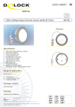
1
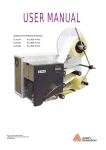
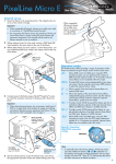
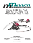
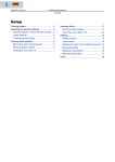
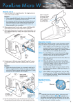
05/09 Rev. 5.02-01
USER MANUAL
DPM – PEM – ALX 92x
Maintenance & Cleaning
General Notice .............................................. 2
Maintenance by Qualified Personnel ........ 2
Safety ........................................................ 2
Troubleshooting ........................................ 2
Ordering Spare Parts ................................ 3
Note on Cleaning ...................................... 3
Cleaning Agents ........................................ 3
Printhead ....................................................... 5
General Notes ........................................... 5
Cleaning the printhead .............................. 6
Changing the print head ............................ 8
Checking the print head ............................ 9
Rubber rollers ............................................. 11
Feed / Print roller ..................................... 11
(PEM) Pressure roller .............................. 12
Deflection rollers ..........................................13
(DPM/ALX) Backing paper deflection
roller .........................................................13
(ALX) Material deflection rollers ...............13
Photoelectric switches .................................14
Cleaning the gap photoelectric switch .....14
Cleaning the material end photoelectric
switch .......................................................16
Cleaning the foil path ...................................17
Replacing the dust filter liner .......................18
DPM/PEM ................................................18
ALX ..........................................................19
(ALX 92x AI Pro) Fuse replacement ............20
2
05/09 Rev. 5.02-01
USER MANUAL
Maintenance & Cleaning
DPM – PEM – ALX 92x
General Notice
Maintenance by Qualified Personnel
Regular technical maintenance is required to ensure that the device is always
in operating order.
Qualifications
Maintenance work should only be carried out by qualified personnel. The safety, reliability and longevity of the device depend on correct maintenance.
¯ Persons causing damage as a result of unqualified maintenance, repair
and care are liable for these costs.
Manufacturer Service
For reliable maintenance, servicing, diagnosis and troubleshooting, please
contact your supplier, nearest dealer or another service supplier authorized by
the manufacturer.
Safety
WARNING!
Maintenance and cleaning may result in hazardous situations. Accidents
can occur by mechanical or electrical means if safety instructions are not observed!
« Turn off the device and disconnect the power cable prior to cleaning or
maintenance work!
ALX 92x AI Pro: Remove both power cables!
« On no account should liquid be allowed to enter the device!
« Do not use any of kind of spray directly on the printer! Moisten a cloth with
a cleaning agent to clean the device!
« Repairs to the printer may only be carried out by a trained service technician!
Troubleshooting
Status
If device malfunctions occur, analyze the device messages first. Please read
the relevant chapter contained in this documentation.
Calling for Service
If you are not authorized to carry out a diagnosis and repair of problems,
please call your technician or authorized service supplier. The service personnel have the required information and replacement parts to correctly carry out
the repairs.
3
05/09 Rev. 5.02-01
USER MANUAL
Maintenance & Cleaning
DPM – PEM – ALX 92x
Ordering Spare Parts
CAUTION! - Using parts that do not meet the manufacturer’s high standards
may damage the machine.
« Only use original spare parts supplied by the manufacturer.
The following information is required when ordering spare parts:
Order Specifications
• Model
• Device serial number
• Optional device configuration
• Description and part number of the spare part
• Number of parts required
Note on Cleaning
Frequency of Care
Frequent maintenance and cleaning is required to ensure that the device operates safely and provides a high level of performance. The frequency with
which maintenance checks are required depends on operating and environmental conditions, the length of operation daily, and the print media used.
¯ In particular, the printhead and feed roller need to be checked regularly for
paper, adhesives and ink residues.
Cleaning Agents
Dirty component
Printhead
Print roller and other rubber
rollers
Metal deflection axis or
-guide tube
Cleaning agent
Order number
Printhead Cleaning pen [1A] 95327
Cleaning paper
5030
Roller cleaner [1B]
98925
Cleaning fuel
Label remover
Plastic deflection rollers
(ALX 92x)
Cleaning fuel
External parts
Common neutral cleaning liquid
90073
[Tab. 1] Recommended cleaning agents.
CAUTION! - Keep to the following rules to avoid damaging the device:
« Do not use any cleaning agent that could damage or destroy the resin
surface, labelling, display, nameplates, electrical components, etc.
« Do not use any cleaning agents that are abrasive or damaging to plastics.
Avoid acid or alkaline solutions.
4
05/09 Rev. 5.02-01
USER MANUAL
DPM – PEM – ALX 92x
B
A
[1]
Printhead cleaning pen (A) and roller cleaner (B).
Maintenance & Cleaning
5
05/09 Rev. 5.02-01
USER MANUAL
Maintenance & Cleaning
DPM – PEM – ALX 92x
Printhead
General Notes
The unit consisting of the thermal head [2A]
and thermal head holder [2C] will henceforth be
referred to as the printhead [1].
CAUTION! - The position of the
thermal head on the thermal head
holder is set at the factory with optical
aids.
« For this reason, always completely
replace misaligned printheads and if
necessary send them in for resetting.
[1]
Printhead
C
CAUTION! - Electrostatic discharges
or contact with sharps edges can
damage the printhead.
« Protect the printhead from
electrostatic discharges when
performing maintenance work or
cleaning.
B
A
« Avoid touching the thermal edge
[2B] printhead with bare hands as
much as possible.
« Do not allow sharp objects to
come into contact with the termal
edge.
If you do not have any professional ESD protection equipment (ESD wristband, ESD shoes,
…), place one hand on an earthed object near
to you (e.g. tap or radiator) before touching the
device to discharge any static charge your body
may be carrying.
[2]
Printhead side view
A Thermal head
B Thermal edge
C Thermal head holder
6
05/09 Rev. 5.02-01
USER MANUAL
Maintenance & Cleaning
DPM – PEM – ALX 92x
Cleaning the printhead
WARNING! - During operation, the
printhead can become hot.
A
« Care should be taken when touching the printhead!
A
Impurities such as lint and colour particles from
the thermal transfer ribbon may collect on the
printhead during printing. This can degrade the
printed image considerably. Noticeable effects:
• Differing contrast on the labels
• Light stripes in the printing direction
¯ Clean the printhead and the print roller reg-
[3]
ularly, and always clean them before inserting
a new ribbon. When using direct thermal mode,
always clean them before inserting a new material roll.
Printhead of a PEM-06.
A Thumb screws
A
Cleaning the print roller: See chapter Rubber
rollers on page 11.
Preparing the printhead
1. Switch off the device.
2. Pull out the mains plug.
3. Remove material and ribbon.
4. Unscrew the two wing screws [3A], until the
printhead can be swivelled upwards.
[4]
Cleaning the printhead with a cleaning pen.
A Thermal edge
¯ Before swivelling the printhead upwards, shift it approx. 1 cm to the middle of
the axle.
¯ Mark the printhead position on the axle,
before moving it.
Cleaning with a cleaning pen
« Run the pen over the thermal transfer head
a few times.
A
Cleaning with a cleaning stripe
« Use the rough side of the cleaning strip [5A]
to wipe a few times along the thermal edge.
Press the stripe slightly to the thermal edge,
while doing so.
[5]
Druckkopf reinigen mit dem Reinigungsstreifen.
7
05/09 Rev. 5.02-01
USER MANUAL
Maintenance & Cleaning
DPM – PEM – ALX 92x
Cleaning with alcohol-based solvents
WARNING!
Solvents are highly flammable.
« Always comply with the safety
guidelines for using flammable liquids.
« Do not smoke while servicing the
device.
1. Moisten a lint-free cloth with solvent and
wipe the thermal transfer printhead with it.
2. After cleaning, return the print head mounting to its old position and retighten the
thumb screws.
¯ Press the thumb screw on the tapered
edge of the square axle and ensure the exact positioning of the print head mounting
on the axle.
¯ Pay attention to the position of the print
head in relation to the edge of the label.
Factory set printhead position: Flush
against the inner black plastic plug.
3. Before switching on the device, check
whether the printhead cable is still properly
connected. If this is not the case, plug in the
cable correctly.
[6]
Cleaning the printhead with an alcohol-based solvent.
8
05/09 Rev. 5.02-01
USER MANUAL
Maintenance & Cleaning
DPM – PEM – ALX 92x
Changing the print head
The printhead can only be replaced completely
as illustrated [7].
WARNING! - During operation, the
printhead can become hot.
« Care should be taken when touching the printhead!
1. Switch off the device.
2. Pull out the mains plug.
3. Remove material and ribbon.
[7]
Complete printhead.
[8]
Remove both cables from the printhead (Fig.: DPM).
4. Pull out both plugs from the printhead [8].
¯ Wait at least 3 minutes after switching
off the device before removing the print
head cable from the print head. Mark the
position of an axially adjusted print head.
5. Unscrew both wing screws on the printhead
until the printhead can be removed from the
contact shaft [9].
6. To install, move the new printhead to the old
position and tighten the wing screws.
Printhead factory setting: Flush against the
inner black plastic plug.
¯ Before doing this make a note of the resistance value of the print head (read off
from the print head). When placing the print
head on the print head mounting, ensure
that the print head is lying flat.
A
¯ The wing screws must press on the tapered edge of the square axle.
¯
Pay attention to the position of the print
head in relation to the edge of the label.
7. Plug the printhead cable back into the print
head.
[9]
Remove the wing screws (A) and remove the printhead
(Fig.: DPM)
9
05/09 Rev. 5.02-01
USER MANUAL
Maintenance & Cleaning
DPM – PEM – ALX 92x
8. The resistance value of every new print
head must be entered after putting the printer into operation. Use the parameter
SYSTEM PARAMETERS > Head resistance.
¯ The resistance value can be found on a
label on the printhead [10 circle].
CAUTION!
Entering a false resistance can
damage the printhead!
For additional information refer to the service
manual, topic section „Service Mechanics“,
chapter Replacing the printhead on page 68.
[10] The printhead resistance can be found on a label on the
printhead itself.
Checking the print head
Both, DPM/PEM and ALX 92x are equipped
with a test function, which tests the functionality
of every single dot (dot check).
There are two different modes of operation with
three different possibilities to start a dot check:
Dot check modes
Automatic dot check
Call by
Automatic execution after powering on or in printing pauses. To activate
the automatic, refer to parameter SYSTEM PARAMETERS > Autom. dot check
Easy Plug: Add an optional D to the obligatory #ER command (-> #ERD)
to trigger a dot check at the end of the print job.
Dot check with subsequent status report that informs about the number
and the location of the defective dots. Parameter .SERVICE FUNCTIONS >
Head dot test.
Dot check on demand
Dot check with subsequent printing of a pattern which visualizes the test
result. Parameter PRINT INFO > Dottest punched.
In Off-line mode by pressing the Apply+Feed buttons. Equals the call by
parameter „Head dot test“, but without the status report. Defective dots are
displayed by status messages.
[Tab. 1] Starting a dot check.
10
05/09 Rev. 5.02-01
USER MANUAL
DPM – PEM – ALX 92x
Display message
Display of a detected defective dot:
Status:
5103
Dot defective
If all dots are faultless, no display message appears.
If the status message appears, the current print
job is stopped.
Duration
All five ways of dot checking test the entire
printhead width. Therefore, the test procedure
may take from 10 s up to several minutes time
(the wider the printhead is and the more dots
are defective, the longer).
CAUTION! - Disregard of the
following may cause the printer
firmware to hang up:
« Never change the setting of a dot
check parameter, during a dot check
is running!
Abortion
¯ Only if it really cannot be avoided,
cancel
the dot check by a reset (press Feed+Cut+Online button)!
CAUTION! - Disregard of the following
can destroy single dots of the print
head:
« Never cancel a dot test by
switching off the printer!
Maintenance & Cleaning
11
05/09 Rev. 5.02-01
USER MANUAL
Maintenance & Cleaning
DPM – PEM – ALX 92x
Rubber rollers
A
B
C
Feed / Print roller
All rubber rollers contained in the DPM/PEM
and in the ALX 92x can be cleaned from the
bottom side of the machine without any disassembly. The ribbon roller is easily accessible by
opening the hood and removing the ribbon.
1. Switch off the device.
2. Pull out the mains plug.
3. Remove material and/or ribbon.
4. Clean the print roller with a dust-free cloth
and roller cleaner.
[11] DPM/ALX 92x: Print- (A), brake- (B) and feed roller (C) are
accessible from the devices bottom side.
CAUTION! - Disregarding the
following may damage the roller:
« Never use knives or sharp-edged
objects to clean the rollers!
¯ To access the print roller from the front side,
the printhead can be disassembled:
Refer to chapter Changing the print head on
page 8 to learn how to do this.
A
B
[12] PEM: Print- (A) and feed roller (B) looked at from the bottom
side.
12
05/09 Rev. 5.02-01
USER MANUAL
Maintenance & Cleaning
DPM – PEM – ALX 92x
(PEM) Pressure roller
WARNING! - During operation, the
printhead can become hot.
« Care should be taken when touching the printhead!
A
1. Switch off the device.
2. Pull out the mains plug.
[13] Fixing screw (B) of the guiding section
3. Remove material.
4. Remove screw [13A] (use a 3 mm allen
key).
5. Remove the guiding section [14A] to the
side.
6. If the printhead is neither positioned completely to the right nor the left, mark the position of the printhead on the axle.
7. Loosen both wing screws [15A] at the printhead.
A
8. Remove the printhead [15] from the axle.
9. Moisten a dust-free cloth with roller cleaner
(part no. 98925) and wipe the pressure roller with it. Gradually rotate the roller until it is
completely clean.
[14] Guiding section (A)
10. Remount the printhead into its former position.
11. Reassemble the guiding section and fix it
with the screw.
A
B
¯ Make sure to feed the right one of the
two guiding noses [16A] into the groove at
the guiding section.
A
[15] Printhead removed from the printhead axle
A Wing screws
B Pressure roller
A
[16] Guiding noses (A) at the photoelectric switch fork
13
05/09 Rev. 5.02-01
USER MANUAL
Maintenance & Cleaning
DPM – PEM – ALX 92x
Deflection rollers
(DPM/ALX) Backing paper
deflection roller
Clean the material deflection roller, if it is dirty
with residues of adhesive, labels or something
similar.
A
C
1. Switch off the device.
2. Pull out the mains plug.
B
3. Remove material.
4. Screw out the thumb screw [17B] and take
off the locking plate [17C].
5. Pull the deflecting roller [18A] off its axle.
[17] Backing paper deflection roller at the DPMs printing module
A Deflection roller
B Thumb screw
C Locking plate
6. Clean the deflecting roller using cleaning
fuel or adhesive removing solvent, depending on the degree of pollution.
7. Put the deflecting roller back on the axle;
apply locking plate and thumb screw.
A
[18] Pull off the deflection roller (A).
All of the material deflection rollers [19A] at the
ALX 92x should be cleaned regularly in order to
not disturb material feeding and with it the printing quality.
« Wipe the rollers with a clean cloth and
cleaning fuel.
Z0189.cdr
(ALX) Material deflection rollers
A
A
[19] Material deflection rollers (A) at the ALX 92x.
14
05/09 Rev. 5.02-01
USER MANUAL
Maintenance & Cleaning
DPM – PEM – ALX 92x
Photoelectric switches
The photoelectric switches must be cleaned of
material and dust particles at regular intervals
depending on the materials used.
Cleaning the gap photoelectric
switch
A
Dismantle the guiding section first, to get proper access to the gap photoelectric switch:
1. Switch off the device.
2. Pull out the mains plug.
3. Remove material.
[20] Mounting bolts (A) of the guiding section (Fig.: DPM).
4. Unscrew both screws [20A] (using a 3 mm
allen key).
¯ At the PEM, there is only one fixing
screw to remove.
B
5. Slide out the guiding section [21B] to the
side.
Continued overleaf.
[21] Sliding out the guiding section (B) (Fig.: DPM).
15
05/09 Rev. 5.02-01
USER MANUAL
Maintenance & Cleaning
DPM – PEM – ALX 92x
6. Clean the gap photoelectric switch with
compressed air (compressed air can be ordered in a can as an accessory) [22].
¯ Additionally clean it using cleaning fuel
and a dust-free cloth if it is particularly dirty.
[22] Blow compressed air at this point (arrow) to clean the photoelectric switch.
7. Assembly: Feed the right one of the two cylindrical shapes [24B] into the groove at the
guiding profile. Both steel pins [23A] must fit
into the holes [24A]! Replace the screws
and tighten them.
A
[23] Guiding section disassembled.
A Steel pins
A
B
[24] Printmodule DPM
A Holes, into which the steel pins must fit (Fig.: DPM).
B Cylindrical shapes at the gap photoelectric switch.
16
05/09 Rev. 5.02-01
USER MANUAL
Maintenance & Cleaning
DPM – PEM – ALX 92x
Cleaning the material end photoelectric switch
The material end photoelectric switch [25A] is
located on the inner red material feed on the
print module. It is necessary to regularly clean
the photoelectric switch of material and dust
particles. The cleaning intervals are dependent
on the materials being used.
A
« Clean the material end photoelectric switch
with compressed air (compressed air can be ordered in a can as an accessory).
¯ Additionally clean it using cleaning fuel and
a dust-free cloth if it is particularly dirty.
[25] Material end photoelectric switch (A) on the inner material
feed.
17
05/09 Rev. 5.02-01
USER MANUAL
Maintenance & Cleaning
DPM – PEM – ALX 92x
Cleaning the foil path
Parts, which contact the foil, must be cleaned
regularly. The following intervals should be
considered:
• weekly
or
A
• after 5000 m of foil
B
C
D
[26] Parts, which may be soiled with foil residue:
A Ribbon roller
B Deflection roller + stress relief
C Deflectioin axle
D Deflection nose at the printhead
18
05/09 Rev. 5.02-01
USER MANUAL
Maintenance & Cleaning
DPM – PEM – ALX 92x
Replacing the dust filter
liner
CAUTION! - An exhausted filter liner
can cause the power supply to
overheat and the device to break
down.
« Replace the filter liner regularly,
at least in monthly intervals.
DPM/PEM
Tool: Medium size philips screwdriver.
1. Remove the screws [27A] and the filter
housing [27B].
A
B
[27] Dust filter at the DPM/PEM (B).
2. Replace the liner [28A] (part number for one
liner: A2236).
3. Remount the filter housing.
A
[28] Filter liner (A).
19
05/09 Rev. 5.02-01
USER MANUAL
Maintenance & Cleaning
DPM – PEM – ALX 92x
ALX
¯ The dust filter is an optional accessory.
Tool: Screwdriver.
1. Turn the screw [29A] by a quarter-turn. Remove the cover [29B].
2. Replace the liner (part number for 5 liners:
A2581).
3. Reassemble the filter housing cover. Turn
the screw [29A] by a quarter-turn.
B
[29] Dust filter at the ALX 92x
[30] Filter housing removed.
A
20
05/09 Rev. 5.02-01
USER MANUAL
Maintenance & Cleaning
DPM – PEM – ALX 92x
(ALX 92x AI Pro) Fuse
replacement
Tool: Screwdriver, medium size
Fuse type: T2AH/250 V
(Article number: A8676)
A
WARNING!
The device operates using mains
voltage! Touching electrically live
parts may expose you to hazardous
electrical currents and may lead to
burns.
The device can only be completely
disconnected by unplugging both
power cables.
[31] Fuse insert at power connector „Mains 2“.
« Switch off the device and unplug
both power cables before removing
the fuse insert.
1. Switch off the device. Remove both power
plugs.
2. Remove the fuse insert [31A] to the left of
the power connector.
A
3. Remove the fuse [32A] from the insert and
replace it by a new one.
[32] Fuse insert removed.