1
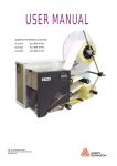
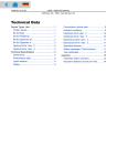
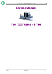
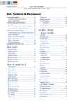
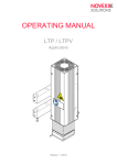
06/06 Rev. 3.05-01 OPERATING MANUAL ALX 92x Setup Winding pattern ............................................. 2 Selecting the printing material ....................... 4 Thermal transfer / direct thermal printing .. 4 Label material ............................................ 4 Thermal transfer ribbon ............................. 5 Inserting label material .................................. 6 Removing spent backing paper ................. 6 Removing glue residue ............................. 6 Inserting a new label roll ........................... 7 Inserting ribbon ............................................11 Removing spent ribbon ............................11 Inserting a new ribbon roll ........................12 Settings .......................................................13 Ribbon tension .........................................13 Label sensor ............................................14 Adjustment button for printhead pressure 15 Dispensing edge ......................................16 Dispenser parameters .............................16 Material Parameters ................................17 Index ............................................................18 2 06/06 Rev. 3.05-01 OPERATING MANUAL Setup ALX 92x Winding pattern The winding diagram shows the winding direction of material and ribbon through the ALX 92x. « Follow this basic scheme when inserting/changing material and ribbon. ¯Only specially trained staff to insert and change the ribbons and material. 8 Z0189.cdr 7 1 2 3 4 5 6 24 23 22 9 15 21 20 19 18 17 16 14 13 12 11 5 [1] 10 Material and ribbon path in the ALX 92x (left version). 3 06/06 Rev. 3.05-01 OPERATING MANUAL Setup ALX 92x Names of parts No. Name No. Name 1 Adjustment knob for printhead 13 pressure Feed roller 2 Ribbon rewinding mandrel 14 Deflection roll 3 Ribbon unwinding mandrel 15 Material guide 4 Operation panel 16 Opener 5 Deflection roll 17 Brake roller 6 Material dancer arm 18 Adjustment wheel for label sensor 7 Material unwinder 19 Print roller 8 Guiding rod 20 Dispensing edge 9 Backing paper rewinder 21 Printhead 10 Backing paper dancer arm 22 Ribbon deflection axle 11 Pressure roller 23 Ribbon deflection roller with stress relief 12 Lever for pressure roller 24 Ribbon roller [Tab. 1] ALX 92x operating parts 4 06/06 Rev. 3.05-01 OPERATING MANUAL Setup ALX 92x Selecting the printing material Thermal transfer / direct thermal printing The ALX 92x can print onto label material using the direct thermal mode or thermal transfer mode. Direct thermal Direct thermal printing is done without ribbon. The direct thermal process requires label material with a temperature-sensitive coating. The printout is produced by applying precise bursts of heat to the material under the printhead. This changes the colour of the coating. Thermal transfer Thermal transfer printing is done with (thermal transfer) ribbon on “normal” label material. The printout is produced by applying precise bursts of heat to the thermal transfer ribbon under the printhead. This transfers the colour particles to the label. Label material The ALX 92x was developed for printing on self-adhesive stock. Pay attention to the following factors when selecting label material: • • • The roughness of the material surface The printhead temperature required for the colour transfer Size of the material roll. The following dimensions need to be checked: Outside-/inside diameter of the material roll and the material width Material roughness If the material is very rough, the printhead will be worn down more quickly than when using a smooth material. This is an important aspect of thermal printing. With thermal transfer printing, this doesn’t pose such a problem, because you can – and indeed should – select a ribbon that is wider than the material. This means that the printhead is protected over the entire width of the material. Printhead temperature High printhead temperatures can similarly cause problems. The material and the ribbon take longer to cool. As a result, the print quality may degrade – particularly at high print speeds. The printhead also wears down more quickly. ¯The printing result is highly dependent on the right combination of label material and thermal transfer ribbon. The surface of the label material determines which thermal transfer ribbons produces the best adhesion. Unsuitable ribbons can lead to poor printing results. P Further information can be found in the topic section Technical data, section “Label material”. 5 06/06 Rev. 3.05-01 OPERATING MANUAL Setup ALX 92x Thermal transfer ribbon The following is recommended for thermal transfer ribbons: • • • • The back of the ribbon should be coated so that it produces no static or friction (Backcoating). If this isn’t the case, the printhead may be damaged by static discharge coming off the ribbon surface. The ribbons need to be designed for “corner edge” printheads. Ribbons should be able to handle print speeds of up to 400 mm/s (16 ips). Size of the ribbon roll: The following dimensions need to be checked: outside/ inside diameter of the ribbon roll, ribbon width. CAUTION! - Thermal transfer ribbons without these properties can degrade the performance of the printer and the print quality as well as damage the printhead! Armor APR 600 (Avery part no. 2240-600-xxx) is a recommended ribbon type. ¯The thermal transfer ribbon should only be slightly wider than the label material. • • If an overly narrow ribbon is used, the border of the label material interferes with the printhead – which wears it down more quickly. If an overly wide ribbon is used, creasing may occur in the ribbon. This can led to poor printing results. P For more details on the permissible dimensions of ribbon rolls, refer to Technical data, “Thermal Transfer Ribbon”. 6 06/06 Rev. 3.05-01 OPERATING MANUAL Setup ALX 92x Inserting label material WARNING! Rotating parts can trap items and draw them in! « When working on the device, do not wear loose jewellery, long sleeves, long hair, and similar. « Close the devices cover before printing. • • During operation, the printhead can become hot. « Be careful when touching the printhead! A [1] Rewound backing paper on the ALX 92x (A). Removing spent backing paper The backing paper rewinder can exactly rewind the amount of backing paper remaining from a material roll with 300 mm diameter [2A]. B CAUTION! - A backing paper roll exceeding the diameter limit can stall and damage the machine! « Always remove the backing paper from the rewinder if you insert a new material roll! A [2] Assuming backing paper has gathered on the rewinder: 1. Pull out the release button [2B]. The tensioning mechanism of the rewinder is slackened. 2. Remove the rewound backing paper. Removing glue residue « If necessary, clean the following components: • Printhead • Dispensing plate • Deflection rollers • Drive roller • Pressure rollers P Follow the directions provided in topic sec- tion Maintenance and Cleaning. Removing rewound backing paper. A Backing paper roll B Release button 7 06/06 Rev. 3.05-01 OPERATING MANUAL Setup ALX 92x Inserting a new label roll B 1. Turn thumb screw [3A] loose and swivel guide rod [3B] aside. 2. Push the material roll onto the unwinder [3C] with the appropriate adapter rings. The material roll should turn in an anticlockwise direction when unwinding. C A 3. Swivel guide rod to the unwinder axle as illustrated [3] and shift it close to the material roll. Tighten the thumb screw again. [3] 4. Lay the material around deflection rollers [4A] and dancer arm [4B]. P Continued overleaf ALX 92x with half used up label roll. A A [4] B Threading the label material around deflection rollers (A) and dancer arm (B). 8 06/06 Rev. 3.05-01 OPERATING MANUAL Setup ALX 92x 5. Open the front cover. 6. Set the material guide to the width of the label material. To do this loosen the thumb screw [5A] at the front material guide, shift the material guide [5B] crossways to the feed direction and tighten thumb screw again. A ¯ The label material should slide easily between the material guides. B [5] Adjusting the material guide (B). 7. Press the opener [6A] to raise the contact rollers [6B]. Push the beginning of the label material through underneath the contact rollers and the print head. B A [6] Inserting the label material at the print module. [7] Positioning the contact rollers. 8. Position the contact rollers while pressing down the opener [7]. ¯ Both contact rollers should press down the material symmetrically. P Continued overleaf 9 06/06 Rev. 3.05-01 OPERATING MANUAL Setup ALX 92x 9. Peel labels off the backing paper for a stretch of appr. 50 cm [8]. [8] Peeling some labels off . 10. Open the pressure roller lever [9A] by pressing it downwards. 11. Pull the backing paper backwards underneath the printing module and insert it as illustrated [9]. A [9] 12. ALX 925/926: Loosen the two thumb screws [10B] at the spring-suspended blocks. Position the spring-suspended blocks [10A] in a way that the contact rolls press symmetrically on the backing paper. Retighten the thumb screws. ALX 924: Loosen the thumb screw [10B]. Position the spring-suspended block [10A] in a way that the contact roll presses in the middle on the backing paper. Retighten the thumb screw. Threading the backing paper underneath the printing module. B A [10] Spring-suspended block (A) at a ALX 924. 13. Tighten the backing paper backwards and close the lever [11]. [11] Closing the pessure roller lever. 10 06/06 Rev. 3.05-01 OPERATING MANUAL Setup ALX 92x 14. Thread the backing paper around dancer arm [12A] and deflection roller as illustrated [12]. 15. Pull out the release button [12B]. B A [12] Threading the backing paper around the tensioning arm (A). 16. Insert the end of the backing paper into the rewinder as illustrated [13]. 17. Push in the locking knob. [13] Threading the backing paper around the rewinder. 18. Turn the rewinder manually anti-clockwise until the backing paper is tightened [14]. [14] Tightening the backing paper. 11 06/06 Rev. 3.05-01 OPERATING MANUAL Setup ALX 92x Inserting ribbon WARNING! • Rotating parts can trap items and draw them in! « When working on the printer, do not wear loose jewellery, long sleeves, long hair, and similar. « Close the devices cover before printing. • During operation, the printhead can become hot. « Be careful when touching the printhead! ¯ Skip this section if you intend to print directly onto thermal material. P For information on choosing a suitable thermal transfer ribbon, refer to section Selecting the printing material on page 4. Removing spent ribbon CAUTION! - If the diameter of the ribbon wound on the take-up roll becomes too great, the machine’s operation will be impaired. « Always remove a used ribbon before inserting a new ribbon roll. Assuming spent ribbon has gathered on the rewinding mandrel: 1. Remove the roll of used ribbon from the rewinding mandrel. 2. Pull the empty ribbon core off the unwinding mandrel and put it on the rewinding mandrel. 3. Put the ribbon roll on the unwinding mandrel. 4. Insert the ribbon as described in the following. 12 06/06 Rev. 3.05-01 OPERATING MANUAL Setup ALX 92x Inserting a new ribbon roll 1. Open the hood. 2. Put the ribbon roll on the lower right ribbon mandrel [15C]. Put an empty take-up roll on the upper left ribbon mandrel. B ¯ The ribbon must unwind anti-clockwise. (Only valid for ribbon rolls which have the coloured side facing inwards) 3. Guide the ribbon end under the ribbon deflection [15B] and thread through to the side of the printhead [15A]. A C [15] Inserting the ribbon roll onto the ribbon unwinding mandrel (C). 4. Pull the ribbon under the printhead from the side, then, unwinding some ribbon, smoothen it out [16]. [16] Smoothening out the ribbon. 5. Draw ribbon upwards and guide it around the ribbon roller [17A], the ribbon deflection roller [17B] and the strain relief [17C] . A 6. Attach the ribbon end to the empty take-up roll. Winding direction: clockwise [18A]. B C A [18] Winding direction of ribbon rewinding mandrel (A) [17] A Ribbon roller B Ribbon deflection roll C Strain relief 13 06/06 Rev. 3.05-01 OPERATING MANUAL Setup ALX 92x Settings Ribbon tension To achieve an optimal print result, the ribbon has to run without creases. This is achieved by correctly setting the torque for the rewinding mandrel and the braking torque for the unwinding mandrel. The factory settings cover a wide range of different ribbon widths. Nevertheless, adjustment can be necessary if very narrow or very wide ribbons are being used. The braking torque of the ribbon mandrels can be set by adjusting the red hexagonal plastic nuts [19A] on the ribbon mandrels. Turn clockwise to increase the torque. Caps [19B] protect the nuts against being adjusted by accident. The ribbon must run evenly and free of creases between the mandrels while being fed through. The following indications can help you correct the settings: • The ribbon is slack or in folds or winds on to the rewinding mandrel too loosely. « Increase torque / braking torque (turn red hex nut clockwise). • The ribbon clearly stretches or it tears during printing. The ribbon is not being transported adequately. « Decrease torque / braking torque (turn red hex nut anti-clockwise). A B [19] Ribbon mandrels on a ALX 92x. A Ribbon rewinding mandrel (without cap) B Ribbon unwinding mandrel (without cap) 14 06/06 Rev. 3.05-01 OPERATING MANUAL Setup ALX 92x Label sensor The ALX 92x is equipped with a light transmission sensor for punch recognition: Setting the label sensor Turning the red adjustment wheel [20B] moves the sensor up to 80 mm (4“/5“ modules) or 100 mm (6“ modules) across the material. A dial [20A] displays the value. Reading the value: Value = punch position – 2 mm A … whereby the following applies: • Punch position: Distance of the punch from the (inner) edge of the material [21A]. • Value: Value on dial, set by rotating the red wheel. B [20] Setting the label sensor A Dial B Adjustment wheel Example: Punch centre = 11 mm from the left edge; subtracting 2 mm gives a value of 9 mm. « To make the setting, turn the wheel [20B] until the desired value is aligned with the mark [20A]. ¯ Round labels: To ensure in those cases, that the label start is correctly identified, a punch offset can be preset. This may be done by manually setting the printer (Parameter PRINT PARAMETERS > X - print offset) or by the appropriate control command. A [21] Measuring the punch position (A). 15 06/06 Rev. 3.05-01 OPERATING MANUAL Setup ALX 92x Adjustment button for printhead pressure The material width and / or material thickness influence the pressure applied by the thermal transfer printhead on the print roller. There are three possible settings for pressure [23]: I Setting for thin / narrow material II Setting for material of medium width / thickness III Setting for thick / broad material Setting The red adjustment knob [22A] [23] is located above the ribbon roller in the front plate and can be adjusted with a coin or large screwdriver. A « To set medium pressure, turn the arrow [23A] to position „II“ until it slots gently into place. « To set a higher pressure, turn the arrow to position „III“ until it slots gently into place. CAUTION! - Failure to set for the correct pressure causes the printhead to wear down more quickly and leads thus to a shorter service life. « Always select the lightest possible pressure necessary to produce an acceptable print result. [22] A Adjustment knob for the printhead pressure A « Excessive pressure can lead to the premature wearout of the printhead. Factory settings Setting „I“, for thin / narrow material [23] A Adjustment knob for the printhead pressure 16 06/06 Rev. 3.05-01 OPERATING MANUAL Setup ALX 92x Dispensing edge By inclining the dispensing edge, the dispensing position can be fine adjusted without having to change the machine position: 1. Undo the screws [24B] on both of the side mounting plates. Access the screws from beneath. Tool: 2.5 mm Allen key 2. Turn the dispensing edge [24A] to the desired position. 3. Tighten the screws. A B [24] Long dispensing edge (option) (feed roller disassembled for better viewing). Dispenser parameters Set the following parameters prior to first operating the machine. • PRINT PARAMETERS > Dispense Mode Determines sequence of the printerdispenser process (normal 1:1 mode, batch mode or true 1:1 mode) PRINT PARAMETERS > Dispenseposition Setting the adhesive edge, with which the label after dispensing adheres to the backing paper[25]. • SYSTEM PARAMETER > Start source Setting the trigger signal source for the printer-dispenser process (foot switch, sensor or USI) P For details on how to set parameters, refer to Information on printouts and parameters in the “Using the Parameter Menu” section. Dispensed label Dispense position Dispensing edge Backing paper Z0040E.cdr • [25] Dispensing position (=home position) shown schematically. 17 06/06 Rev. 3.05-01 OPERATING MANUAL ALX 92x Material Parameters Using the following parameters, you can tell the device which kind of labelling material is supposed to be processed: • PRINT PARAMETERS > Material type Sets material type (punched or endless). • PRINT PARAMETERS > Material length Sets material length (measured from label start to label start, that is label length plus one gap length). Setting not relevant for endless material. • PRINT PARAMETERS > Material width Sets material width. P For details on how to set parameters, refer to Information on printouts and parameters in the “Using the Parameter Menu” section. Setup 18 06/06 Rev. 3.05-01 OPERATING MANUAL ALX 92x Index B R Backcoating 5 Braking torque, ribbon 13 Ribbon mandrels 13 Ribbon slack 13 Ribbon tears 13 Ribbon tension 13 D Direct thermal printing 4 S H Setting material parameters 17 Setting the dispenser parameters 16 Setting the label sensor 14 Setting the printhead pressure 15 Hexagonal plastic bolt, red 13 I Inserting ribbon 11 L Label material 4 Label sensor, setting 14 T Thermal transfer printing 4 Torque, ribbon 13 W Wheel for setting label sensor 14 Winding diagram 2 Setup 02/13 Rev. 5.08-01 OPERATING MANUAL ALX 92x Device description, Operation Device description ......................................... 2 Operating Parts ......................................... 2 Connections .............................................. 5 Warning notices ........................................ 7 Operator panel .......................................... 8 Operating modes ..................................... 10 Basic operating procedures ........................ 12 Connecting the device ............................. 12 Setting the interface ................................ 13 Offline operation ...................................... 14 Online operation ...................................... 15 Creating a print job .................................. 15 Transferring a print job ............................ 16 Applying memory cards ........................... 17 Setting the realtime clock ........................ 18 Reading out the realtime clock value using Easy Plug ................................................ 18 The first device test ..................................... 19 Settings for the material type .................. 19 Printing the status report ......................... 19 2 02/13 Rev. 5.08-01 OPERATING MANUAL Device Description ALX 92x Device description Operating Parts C B A D E F H J G I [1] Exterior of the ALX 92x. A Pre-drilled holes for assembling the applicator Assembly of the pivot unit for the applicators LTSI, LTP or LTPV B Operator panel LCD display; 5 operating keys; on / off button; displays the device operating status; for defining settings in the parameter menu C Material unwinder Unwinds the label material D Guiding rod Prevents rolls from slipping off the material unwinder and the backing paper rewinder E Material dancer arm Compensates abrupt movements of the label web F Backing paper rewinder Rewinds the remaining backing paper 3 02/13 Rev. 5.08-01 OPERATING MANUAL ALX 92x G Backing paper dancer arm Compensates abrupt movements of the backing paper web H Window For checking the ribbon supply without opening the front cover I Front hood Open up to insert ribbon J Printhead Device Description 4 02/13 Rev. 5.08-01 OPERATING MANUAL Device Description ALX 92x A B C D E [2] F ALX 92x operating parts A Insert diagram Shows the path of the labelling material and ribbon B Ribbon unwinding mandrel Holds the new ribbon roll C Ribbon rewinding mandrel Holds the ribbon core onto which used ribbon is wound D Adjustment knob for printhead pressure For adjusting the printhead pressure to suit the material strength / width E Adjustment wheel for label sensor Turning the wheel moves the label sensor at right angles across the material path F Material guide Guides the material path from both sides; the material end sensor is located on the inner side 5 02/13 Rev. 5.08-01 OPERATING MANUAL Device Description ALX 92x Connections CAUTION! - Additional devices of inadequate quality can damage the device! Connect the device only to devices that fulfil SELV (safety extra-low voltage) circuit requirements acc. to EN 60950! Only connect OEM accessories. G H G H I J K A B L B L M N C I J K M O P P D Q E D E F [3] Connections at the ALX 92x (RH). Left: ALX 92x with the options Applicator Interface (B), Signal Interface (Q), OD-sensor (O), 2nd card slot (N), external operator panel (A). Right: ALX 92x AI Pro with the option Applicator Interface (B). A (Option) Mini-DIN connector To connect an external operator panel B (Option) Applicator Interface (AI) For controlling nearly arbitrary applicator types C (Future Option) Connection Rotary Encoder – For automatic speed adaption – Is not yet supported D Power switch Turns the device on/off. An additional switch is located on the operator panel E Power socket Mains connection of the machine F (ALX 92x AI Pro only) Power socket Mains connection of the Applicator Interface „AI Pro“. 6 02/13 Rev. 5.08-01 OPERATING MANUAL Device Description ALX 92x G Ethernet interface To connect to an „Ethernet 10/100 Base T“ network H Status-LED/Ethernet I RS232 interface For serial transfer of print data J Centronics interface For parallel transfer of print data (cable is inclusive) K 2x USB interface type B (device) To connect devices (e.g. keyboard, scanner) L USB interface type A (host) For transfer of print data M Card slot For CompactFlash cards; used for storing fonts, logos, graphics, etc. N (Option) Second card slot O (Option) Cable duct for OD control To connect a photoelectric barrier, which checks the outer diameter of the label material roll P Card slot – For SD/MMC cards – Is not yet supported Q (Option) Signal interface USI – 4 inputs / 8 outputs – 24 V signal voltage 7 02/13 Rev. 5.08-01 OPERATING MANUAL Device Description ALX 92x Warning notices ! WARNING Keep hands clear of rollers. A5346 [4] Warning notice on the ALX 92x The label depicted at [4] warns against the danger of being caught in the moving parts of the device. Warning labels must be replaced if they are lost or become illegible (part nr. A5346). 8 02/13 Rev. 5.08-01 OPERATING MANUAL Device Description ALX 92x Operator panel A B C D E F G H [5] Operator panel at an ALX 92x Power indicator [5A] Lights up green, when the device is switched on. Error indicator [5B] Lights up red, when the device is in message mode. Display [5D] With 32 digits and two lines, the display shows the operating conditions (modes) for parameters, values, status and errors. You can select the language you want to use for the display. Backlighting ensures good legibility. Button functions The buttons offer a multitude of operating functions. A logical menu structure is used for operation. The meaning of each button varies according to the operating mode and the menu item. Additionally, special functions have been programmed for certain button combinations. Depending on the modes and menu levels, the following functions apply for each button: On/Off button Online button [5C] Switches the device on or off. To reach this, hold the button longer than 2 seconds pressed. Precondition: The mains switch must be switched on (position „I“, see Connections on page 5). • See [5G] • For switching between online and offline mode. • For confirming entries, menu items and messages. • For selecting print jobs and for entering values in standalone mode. Apply button • See [5H] • Triggers the application process. Requirements: – Applicator fitted and activated – Device offline. • Also for accessing deeper levels within the menu structure and selecting menu items. • For decrementing values. 9 02/13 Rev. 5.08-01 OPERATING MANUAL Device Description ALX 92x Feed button • See [5F] • For feeding in material when the device is offline. • For starting the printing process once the feed has been stopped (in online mode). • Also for accessing deeper levels within the menu structure and selecting menu items. • Increments values. Prog button • See [5E] • For accessing the parameter menu when offline. • For stepping back through the parameter menu and/or exiting it. • For more detailed descriptions of the button functions, see – Offline operation on page 14 and Online operation on page 15 – Topic section Info-Printouts and Parameters Remote operator panel ALX 92x Gen. 3 (or higher) machines can be equipped with a remote operator panel. For this, the machine must provide the appropriate - optional - connector, see Connections on page 5. The connection can be retrofitted (see service manual). The button functions are the same as those on the standard operator panel. Exception: The on/off switch is not available at the remote operator panel. With the remote operator panel connected, both panels are active and show the same information. CAUTION! Manipulating both operator panels simultaneously can cause malfunctions. Always use only one operator panel at a time to operate the machine. (Using both operator panels alternately is admissible). CAUTION! If the connection cable is longer than 2.5 m, EMC-caused disturbances can occur. Only use the factory-installed cable. Don´t extend the cable. [6] Remote operator panel (article number A8293) 10 02/13 Rev. 5.08-01 OPERATING MANUAL Device Description ALX 92x Operating modes Offline mode Settings can be made when the device is offline. The offline mode is normally active when the device is switched on. Print jobs are received via the selected interface but not processed. No jobs are waiting to be processed: OFFLINE 0 JOBS To configure the device so that it goes directly into online mode when switched on, set the parameter SYSTEM PARAMETER > Turn-on mode to “Online”. Online mode In online mode, print jobs are received and processed immediately. Possible messages: • No jobs are waiting to be processed: ONLINE 0 JOBS • The current data transfer to the printer is shown on the display. This is indicated by the dot on the bottom right next to the number of loaded jobs. Another point on half line height above the first shows the interpreter status: – No point: No data to interpete. – Solid point: The interpreter is busy (still data left in the spooler). – Flashing point: The interpreter is waiting for data required to complete a command (no data in the spooler). ONLINE 0: JOBS • During printing, the display also shows the number of print jobs read (13) and the remaining number of labels (25) to be printed in the current job. ONLINE 13 JOBS Remainder: 25 • If a print job recognises an endless number of labels to be printed, then the remaining number for this job is also shown as endless. ONLINE 13 JOBS Remainder: endless To stop printing, press the online button. Message mode The device uses status reports to signal an error or a particular operating status. This message mode indicates that the device is waiting to quit or for fault clearance. When quitting, the device switches from message mode to offline mode (depending on the error and the progress of the last active process). Messages are made up of the status number and a brief descriptive text: Status 5001 No gap found The status message 5001 (shown above) occurs when for example the device is set for punched label material, but continuous form material without punches has been inserted. In this case, the device will continue to feed the material for a few seconds before it generates an error message. See topic section Status Reports 11 02/13 Rev. 5.08-01 OPERATING MANUAL Device Description ALX 92x Standalone mode In standalone mode, print jobs are not transferred but saved on a plugin card. They are started directly from the devices operator panel or via a connected keyboard. Details about standalone mode: see topic section „Advanced Applications“, chapter „Standalone Operation“. 12 02/13 Rev. 5.08-01 OPERATING MANUAL Device Description ALX 92x Basic operating procedures Connecting the device WARNING! The device operates using mains voltage! Touching electrically live parts may expose you to hazardous electrical currents and may lead to burns. Make sure that the device is switched off before connecting the power cable. Only operate the device using the system voltage indicated on the nameplate. Only connect the device to a grounded power socket fitted to authorised standards. The power cable should be run to the device so that a) nobody will trip on it, and that b) the power plug can easily be pulled out if necessary. The power cable should not be more than 3 meters long. To disconnect the device completely, the power cable (ALX 92x AI Pro: both power cables) has/have to be pulled off. 1. Ensure that the power switch is set to “0” (off). 2. Connect the device to the mains using the shipped power cable [7B]. ALX 92x AI Pro: Device must be connected to the mains with two power cables [7B,C]. A A B [7] B C Sockets for the Centronics cable (A) and power cable (B) on the ALX 92x. 3. Using the data cable supplied, connect the Centronics interface [7A] on the device to the host computer. 4. Turn on the device using the power switch (set to position “1”). 13 02/13 Rev. 5.08-01 OPERATING MANUAL Device Description ALX 92x 5. Hold the on / off switch in the operator panel depressed for approx. 2 seconds. The following sequence of messages is displayed: The boot loader is starting: System start... Valid firmware recognised, program is starting. System start... Start user prog Device type, version number of the machine firmware: ALX 924 V 5.33 64 MB internal RAM 32 MB optional RAM on the CompactFlash card – only displayed when a CompactFlash card is in use. Memory: 64 MB Flashcard: 32 MB Offline mode OFFLINE 0 JOBS Initialisation Online mode. The unit is ready for printing. ONLINE 0 JOBS When the parameter SYSTEM PARAMETER > Turn-on mode is set to “Offline”, the device switches directly to offline mode when turned on. CAUTION! - Wait at least 10 seconds between switching the device off and on again, otherwise any modified parameter settings are not saved. Setting the interface According to the factory settings, the ALX 92x is set for data transfer via Centronics interface. Print data can also be transferred via the serial interface, USB or Ethernet interface. The interface type is selected with the following parameter: INTERF. PARAM. > EASYPLUGINTERPR > Interface You might have to set other parameters as well, depending on the interface chosen: • Settings for the Centronics interface: INTERF. PARAM. > CENTRONICS • Settings for the serial interface (COM1): INTERF. PARAM. > COM1 • Settings for the Ethernet interface: INTERF. PARAM. > NETWORK PARAM. Setting parameters : see topic section „Info-Printouts and Parameters“, chapter “Using the Parameter Menu”. Data cables : Ordering nubers can be found in the Service Manual, topic section „Spare Parts“, chapter „Accessories“. Information about using the Ethernet interface can be found in topic section „Advanced Applications“, chapter Data Transmission with Ethernet on page 18. 14 02/13 Rev. 5.08-01 OPERATING MANUAL Device Description ALX 92x Offline operation • Switching from offline mode to online mode: OFFLINE x JOBS ESC APPLY ONLINE FEED ONLINE x JOBS ONLINE Stopped x JOBS xx PROG • Switch to online mode when the print job is stopped: OFFLINE Stopped x JOBS xx ESC APPLY ONLINE FEED PROG • Slow material and ribbon feed: OFFLINE x JOBS ESC APPLY ONLINE FEED PROG OFFLINE x JOBS feeding… • Material travels backwards under the printhead: OFFLINE x JOBS ESC APPLY ONLINE FEED PROG APPLY ONLINE FEED PROG APPLY ONLINE FEED PROG OFFLINE x JOBS feeding… • Reset: OFFLINE x JOBS ESC OFFLINE x JOBS • Access the parameter menu: OFFLINE x JOBS ESC PRINT INFO • Feed material until the next punch is reached or as long as the button is held down: OFFLINE x JOBS ESC APPLY ONLINE FEED PROG OFFLINE x JOBS feeding… • Printhead dot test: OFFLINE x JOBS ESC APPLY ONLINE FEED PROG OFFLINE x JOBS Head dot test • Standalone operation: Selecting a print job stored on a CF card (e.g., Testdat.FOR): ONLINE x JOBS ESC APPLY ONLINE FEED PROG Select File Testdat.FOR 15 02/13 Rev. 5.08-01 OPERATING MANUAL Device Description ALX 92x Online operation • Switching to offline mode: ONLINE x JOBS ESC APPLY ONLINE FEED OFFLINE x JOBS PROG • Setting the print contrast: Press the Feed button to increase and the Cut button to decrease the print contrast. ONLINE x JOBS ESC APPLY ONLINE FEED PROG Print contrast xxx% • Interrupting the print job: The device will finish printing the current label. ONLINE X JOBS Restcount XXX a) The message “Stopped ESC APPLY ONLINE FEED PROG ONLINE Stopped X JOBS XXX a) OFFLINE x JOBS xxx” alternates with “Press Feed”. • Switching to offline mode while the print job is stopped: ONLINE X JOBS Stopped XXX ESC APPLY ONLINE FEED PROG • Continuing the print job: ONLINE X JOBS Stopped XXX ESC APPLY ONLINE FEED PROG ONLINE X JOBS Restcount XXX • Standalone operation: Selecting a print job stored on a CF card (e.g., Testdat.FOR): ONLINE x JOBS ESC APPLY ONLINE FEED PROG Select File Testdat.FOR Creating a print job Essentially, there are two ways of creating a print job: Either by using the ALX 92x driver for Windows or by creating a text file with print commands. Windows printer driver ALX 92x printer drivers are available for different versions of Windows. You can print from nearly every Windows application using the printer drivers. However, functionality is strongly dependent on the choice of software. Special label layout programs are best suited, for example NiceLabel (a demo version is included with the ALX 92x). The driver’s help function explains how to use the printer driver. The help function of your Windows operating system will tell you how to install the driver. Printer drivers for the different versions of Windows can be found on the Avery Dennison website at http://www.machines.averydennison.com. Command file You can write a sequence of commands in a text file and send it to the device. To do this, you can use any text editor and the MS-DOS Copy command. Easy Plug provides a special command language to program print jobs. However, writing a print job in text file format does require some programming knowledge. Furthermore, you will not be able to preview the resulting printout on the screen. Instead, you have to run a test print to see a copy of the finished result. Easy Plug Manual : here you can find a practice example of a print job together with instructions in the section “Program Example” in topic section “General, Definitions Commands Overview”. 16 02/13 Rev. 5.08-01 OPERATING MANUAL Device Description ALX 92x Transferring a print job The device can only carry out a print job once this job has been transferred into the device’s RAM. This can be accomplished in two ways: via a direct transfer from your computer via a data cable or by saving it to a CompactFlash (CF) card. Data cable The print job can be transferred • via the serial interface, • via the parallel interface, or • via the Ethernet connection. To transfer data via the serial or parallel interface, connect the corresponding ports on the host computer and the device. Use the DOS window to send the print job file to the interface: • Serial interface (COM1): copy testjob.txt com1 • Parallel interface (LPT1): copy testjob.txt lpt1 • USB interface / Ethernet interface: copy testjob.txt \\computername\sharename. – Computer name: Name of the computer. You can find this name in Windows XP under START > SETTINGS > CONTROL PANEL > SYSTEM > COMPUTER NAME (e.g. DM-ECH-0990). – Sharename: Name found under START > SETTINGS > PRINTERS AND FAXES after right-clicking PROPERTIES > SHARE (in Windows XP). The share name represents a device connected with a specific port – the USP port for transfer via USB, the TCP/IP port for transfer via Ethernet. A few hints on using the USB or Ethernet interfaces: The method described here does not work in Windows 98, Windows ME or Windows NT 4.0. The share name has to comply with the MS-DOS formatting conventions (no more than 8 characters, no symbols or spaces). Further information on transferring data per Ethernet can be found at topic section „Advanced applications“, chapter Data Transmission with Ethernet on page 18 Before sending a print job from a text program, you need to ensure that the correct device driver has been installed. Special label layout programs, such as NiceLabel, make this much easier. These programs also require a driver to be installed. Plug-in card You require the following to load a print job from a CF card: • CF card (copy the print job to the directory \FORMATS) • CF card reader (to connect to your computer) A detailed description can be found in topic section „Advanced Applications“, chapter Selecting files from memory card on page 10. 17 02/13 Rev. 5.08-01 OPERATING MANUAL Device Description ALX 92x Applying memory cards ALX 92x series machines support the following memory card types: • CompactFlash (CF) Typ I [8] • SD [9]1 • SDHC CAUTION! - Observe the following guidelines to avoid damaging the printer or the CF card. Only use CF -cards approved by the manufacturer. Always wait at least 5seconds after switching off the machine before removing or inserting the CF card. When inserting or removing the CF card, never use force. Flawless functioning of the memory cards is only guaranteed for the types distributed by Avery Dennison: A B C [8] CF card (article no. A7681). A Slim guide notch B Wide guide notch C Contacts [9] SD card (article no. A101465). Applying CF/SD cards : see Plugin-card manual, topic section „Application“, chapter „CF/SD cards“. Inserting a memory card 1. Switch off the machine. Wait for 5 seconds. Removing a memory card CF card: 2. Insert the memory card [10A,B] with the labelled side facing to the right and the contacts facing ahead into the card slot until it clicks into place. 1. Switch off the machine. Wait for 5 seconds. 2. Press the eject button slightly in a bit and release it. The eject button pops out. 1. SD and SDHC cards are supported with firmware version 6.35 or above. 18 02/13 Rev. 5.08-01 OPERATING MANUAL Device Description ALX 92x 3. Press the now protruding eject button completely in to eject the memory card. Remove the memory card. SD card: 1. Switch off the printer. Wait for 5 seconds. 2. Press onto the memory card, until it unlocks. Remove the memory card from the card slot. C SD CF A B [10] Inserting a memory card (A: CF, B: SD) at a RH maschine. If the memory card has been inserted correctly, it will sit flush with the printer’s back wall (right). Setting the realtime clock The realtime clock is an optional accessory. The ALX 92x realtime clock can be used, for example, to calculate and print the expiry date of a perishable product. This is how you set the realtime clock: 1. Navigate to the SYSTEM PARAMETER > Realtime clock. Realtime clock dd.mm.yyyy hh:mm dd = day, mm = month, yyyy = year, hh = hour, mm = minute 2. To enter the date and time, Use the Apply button to shift the cursor, the Feed button to change the parameter, and the Online button to save it. Setting parameters : see topic section „Info-Printouts and Parameters“, chapter “Using the Parameter Menu”. Reading out the realtime clock value using Easy Plug Use the following Easy Plug commands to read out the current realtime clock value: • #YC realtime as text • #YS realtime as barcode • #DM download month names Easy-Plug commands: See Easy Plug manual . 19 02/13 Rev. 5.08-01 OPERATING MANUAL Device Description ALX 92x The first device test Settings for the material type The parameter settings described below provide the device with the necessary information about the label material used. When printing from a layout program, these settings are usually provided automatically by the device driver. For your first test prints, you need to configure them manually. Material type The label material is “endless”, which means that it contains no punches/perforations, breaks or reflex marks that could be recognised by the punch sensor: Set the PRINT PARAMETER > Material Type to “endless”. The label material contains punches, breaks or reflex marks that can be recognised by the punch sensor (referred to as “punched” material): Set the PRINT PARAMETER > Material Type to “Punched”. Material length Set the PRINT PARAMETER > Material Length to the length of the material (in mm). Material width Set the PRINT PARAMETER > Material Width to the width of the material (in mm). Only for punched/perforated material: Type of punch Label material with breaks or punches: Set the SYSTEM PARAMETER > Light sens. type to “Punched”. Label material with reflex marks: Set the SYSTEM PARAMETER > Light sens. type to “Reflex”. Setting parameters : see topic section „Info-Printouts and Parameters“, chapter “Using the Parameter Menu”. Printing the status report A status report printout is a perfectly adequate device test. The width of the status printout can be set to 100 mm or 50 mm. This should match the width of the label material used. The length of the printout is 200 mm. 100 mm width Navigate to PRINT INFO > Printer status. The printout that is triggered spans a label length of 2x 200 mm, listing all of the device’s current parameter settings. 50 mm width Set the SYSTEM PARAMETER > Print Info Mode to “Compact right”. Navigate to PRINT INFO > Printer Status. The printout that is triggered contains the same information as the wider printout, compressed to a width of 50 mm. 20 02/13 Rev. 5.08-01 OPERATING MANUAL Device Description ALX 92x Density If the printout is not as black as you would like it to be, increase the print density as follows: 1. Press the Esc button while in online mode. Display: Print contrast 60% 2. By pressing the Apply / Feed buttons, you can increase or decrease the heat energy of the printhead (in %). The heat energy should be kept as low as possible while retaining an acceptable printing result. A high level of heat energy reduces the lifespan of the printhead. 11/14 Vers. 6.00-02 USER + SERVICE MANUAL DPM – PEM – ALX 92x Technical Data Device types, use .......................................... 2 General Notes ........................................... 2 DPM .......................................................... 2 PEM .......................................................... 2 ALX 92x ..................................................... 2 Options (Electronics Gen. 2) .................... 3 Options (Electronics Gen. 3) ................... 4 Technical specifications ................................ 6 Dimensions ............................................... 6 Performance data ...................................... 8 Thermotransfer ribbon ............................. 11 Automatic ribbon economy ...................... 12 Labelling material .................................... 14 Mechanical features ................................ 15 Connection, device data ..........................16 Ambient conditions ..................................16 Interfaces (Electronics Gen. 2) ...............16 Interfaces (Electronics Gen. 3) ...............17 Electronics Gen. 2 ...................................18 Electronics Gen. 3 ...................................18 External Sensors .....................................18 Operation .................................................19 Status messages / Test functions ............19 Certificates and Markings ........................19 Limitations ...................................................20 DPM 6“ .....................................................20 ALX 926 ...................................................20 2 11/14 Vers. 03 USER + SERVICE MANUAL Technical Data DPM – PEM – ALX 92x Device types, use General Notes Print width DPM, PEM and ALX 92x are available in two housing widths and three print width (max. 106, 127 or 160 mm). Machines with 106 or 127 mm print width come in a narrow housing, those with 160 mm print width come in a wider housing. Resolution 300 dpi Print speed Machines with 106/127 mm print width: up to 400 mm/s Machines with 160 mm print width: up to 300 mm/s For details refer to chapter „Technical Specifications“ > Performance data on page 8. RH/LH DPM and ALX 92x are both available in a righthand (RH) as well as a lefthand (LH) version. Distinguishing feature: • LH-version: Printed Labels leave the machine on the lefthand side (line of vision towards the display). • RH-version: Printed Labels leave the machine on the righthand side (line of vision towards the display). DPM • Dispensing Printing Module (DPM) • Monotone printing on labelling materials for thermal and thermotransfer processes • Requires labelling roll material • Dispensing of the printed labels • Mounting into the cutout of an appropriate plate PEM • Print Engine Module (PEM) • Same features as the DPM, but without label dispensing and backing paper rewinding function ALX 92x • Dispensing printing machine, based on the DPM. • Same features as the DPM, with separate labelling material unwind and rewind unit. • Mounting on a tripod 3 11/14 Vers. 03 USER + SERVICE MANUAL Technical Data DPM – PEM – ALX 92x Options (Electronics Gen. 2) This section counts for machines, which are equipped with CPU boards A2292 or A2293. Realtime clock To add any production dates to the label layout (e.g. best off date). The realtime-clock is a standard for DPM and PEM. USI board Universal Signal Interface (USI) board, available with 5V or 24V signal voltage and 4 inputs as well as 7 outputs. A USI test box is available. Applicator Interface (AI) Programmable applicator interface, designed to control nearly all applicator types. The AI can be integrated into the ALX 92x. For application with the DPM, an external applicator box is available. Applicator-PLC (ALX 92x only) PLC for control of Avery applicators of the types LTP/LTPV/LTSI. Options board Provides an additional serial interface (COM2) and a keyboard connector (PS/2). For details about keyboard application read the user manual, topic section „Advanced Applications“, chap. Standalone Operation on page 8. OD control [1] OD control mounted. (ALX 92x only) The „Outer diameter (OD) control“ for the label roll detects early if the machine is going to run out of labelling material - how early this happens can be adjusted. The application of the OD control requires a USI, which provides a warning signal as soon as the roll OD falls below the set value. 4 11/14 Vers. 03 USER + SERVICE MANUAL Technical Data DPM – PEM – ALX 92x Options (Electronics Gen. 3) USI AI CF RFID Centronics I/O Boards Centronics This section counts for machines, which are equipped with CPU board A6621. The optional boards can not be combined arbitrarily (Tab. 1). no yes yes yes yes yes yes yes yes no yes yes yes yes I/O no USI yes yes AI yes yes no CF yes yes yes yes RFID yes yes yes yes yes yes [Tab. 1] Compatibility of optional interface boards: yes = compatible no = not compatible Additional CompactFlash slot Available as option on a separate daughter board. USI board Universal Signal Interface (USI) board with 24V signal voltage and 4 inputs as well as 7 outputs. A USI test box is available. I/O board • D-Sub 9 jack; second serial interface for RS-232/422/485; selectable by parameter setting, max. baud rate 115200 • D-Sub 15 jack providing I/O signals similar to the USI Applicator Interface (AI) Programmable applicator interface, designed to control nearly all applicator types. The AI can be integrated into the ALX 92x (max. over all output current: 1 A). For application with the DPM, an external applicator box is available. Applicator-PLC (ALX 92x only) PLC for control of Avery applicators of the types LTP/LTPV/LTSI. Applicators Several Applicators is available for operation at the DPM/ALX 92x. RFID read/write unit Optional equipment for reading and writing labels with integrated RFID transponder. Bar code verifier Online bar code verifier (OLV). Checks the readability of the printed bar code and stops the printer in case of a negative result. 5 11/14 Vers. 03 USER + SERVICE MANUAL Technical Data DPM – PEM – ALX 92x OD control [2] OD control mounted. (ALX 92x only) The „Outer diameter (OD) control“ for the label roll detects early if the machine is going to run out of labelling material - how early this happens can be adjusted. The application of the OD control requires a USI, which provides a warning signal as soon as the roll OD falls below the set value (min. firmware: 5.31). External control panel [3] External control panel. An external control panel can be connected in addition to the integrated control panel. An external control panel is useful if the standard control panel is difficult to access due to the position in which the unit is installed. USB stick All types of USB mass storage class devices connected to the USB host port are supported. Those are e. g. USB sticks (min. firmware: 5.31). USB scanner USB scanner can be operated at one of the USB host ports. Scanned data is interpreted as keyboard input (min. firmware: 5.31). 6 11/14 Vers. 03 USER + SERVICE MANUAL Technical Data DPM – PEM – ALX 92x Technical specifications Dimensions DPM/ PEM 261,4 (6”) 207,4 (4/5”) 221,7 265,0 224,6 302,5 34,5 245,5 131,30 223 10,30 11,50 [4] Dimensions of the DPM as L-version. The PEM has the same measures. Dimensioned drawings of the DPM / PEM in DXF format (Autocad) can be found on the Documentation-CD in directory „\Dimensional Drawings“. 7 11/14 Vers. 03 USER + SERVICE MANUAL Technical Data DPM – PEM – ALX 92x ALX 92x 380,5 (4/5”) 412,7 (6”) 309,60 205,8 (4/5”) 238,0 (6”) 162,70 40 167,50 103 299,50 72 410 565 126 103,50 206 (4/5”) 260 (6”) 153,50 335 205 305,75 11,25 611,50 244 [5] Dimensions of the ALX 92x (L-version). Dimensioned drawings of the ALX 92x in DXF format (Autocad) can be found on the Documentation-CD in directory „\Dimensional Drawings“. 8 11/14 Vers. 03 USER + SERVICE MANUAL Technical Data DPM – PEM – ALX 92x Weight Machine Weight DPM / PEM 4“/5“ 17kg DPM / PEM 6“ 18kg ALX 924/925 35kg ALX 926 39kg [Tab. 2] Weights of DPM / PEM and ALX 92x. Performance data Print technology Thermal direct printing, thermal transfer printing Print head "Corner Edge" type Resolution 12 Dot/mm (300 dpi) Print speed / Print width Machine Print speed (mm/s) Print speed (inch/s) Print width (mm) 50 - 400 2-16 106 50 - 400 2-16 127 50 - 300 2-12 160 DPM 4“ PEM 4“ ALX 924 DPM 5“ PEM 5“ ALX 925 DPM 6“ PEM 6“ ALX 926 [Tab. 3] Print speed and print with of DPM /PEM and ALX92x. Speed control: Fixed setting or automatic speed adaption via a rotary encoder. Unit interval: 5 mm/s or 1 inch/s (0.2 inch/s with Easy-Plug #PR command) CAUTION! - Disregarding the following limitations will have negative effects on the print result and/or on the machine function: Devices with 6“ print width: The maximum print speed of 300mm/s can only be used under certain limitations. Limiting factors are: • Material width • Core diameter of the material roll • Diameter of the ribbon roll See (Tab. 12) to (Tab. 13). If huge ribbon rolls (run length of 1000m) are supposed to be used with activated ribbon economy function, limitations of both, print speed and ribbon brake setting must be considered ! Disregard of those limitations can cause the ribbon to tear off! See (Tab. 6) and (Tab. 7). 9 11/14 Vers. 03 USER + SERVICE MANUAL Technical Data DPM – PEM – ALX 92x Pull-in force, pull-out force (DPM, PEM only) Pull-out force Pull-in force [6] Pull-in force, schematic. The maximum difference between pull-in and pull-out force may be 9 N. The pulling forces in the label web must be applied evenly. Example: The unwinder brakes with 10 N. Then, the rewinder may pull with a force in the range of 1 to 9 N (given that the backing paper is strong enough not to tear off). Punch detection • DPM, ALX 92x: Self-initializing light-through sensor for punched label material. • PEM: Self-initializing combination sensor, which can detect punches as well as reflex marks on the material bottom side. Setting range b) Module width Light-through sensor Reflex sensor a) 4“/5“ 2-80 mm 2-80 mm 6“ 2-100 mm 2-100 mm [Tab. 4] Setting ranges for punch and reflex sensors. a) b) Only with PEM (material bottom side). Measured: lay edge to sensor center. Punch position and size see Punch measures on page 15. 10 11/14 Vers. 03 USER + SERVICE MANUAL Technical Data DPM – PEM – ALX 92x Impression accuracy • In printing (y-) direction: The impression accuracy depends on the print position. With the printout starting directly at the punch position, the accuracy is ±0.5 mm. A distance between punch (that is label start) and print position will add ±1% of this distance to the accuracy fault (see fig. [7]). • X-direction: ± 0.5 mm. Max. misalignment of the printing position Max. misalignment at printing position 2 = 2,5 mm +1% +3,0 mm Max. misalignment at printing position 1 = 1,0 mm +2,0 +1,5 +1,0 +0,5 0 - 0,5 50 100 150 200 mm 300 Distance punch - printing position -1,0 -1,5 -2,0 -2,5 -3,0 -1% Punch position Printing position 1 Printing position 2 Z00521E.cdr Punch Printing direction Label [7] Output modes Impression accuracy in printing direction, depending on the printing position. 1:1 and 100% printable. Non-printable areas: • 1 mm from the front label edge (1st edge in feed direction) • 1 mm from the left band border (right border in feed direction) Interpreter Character sets Easy Plug, Line Printer, Hex Dump • 17 Fixfonts including OCR-A and OCR-B • 3 scalable fonts • Truetype fonts are supported Character modification Scaling in X/Y direction up to factor 16 Rotation: • Resident fonts, bar codes, lines and graphics: 0, 90, 180, 270 degrees • Truetype fonts: 0 to 359.9 degrees 11 11/14 Vers. 03 USER + SERVICE MANUAL Technical Data DPM – PEM – ALX 92x Bar codes Codabar Code 128 A, B, C Code 128 Code 128 UPS Code 128 pharmacy ITF Code 2/5 matrix MSI Code 2/5 interleaved EAN 13 add-on 2 Code 2/5 5-line EAN 13 add-on 5 Code 2/5 interleaved ratio 1:3 EAN 128 Code 2/5 matrix ratio 1:2,5 Postcode (guide and identity code) Code 2/5 matrix ratio 1:3 UPC A Code 39 UPC E Code 39 extended Code 93 Code 39 ratio 2,5:1 Code 39 ratio 3:1 All bar codes scalable in 30 different width and in the height. 2-dimensional bar codes Data Matrix Code (code according to ECC200) Maxi Code PDF 417 Codablock F Code 49 QR Matrix Code GS1 Databar & CC bar codes Reduced Space Symbology (GS1 Databar) und Composite Component (CC) bar codes: GS1 Databar-14 UPC-A + CC-A/CC-B GS1 Databar-14 truncated UPC-E + CC-A/CC-B GS1 Databar-14 stacked EAN 13 + CC-A/CC-B GS1 Databar-14 stacked omnidirectional EAN 8 + CC-A/CC-B GS1 Databar limited UCC/EAN 128 + CC-A/CC-B GS1 Databar expanded UCC/EAN 128 + CC-C Thermotransfer ribbon Ribbon type The following recommendations are given for thermotransfer ribbons: • The ribbon reverse must have an anti-static and friction-reducing coating (backcoating). • Ribbons must be specified for "Near Edge Type Print Heads" . • Ribbons should be suitable for print speeds of up to 12 inch/sec. Ribbon roll • Max. outer-Ø: 105mm (equals 1000 m Avery 2240 standard ribbon on a 40.2 mm ribbon core)) • Inner-Ø: 1“ (25.4mm) or 1,6“ (40.2mm±0,2) with ribbon mandrel adapter. 12 11/14 Vers. 03 USER + SERVICE MANUAL Technical Data DPM – PEM – ALX 92x CAUTION! - If huge ribbon rolls (run length of 1000m) are supposed to be used with activated ribbon economy function, there is a hazard of the ribbon tearing off. Consider the limitations according to (Tab. 6) and (Tab. 7)! Read Limitations on page 20 for details. Read Automatic ribbon economy on page 12 for details. The ribbon should overlap the label material some milimeters. Automatic ribbon economy In regular print mode, ribbon is fed simultaneously with the labelling material. The automatic ribbon economy (= „ribbon saving“) stops the feeding of the ribbon if there are label areas of a certain size without imprinting. As a result, ribbon is saved [8]. Label Print head moves up Label length Consumption of foil TextTextTe Printout Print head moves dow Z0091E.cdr Ribbon width Feed direction [8] Ribbon (Foil) consumption when printing labels with a small imprinting area and activated automatic ribbon economy. Ribbon consumption is slightly higher than the length of the imprinted area. The effect of ribbon saving depends on the print speed. The reason for this is the up and down movement of the print head as well as the acceleration and slowing-down of the ribbon. Generally said: With a high print speed, less ribbon is saved as with a low print speed (Tab. 5). Cutting or dispensing applications can additionally deteriorate the effect of ribbon saving. Activate the automatic ribbon saving: See parameter SYSTEM PARAMETER > Ribbon autoecon.. Setting the minimum distance between two print areas from which on ribbon saving should be activated: See parameter SYSTEM PARAMETER > Ribb. eco. limit. Mind the minimum length of unprinted area, see Tab. 5. 13 11/14 Vers. 03 USER + SERVICE MANUAL Technical Data DPM – PEM – ALX 92x Print speed in mm/s (Inch/s) Minimum length of unprinted area in mm Consumed ribbon per saving action in mm 51 (2) 3.7 1.2 76 (3) 4.6 1.9 102 (4) 5.9 3.1 127 (5) 7.4 4.4 152 (6) 8.9 5.9 178 (7) 11.1 7.6 203 (8) 14.1 9.5 229 (9) 17.6 11.3 254 (10) 21.3 13.6 279 (11) 25.3 15.9 305 (12) 30.0 18.5 330 (13) 34.5 21.2 356 (14) 39.9 24.2 381 (15) 45.6 27.3 406 (16) 51.3 30.5 [Tab. 5] The amount (length) of consumed ribbon per saving action (lifting and lowering of the print head) increases with the print speed. CAUTION! - If huge ribbon rolls (run length of 1000m) are supposed to be used with activated ribbon economy function, there is a hazard of the ribbon tearing off. Consider the limitations according to Tab. 6 and Tab. 7! Ribbon type 2240-600-... Ribbon width 030 055 080 104 Max print speed with ribbon economy activated (inch/s) 12 12 12 12 Release the ribbon brake ... turns a) 12 8 6 6 [Tab. 6] Limitations for ribbon type 2240-600-…, depending on the ribbon width. a) Tighten the red hex nut at the unwind mandrel to the limit and then loosen it the indicated number of turns. Ribbon type 2240-1000-… Ribbon width 030 051 080 102 Max print speed with ribbon economy activated (inch/s) 12 10 9 6 Release the ribbon brake ... turns a) 12 8 6 6 [Tab. 7] Limitations for ribbon type 2240-1000-…, depending on the ribbon width. a) Tighten the red hex nut at the unwind mandrel to the limit and then loosen it the indicated number of turns. For details on setting the ribbon brake refer to the user manual, chapter „Startup and operation“ > „Mechanical settings“ > Setting the ribbon tension on page 58. 14 11/14 Vers. 03 USER + SERVICE MANUAL Technical Data DPM – PEM – ALX 92x Labelling material Material types • DPM/ALX 92x: All common self-adhesive labelling materials, suitable for printing in thermal direct and thermal transfer process. • PEM: All common cardboard and self-adhesive labelling materials, suitable for printing in thermal direct and thermal transfer process. Material roll (ALX 92x only) • Max. outer-Ø 300 mm • Inner-Ø 1,5“ (38mm), with adapter rings 3“ (76mm) or 4“ (102mm) • Maximum admissible roll weight: 12kg Backing Paper (DPM/ALX 92x only) Maximum admissible weight of the wound up backing paper: 5kg Material measures A A B C [9] Material measures: A Material width B Label width C Label length Machine Material width DPM 4/5“ 16-136 DPM 6“ 16-190 PEM 4/5“ 16-136 PEM 6“ 16-190 ALX 924/925 16-130 ALX 926 16-184 [Tab. 8] Label measures in mm. Label length 5-1000 10-1000 5-1000 A 15 11/14 Vers. 03 USER + SERVICE MANUAL Technical Data DPM – PEM – ALX 92x Punch measures C D E F C A B [10] Punches and reflex marks at different material types. A Punch position B Reflex mark position (PEM only) C Punch length D Punch width E Reflex mark length F Reflex mark width Item Reflex mark a) Machine Punch 4“/5“ 2-80 6“ 2-100 Length (mm) all 0.8-14 [10C] 4 [10E] Width (mm) all min. 4 [10D] 12 [10F] Position (mm) [10A] 2-80 2-100 [10B] [Tab. 9] Measures of punches and reflex marks. a) PEM only (bottom side of material). Mechanical features Dispensing edge (DPM/ALX 92x only) Adjustable for direct or indirect dispensing mode. Label drive Forward and backward movement of labelling material for real 1:1 applications and full size print of labels Label web tension (DPM/ALX 92x only) Easy-to-adjust, patented reliable friction mechanism Ribbon tension Adjustable by disc-brakes at the unwind- and rewind-mandrel. Label sensor adjustments Mechanical via thumb wheel with position indicator, electronical setting via display function Material unwind (ALX 92x only) Dancer arm for smooth unwinding of labelling material, label reel unwind with integrated friction brake Material rewind (ALX 92x only) Stepper-motor driven rewind mandrel 16 11/14 Vers. 03 USER + SERVICE MANUAL Technical Data DPM – PEM – ALX 92x Connection, device data Protection category I Mains voltage 100-240V (AC) Mains frequency 60-50 Hz Power consumption 450W Input current 3.5 -1.5 A Ambient conditions Operating temp. +5 to +35°C (ALX 926: +5 to +30°C) Storage temp. -20 to +70°C Humidity 45 to 75%, non-condensing Protection class IP 21 Noise 70 dB(A) Interfaces (Electronics Gen. 2) This section counts for machines, which are equipped with CPU boards A2292 or A2293. • Parallel interface – Centronics – Bi-directional mode (nibble mode), conforms with IEEE 1284 • Serial interface (Com1) – RS 232 or RS 485/422 – Selectable in the parameter menu – Max. baud rate 115200 • Option: 2nd serial interface (Com2) on additional board – RS 232 – Max. baud rate 115200 • Ethernet Interface – RJ 45 – 10/100 Base T, with TCP/IP, LPD, RawIP printing, DHCP, HTTPD, FTPD, SNMP • Option: Universal Signal Interface USI (additional board) • Option: Applicator Interface AI (additional board); controls nearly every available applicator type • Option: PS/2 keyboard connector for use in standalone mode and for input of variable print data (additional board) • Option: Connection for Avery applicators (via USI+SPS or AI) 17 11/14 Vers. 03 USER + SERVICE MANUAL Technical Data DPM – PEM – ALX 92x Interfaces (Electronics Gen. 3) USI AI CF (2nd) RFID Centronics 2. RS 232/422/485 Centronics This section counts for machines, which are equipped with CPU board A6621. The interfaces can not be combined in any way (Tab. 10)! NO yes yes yes yes yes yes yes yes no yes yes yes yes 2. RS 232/422/485 no Signale (USI) yes yes AI yes yes NO yes yes yes yes yes yes yes yes CF (2nd) RFID yes yes [Tab. 10] Combinability of interface boards. yes = can be combined no = can not be combined • USB interface – USB 1.1 – 2 USB-A host ports – 1 USB-B device port (full speed) • Serial interface (Com1) – RS 232 – Max. baud rate 115200 • Option: 2nd serial interface (Com2) (additional board) – RS 232 or RS 485/422 – Selectable in the parameter menu – Max. baud rate 115200 The 2nd serial interface (I/O board) can not be installed, if a Centronics daughter board is already installed. • Option: Parallel interface (additional board) – Centronics – Bi-directional mode (nibble mode), conforms with IEEE 1284 B The Centronics daughter board can not be installed, if an I/O board (2nd serial interface) is already installed. • Ethernet Interface – RJ 45 – 10/100 Base T, with TCP/IP, LPD, RawIP printing, DHCP, HTTPD, FTPD, SNMP • Option: Universal Signal Interface USI (additional board) 24 V signal voltage The USI board can not be installed, if an AI board is already installed. • Option: Applicator Interface AI (additional board) Controls nearly every applicator type The AI board can not be installed, if an USI board is already installed. 18 11/14 Vers. 03 USER + SERVICE MANUAL Technical Data DPM – PEM – ALX 92x • Connection for remote operation panel – Mini-DIN 6 – RS 485 • Option: Connection for Avery applicators (via USI+SPS or AI) Electronics Gen. 2 This section counts for machines, which are equipped with CPU boards A2292 or A2293. Processor 64 Bit IDT MIPS RAM 16 MB (extendable to max. 144 MB) ROM 2 MB Plug-in cards Slot for CompactFlash cards (T1) up to 128 MB Realtime clock Option Electronics Gen. 3 This section counts for machines, which are equipped with CPU board A6621. Processor 32 Bit AMD MIPS RAM 64 MB ROM 4 MB Plug-in cards • 1 Slot for CompactFlash cards I/II (standard) • 1 Slot for CompactFlash cards I/II (optional) • 1 Slot for SD/MMC cards (standard) Realtime clock Standard External Sensors Start sensor Connection to USI or AI (Options) OD sensor (ALX 92x only) Material roll outer diameter (OD) sensor Connection to USI (Option) Rotary encoder for APSF Connection to M12 plug (Option) Admissible rotary encoder types: Rot. enc. type max. clock frequency available at push/pull 20 kHz Avery Dennison (article no. A7770) push 5 kHz Various manufacturers 19 11/14 Vers. 03 USER + SERVICE MANUAL Technical Data DPM – PEM – ALX 92x Operation Operation panel • (DPM Gen. 2 / ALX 92x Gen. 2) – 4-key control panel – 2-line, 32-figure, illuminated LCD display (5 mm character height) • (DPM Gen. 3 / PEM / ALX 92x Gen. 3) – 5-key control panel – graphical, 128 x 32 Dot, illuminated LCD display Settings Definition of parameters using menu or Easy Plug commands Status messages / Test functions Test printouts Printouts for parameter settings, adding logo and font, line and bar code library Test functions Print tests, test routines for memory and sensors, interface test Error reports Display of error reports on the display, continuation of print jobs without label loss Warnings Ribbon roll nearly used up Dot check Checks the printhead on defective dots – automatically or manually Certificates and Markings CE, TÜV-Mark, CTÜVUS -Mark, FCC, GOST, CCC The regulation EN 55022 demands for class A devices the following text to be printed in the manual: „WARNING: This is a class A product. In a domestic environment this product may cause radio interference in which case the user may be required to take adequate measures.“ The FCC regulation demands the following information text for class A devices: „NOTE: This equipment has been tested and found to comply with the limits for a Class A digital device, pursuant to Part 15 of the FCC Rules. These limits are designed to provide reasonable protection against harmful interference when the equipment is operated in a commercial environment. This equipment generates, uses and can radiate radio frequency energy and, if not installed and used in accordance with the instruction manual, may cause harmful interference to radio communications. Operation of this equipment in a residential area is likely to cause harmful interference in which case the user will be required to correct the interference at his own expense.“ IC (Industry Canada) requires the following wording for Class A devices: „CANADIAN D.O.C. WARNING This digital apparatus does not exceed the Class A limits for radio noise emissions from digital apparatus set out in the Radio Interference Regulations of the Canadian Department of Communications.“ 20 11/14 Vers. 03 USER + SERVICE MANUAL Technical Data DPM – PEM – ALX 92x Limitations DPM 6“ Rewinder construction Consider the following critical points, when building a rewinding unit for the DPM: • The rewinder must be fast enough to rewind the backing paper tight even when printing at high speeds. • There must always be a light tension on the backing paper. ALX 926 Print speed Material width in mm up to: -184 -160 -130 -100 max. print speed (”/s), given a 4” core 10 10 12 12 max. print speed (”/s), given a 3” core 8 9 10 12 max. print speed (”/s), given a 1.5” core 7 9 10 12 [Tab. 11] Maximum print speed for material rolls with 300mm outer diameter, depending on the material width as well as the core diameter. Material width in mm up to: -160 -130 -104 -80 -55 max. print speed (”/s) 12 12 12 12 12 max. print speed (”/s) with activated ribbon autoeconomy function 10 10 12 12 12 [Tab. 12] Maximum print speed for foil rolls with 600m length, depending on the material width. Material width in mm up to: -160 -130 -104 -80 -55 max. print speed (”/s) 10 10 12 12 12 max. print speed (”/s) with activated ribbon autoeconomy function 6 6 8 10 10 [Tab. 13] Maximum print speed for foil rolls with 1000m length, depending on the material width.