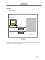
1
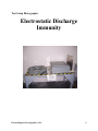
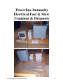
European Union (EU) Council Directive 89/336/EEC
Electromagnetic Compatibility (EMC) Test Report
2620 Modular Measurement
and Control System
Sensoray
March 31, 2006 – April 4, 2006
Tests Conducted by:
ElectroMagnetic Investigations, LLC
20811 NW Cornell Road, Suite 600, Hillsboro, Oregon 97124, USA
Tele (503) 466-1160 Fax (503) 466-1170 [email protected]
Summary Information
Test Item: 2620 Modular Measurement and Control System
Serial Number:
EU EMC Tests in accordance with EU Council Directive 89/336/EEC
Emissions Tests per EN 61326 Test Standard for measurement, control and
laboratory equipment:
Result
Pass
Pass
Pass
Pass
Standard
EN55011 Class A
EN55011 Class A
EN61000-3-2
EN61000-3-3
Description
Radiated Emissions
Conducted Emissions
Powerline Harmonics
Powerline Voltage
Fluctuation & Flicker
Port
Enclosure
AC Mains
AC Mains
AC Mains
Comments
Immunity Tests per EN 61326 (Industrial Levels)
Result
Pass
Standard
EN61000-4-2
Description
Port
Electrostatic
Discharge Enclosure
Immunity
Pass
EN61000-4-3
Pass
EN61000-4-4
Pass
EN61000-4-4
Pass
EN61000-4-5
RF
Electromagnetic
Field
Immunity
Electrical Fast Transient/Burst
(EFT) Immunity
Electrical Fast Transient/Burst
(EFT) Immunity
Electrical
Slow
Transient
(Surge) Immunity
Pass
EN61000-4-6
RF Conducted Immunity
AC Leads
Pass
EN61000-4-6
RF Conducted Immunity
AC Leads
Pass
EN61000-4-11
Voltage Interruption
Immunity
AC Leads
AC Leads
Comments
Tested up to 8 kV air
discharge and 4 kV
contact discharge
10 V/M, 80 to 1000
MHz
2 kV peak
I/O Leads
1000 V peak
AC Leads
1
kV
peak
differential mode
2 kV peak - common
mode
10 V RMS, 150 kHz
to 80 MHz
10 V RMS, 150 kHz
to 80 MHz
0.5
cycle,
100%
dropout
Enclosure
I,
_______ , representative for Sensoray verify that the product
tested is representative of units to be sold.
____________________
(signature)
2
EN 61326 Emissions
3
EN61326 Emissions Test Report
2620 Modular Measurement
and Control System
Sensoray
March 31, 2006
Tests Conducted by:
ElectroMagnetic Investigations, LLC
20811 NW Cornell Road, Suite 600, Hillsboro, Oregon 97124, USA
Tele (503) 466-1160 Fax (503) 466-1170 [email protected]
Table of Contents
EN55011 Class A Test Summary
Page 3
EN55011 Class A test Setup
Page 4
EN55011 Class A Test Results
Page 5
Test Data
Page 5
Test Photographs
Page 6
2
Summary Information
Test Items:
2620 Modular Measurement and Control System
Serial Number:
Requested By:
Caleb Streur
Sensoray
7313 SW Tech Center Dr.
Tigard, OR 97223
503.684.8005 Telephone
Tested By:
Derick Skouby
_____________
Ryan Benitez
_____________
Test Date(s):
Tests Performed:
March 31, 2006
Radiated and conducted electromagnetic interference measurements as per EN55011 Class A.
Test Locations:
ElectoMagnetic Investigations, LLC, Hillsboro, Oregon
Purpose:
The purpose of the testing is to determine if the 2620 Modular Measurement and Control System is
compliant to electromagnetic emission limits as specified by EN61326 product family standard for
measurement, control and laboratory equipment to support compliance to the European Union EMC
Directive 89/336/EEC.
Summary of Results:
EN55011 Class A:
Radiated Emissions: ……………………………. Emissions are within specification limits.
Least Margin: ……………………………………………..……...10.4 dB at 170.2 MHz.
Conducted Emissions: : ………………………. Emissions are within specification limits.
Least Margin: ……………………………………………..……...6.9 dB at 27.9 MHz.
EN61000-3-2/3:
Powerline Harmonic Emissions: ………………. Emissions are within specification limits.
3
Test Method
The 2620 Modular Measurement and Control System was tested in accordance with EN61326
standard. Radiated levels were measured at three meters distance in both horizontal and
vertical antenna polarizations. The radiated emission measurements were maximized by
rotating the device under test 360 degrees and varying the height of the receiving antenna
from 1 to 4 meters.
Test Set-Up
Control PC
Ethernet Cable
Power Cable
2600 EUT
Figure 1
The 2620 (EUT) is connected to the Control PC which is set up outside of the test chamber.
Detector Function:
Peak/Quasi-peak.
Measurement Bandwidths:
150 kHz to 30 MHZ: 9 kHz Peak/ 9 kHz Quasi-Peak
30 MHz to 1000 MHZ: 120 kHz Peak/120 kHz Quasi-Peak
4
Test Results:
The 2620 Modular Measurement and Control System unit tested was verified to be compliant with
EN55011 class A radiated and conducted emission limits.
The 2620 Modular Measurement and Control System unit tested was verified to be compliant with
EN61000-3-2/3 powerline harmonics and powerline fluctuation/flicker specifications.
Test Data:
I. Radiated Emissions
(3-Meter Specifications)
Frequency
(MHz)
71.7
72.3
76.9
78.8
153.8
170.2
Total Level
(dBuV/m)
36
37.3
34.3
38.8
38.8
40
EN55011 Class A Limit
(dBuV/m)
50.4
50.4
50.4
50.4
50.4
50.4
Margin
(dB)
14.4
13.1
16.1
11.6
11.6
10.4
Total Level
(dBuV/m)
47.6
48
50.3
49
48.1
53.1
EN55011 Class A Limit
(dBuV/m)
60
60
60
60
60
60
Margin
(dB)
12.4
12
9.7
11
11.9
6.9
II. Conducted Emissions
Frequency
(MHz)
1.315
1.316
25.95
26.93
27.42
27.9
5
Test Setup Photographs:
Radiated Emissions
6
Conducted Emissions
7
Powerline Harmonics/Powerline
Fluctuations
8
Additional Test Data
9
EN 61326 Immunity
EN61326 Immunity Test Report
2620 Modular Measurement
and Control System
Sensoray
March 31, 2006 – April 4, 2006
Tests Conducted by:
ElectroMagnetic Investigations, LLC
20811 NW Cornell Road, Suite 600, Hillsboro, Oregon 97124, USA
Tele (503) 466-1160 Fax (503) 466-1170 [email protected]
Table of Contents
Test Performed
Page 3
Summary of Results
Page 4
Performance Criteria
Page 7
Test Setup
Page 6
Test Results
Page 7
Test Photographs
Page 9
ElectroMagnetic Investigations, LLC
2
Summary Information
Test Items:
2620 Modular Measurement and Control System
Serial Number:
Requested By:
Caleb Streur
Sensoray
7313 SW Tech Center Dr.
Tigard, OR 97223
503.684.8005 Telephone
Tested By:
Derick Skouby
_____________
Ryan Benitez
_____________
Test Date(s):
March 31, 2006 – April 4, 2006
Tests Performed:
Air, Contact and Indirect Electrostatic Discharge Immunity per basic standard EN61000-4-2 in
accordance with EN61326 product family standard requirements.
RF Electromagnetic Field Immunity per basic standard EN61000-4-3 in accordance with
EN61326 product family standard requirements.
Electrical Fast Transient Immunity per basic standard EN61000-4-4 in accordance with EN61326
product family standard requirements.
Electrical Slow Transient Immunity per basic standard EN61000-4-5 in accordance with
EN61326 product family standard requirements.
RF Conducted Immunity per basic standard EN61000-4-6 in accordance with EN61326 product
family standard requirements.
RF Powerline Interruption Immunity per basic standard EN61000-4-11 in accordance with
EN61326 product family standard requirements.
ElectroMagnetic Investigations, LLC
3
Test Location:
ElectroMagnetic Investigations, LLC, Hillsboro, Oregon
Purpose
The purpose of the testing is to determine if the 2620 Modular Measurement and Control System
is compliant to immunity specifications as per EN61326 product family standard for
measurement, control and laboratory equipment to support compliance to the European Union
EMC Directive 89/336/EEC. Heavy industrial environmental levels were tested.
Summary of Results
EN61000-4-2 RF Electrostatic Discharge Immunity – Pass (performance criteria B)
The 2620 Modular Measurement and Control System complies with performance criteria B as
specified by the manufacturer after subjected to electrostatic discharge. No degradation of
performance was observed after application of electrostatic discharge.
EN61000-4-3 RF Fields Immunity – Pass (performance criteria A)
The 2620 Modular Measurement and Control System operated within the performance criteria
while subjected to an electromagnetic field of 10 V/m with 80% 1 kHz amplitude modulation in
the frequency range from 80 MHz to 1000 MHz. No degradation of performance was observed
beyond performance criteria.
EN61000-4-5 Electrical Fast Transient Immunity – Pass (performance criteria B)
The 2620 Modular Measurement and Control System operated within the performance criteria
after subjected to electrical slow transient to the AC mains. No degradation of performance was
observed.
EN61000-4-5 Electrical Slow Transient Immunity – Pass (performance criteria B)
The 2620 Modular Measurement and Control System operated within the performance criteria
after subjected to electrical slow transient to the AC mains. No degradation of performance was
observed.
EN61000-4-6 RF Conducted Immunity – Pass (performance criteria A)
The 2620 Modular Measurement and Control System operated within the performance criteria
when subjected to an RF conducted signals injected onto the AC mains. No degradation of
performance was observed.
EN61000-4-11 Powerline Voltage Interruption – Pass (performance criteria B)
ElectroMagnetic Investigations, LLC
4
The 2620 Modular Measurement and Control System operated within the performance criteria
after subjected to powerline interruptions to the AC mains. No degradation of performance was
observed.
Description of product:
The 2620 is a modular measurement and control system designed for applications such as
machine control, industrial process control, building automation and remote data acquisition. It
uses Ethernet to connect a LAN to I/O measurement and control points.
Test Methods
EN61000-4-2 Electrostatic Discharge Immunity
The 2620 Modular Measurement and Control System was tested in accordance with EN61000-42 per the methods and limits specified in EN61326.
The 2620 Modular Measurement and Control System, configured as described in Test Setup, was
placed on an insulating support resting on a conductive table 0.8 meters in height. The 2620
Modular Measurement and Control System was subjected to electrostatic discharges from an
Electrostatic Discharge Simulator.
Contact discharges were applied to accessible metal areas of the 2620 Modular Measurement and
Control System, to horizontal coupling plan and to vertical coupling plane placed 10 cm away
from each side of the 2620 Modular Measurement and Control System. Air discharges were
applied to non-metallic areas.
EN61000-4-3 RF Fields Immunity
The 2620 Modular Measurement and Control System was tested in accordance with EN61000-43 per the methods and limits specified in EN61326.
The 2620 Modular Measurement and Control System, configured as described in Test Setup, was
placed on a non-conductive table 1.0 meter in height inside a shielded enclosure.
Electromagnetic fields were generated by antennas placed 3.0 meters in front of the 2620
Modular Measurement and Control System.
While the 2620 Modular Measurement and Control System was monitored for degradation of
performance, the electromagnetic field was maintained at 10 V/m with 80% 1 kHz amplitude
modulation while scanning the frequency range from 80 MHz to 1000 MHz.
EN61000-4-4 Electrical Fast Transient Immunity
ElectroMagnetic Investigations, LLC
5
The 2620 Modular Measurement and Control System was tested in accordance with EN61000-44 per the methods and limits specified in EN61326.
The 2620 Modular Measurement and Control System configured as described in Test Setup, was
placed 10 cm above a conductive surface. The 2620 Modular Measurement and Control System
was subjected to electrical transients/bursts (EFT/B) injected capacitively through a Mains
Coupler/Decoupler onto each of the line, neutral and earth conductors of the EUT power input.
The EFT/B consists of 5 nS rise time, 50 nS duration pulses with a repetition frequency of 5 kHz.
The pulses are delivered in 15 mS bursts with a burst repetition period of 300mS. Both positive
and negative pulses are applied at 1 kV and 2.0 kV peak to each of the conductors described
above for a period of at least 1 minute. The burst transient was injected onto the I/O line at a
level of ±500 V and ±1000 V by a capacitive clamp.
EN61000-4-5 Electrical Slow Transient Immunity
The 2620 Modular Measurement and Control System configured as described in Test Setup, was
placed on a non-conductive table 0.8 meter in height. The 2620 Modular Measurement and
Control System was subjected to electrical power line surge transients injected capacitively
through a Mains Coupler/Decoupler onto the conductors of the EUT power input. The surges
have an open circuit voltage waveform with a rise time of 1.2 µS and duration of 50 µS, and a
short circuit waveform with a rise time of 8 µS and duration of 20 µS.. Surges are applied to
each of the line and neutral conductors with respect to earth ground (common mode) at 0.5 kV, 1
kV and 2 kV. Surges are also applied differentially across the line and neutral conductors at 0.5
kV and 1 kV. Both 5 positive and 5 negative surges are applied at 0°, 90°, 180°, and 270° phase
angles for each voltage and configuration.
EN61000-4-6 RF Conducted Immunity
The 2620 Modular Measurement and Control System configured as described in Test Setup, was
placed .1 meters above a conductive table. The 2620 Modular Measurement and Control System
AC mains lines and I/O were subjected to 10 Vrms RF signals swept from 150 kHz to 80 MHz
with 80% amplitude modulation with a 1 kHz sine wave.
EN61000-4-11 RF Voltage Interruption
The 2620 Modular Measurement and Control System configured as described in Test Setup, was
placed on a non-conductive table 0.80 meter in height. The 2620 Modular Measurement and
Control System AC mains lines were subjected to 100% interruption of the powerline voltage for
a period of 0.5 cycles.
ElectroMagnetic Investigations, LLC
6
Performance Criteria
A – No degradation of performance during application of EMC phenomena. (EN61000-4-3,
EN61000-4-6).
B - No degradation of performance after application of EMC phenomena. (EN61000-4-2,
EN61000-4-4, EN61000-4-5, EN61000-4-11).
Test Set-Up
Control PC
Ethernet Cable
Power Cable
2600 EUT
Figure 1
The 2620 (EUT) is connected to the Control PC which is set up outside of the test chamber.
Test Results
EN61000-4-2 per EN61326 product family requirements (Electrostatic Discharge)
No degradation of operation was observed after the test.
ElectroMagnetic Investigations, LLC
7
EN61000-4-3 per EN61326 product family requirements (RF Fields)
No degradation of operation was observed during or after the test.
EN61000-4-4 per EN61326 product family requirements (EFT/B)
No degradation of operation was observed during or after the test.
EN61000-4-5 per EN61326 product family requirements (Surge)
No degradation of operation was observed during or after the test.
EN61000-4-6 per EN61326 product family requirements (RF Conducted)
No degradation of operation was observed during or after the test.
EN61000-4-11 per EN61326 product family requirements (Voltage Interruption)
No degradation of operation was observed during or after the test.
ElectroMagnetic Investigations, LLC
8
Test Setup Photographs:
Electrostatic Discharge
Immunity
ElectroMagnetic Investigations, LLC
9
RF Radiated Immunity
ElectroMagnetic Investigations, LLC
10
Powerline Immunity
Electrical Fast & Slow
Transient & Dropouts
ElectroMagnetic Investigations, LLC
11
RF Conducted Immunity
ElectroMagnetic Investigations, LLC
12
EN61326 EMC Test Plan
ElectroMagnetic Investigations, LLC
13
Sensoray
EMC Test Plan
Product Model Number:
2600 Series
Products included in this product group: 2601, 2608, 2610, 2620, 2650, 2652
Description of product:
The 2600 is a modular measurement and control system designed for applications such as machine
control, industrial process control, building automation and remote data acquisition. It uses Ethernet to
connect a LAN to I/O measurement and control points.
Revision History
Rev
1.0
Date
3/22/2006
Author:
Reason for Amendment – description of change
First Issue
Caleb Streur, Applications Engineer
Introduction
This document contains the proposed EMC test procedure and method of evaluation for the product
described above. Testing will be per EN61326 electromagnetic compatibility product family test standard
for measurement, control and laboratory equipment.
Test
Configurations,
Criteria
Procedures
and
Performance
Non-Industrial Class
In the following tests, we are using the non-industrial class
specifications.
Test & Measurement Type
This EUT is considered to be a Test & Measurement type of equipment, and follows the specifications
for this type of device.
1) Electrostatic Discharge (ESD) Immunity
The Test Setup is described in the Appendix in Figure 1, and is further described as follows: The
2600 (EUT) is connected to a PC via an Ethernet cable. All three devices are on the ESD Test Table
and insulated from the surface. The ESD Test Table has a conductive table top and is connected to
Page 1
Sensoray
EMC Test Plan
Earth ground via a test standard specified resistor. The ESD Simulator is connected to the surface of
the ESD table.
We will note any reaction by the unit to the conducted & radiated energy by observing the display
of the control PC.
Page 2
Sensoray
EMC Test Plan
Performance Criteria - ESD
Performance Criteria B, as described in the Appendix of this Test
Plan, will be used for this test.
The ESD Immunity test requirements are described by the EN610004-2 specification. The test consists of simulated ESD events by
contact & air discharge to the EUT case. Discharges within 10cm of
the EUT will also be performed on the horizontal & vertical planes of
the ESD Test Table. Discharges of positive & negative voltages of
2kV and 4kV are required by the standard (non-industrial class).
To provide a level of margin, we will also test the EUT at positive and
negative 6kV and 8kV levels. Any degradation of performance at
these elevated levels will not be considered a failure, but will be noted
in the Test Results.
We do not expect any significant change in performance. Acceptable
performance will be that the measured energy may only change
during the ESD event. For this test the measured energy may exceed
the probe specifications during the ESD event. The EUT will not
change states and will not require user intervention to resume making
accurate measurements after the ESD event.
2) Radiated Immunity
We will use the Test Setup as described in the Appendix of this Test Plan as in Figure 1. This
setup is considered worst case for this test.
We will note any reaction by the EUT to the RF field by observing the display of the control PC.
Performance Criteria – Radiated Immunity
Page 3
Sensoray
EMC Test Plan
Performance Criteria A, as described in the Appendix of this Test
Plan, will be used for this test.
The Radiated Immunity test requirements are defined by the
EN61000-4-3 specification. The test consists of an RF signal from 80
to 1,000MHz modulated 80% AM @ 1 kHz sine wave. The signal
strength at the EUT shall 3V/m at horizontal and vertical polarizations.
We do not expect any significant change in performance. Acceptable
performance will be a reading on the EUT that is within 5% of the
expected result while the system is exposed to the RF field.
3) Conducted Immunity
We will use the Test Setup as described in the Appendix of this Test plan as in Figure 1. This
setup is considered to represent a typical user setup.
Performance Criteria – Conducted Immunity
Performance Criteria B, as described in the Appendix of this Test Plan, will be used for this test.
The Conducted Immunity test requirements are defined by the EN61000-4-6 specification. The
test consists of the injection of a 10 Vrms 80% AM sine from 150 kHz to 80MHz signal.
We do not expect any significant change in performance. Acceptable performance will be a
reading on the EUT that is within 5% of the expected result while the system is exposed to the RF
field.
4) Electrical Fast Transient Immunity (Burst)
We will use the Test Setup as described in the Appendix of this Test plan as in Figure 1. This setup
is considered to represent a typical user setup.
Performance Criteria – EFT Immunity (Burst)
Performance Criteria B, as described in the Appendix of this Test Plan, will be used for this test.
The EFT Immunity test requirements are defined by the EN61000-4-4 specification. The test
consists of the injection of 1.0kV onto the AC line.
Page 4
Sensoray
EMC Test Plan
We do not expect any significant change in performance. Acceptable performance will be a
reading on the EUT that is within 5% of the expected result after the system is exposed to the RF
energy.
5) Electrical Slow Transient Immunity (Surge)
We will use the Test Setup as described in the Appendix of this Test plan as in Figure 1. This setup
is considered to represent a typical user setup.
Performance Criteria – Electrical Slow Transient Immunity (Surge)
Performance Criteria B, as described in the Appendix of this Test Plan, will be used for this test.
The Electrical Slow Transient Immunity test requirements are defined by the EN61000-4-5
specification. The test consists of the injection of 500V Line to Line & 1kV Line to Earth onto the
AC line.
We do not expect any significant change in performance. Acceptable performance will be a
reading on the EUT that is within 5% of the expected result after the system is exposed to the RF
energy.
6) Voltage Interrupt Immunity
We will use the Test Setup as described in the Appendix of this Test plan as in Figure 1. This setup
is considered to represent a typical user setup.
Performance Criteria – Voltage Interrupt Immunity
Performance Criteria B, as described in the Appendix of this Test Plan, will be used for this test.
The Voltage Interrupt Immunity test requirements are defined by the EN61000-4-11 specification.
The test consists of removing power for one complete cycle (50Hz).
We do not expect any significant change in performance. Acceptable performance will be a
reading on the EUT that is within 5% of the expected result after the system is exposed to the
Voltage Interrupt.
7) Radiated Emissions
We will use the Test Setup as described in the Appendix of this Test plan as in Figure 1. This setup
is considered to represent a typical user setup.
We will observe the emissions radiated from this EUT with a recording spectrum analyzer and note
in the Test Results, the levels of emissions and their frequency.
Performance Criteria – Radiated Emissions
Page 5
Sensoray
EMC Test Plan
The Radiated Emissions test limits are defined by the EN61326 Class
A specification. We will be measuring RF Emissions from the EUT at
3 meters.
8) Conducted Emissions
We will use the Test Setup as described in the Appendix of this Test plan as in Figure 1. This setup
is considered to represent a typical user setup.
We will observe the emissions radiated from this EUT with a recording spectrum analyzer and note in
the Test Results, the levels of emissions and their frequencies.
Performance Criteria – Conducted Emissions
The Conducted Emissions test limits are defined by the EN61326 Class A specification.
End of
Test Configurations, Procedures and Performance Criteria
Page 6
Sensoray
EMC Test Plan
Appendix
Test Setups
Control PC
Ethernet Cable
Power Cable
2600 EUT
Figure 1
The 2600 (EUT) is connected to the Control PC which is set up outside of the test chamber. The EUT is
monitored for any changes during the EMI events.
Page 7
Sensoray
EMC Test Plan
Performance Criteria A Definition
The EUT (Equipment Under Test) may react to the EMI energy but may not change states or
require user intervention to continue making accurate measurements after the EMI event. No
degradation of the product tolerances or specifications is allowed. The output measurement of
the EUT shall be within 5% of the expected result, while being exposed to the EMI energy,
and return to normal upon removal of the EMI energy.
Performance Criteria B Definition
The EUT may react to the EMI energy during the event (ESD), but may not change states or
require user intervention to continue making accurate measurements after the EMI event. If
the output measurement of the EUT is beyond 5% of the expected results during a continuous
EMI test (i.e. Radiated or Conducted RF Immunity), this information is to be declared on the
product or in the User Manual for the product.
Performance Criteria C Definition
The EUT temporarily stops functioning and requires user intervention to bring it back to a
normal operating condition (during or after the EMI energy exposure).
Performance Criteria D Definition
The EUT permanently stops functioning, or is permanently damaged by the EMI energy.
Degradation or loss of function which is not recoverable due to damage to equipment,
components, or the software. Any EUT that falls into this category is not CE compliant.
Page 8