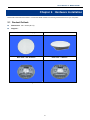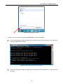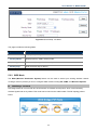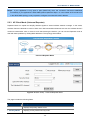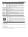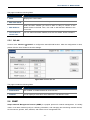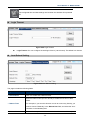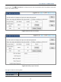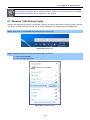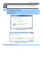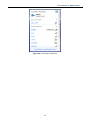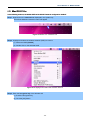
1
Copyright Copyright 2014 by PLANET Technology Corp. All rights reserved. No part of this publication may be reproduced, transmitted, transcribed, stored in a retrieval system, or translated into any language or computer language, in any form or by any means, electronic, mechanical, magnetic, optical, chemical, manual or otherwise, without the prior written permission of PLANET. PLANET makes no representations or warranties, either expressed or implied, with respect to the contents hereof and specifically disclaims any warranties, merchantability or fitness for any particular purpose. Any software described in this manual is sold or licensed "as is". Should the programs prove defective following their purchase, the buyer (and not PLANET, its distributor, or its dealer) assumes the entire cost of all necessary servicing, repair, and any incidental or consequential damages resulting from any defect in the software. Further, PLANET reserves the right to revise this publication and to make changes from time to time in the contents hereof without obligation to notify any person of such revision or changes. All brand and product names mentioned in this manual are trademarks and/or registered trademarks of their respective holders. Federal Communication Commission Interference Statement This equipment has been tested and found to comply with the limits for a Class B digital device, pursuant to Part 15 of FCC Rules. These limits are designed to provide reasonable protection against harmful interference in a residential installation. This equipment generates, uses, and can radiate radio frequency energy and, if not installed and used in accordance with the instructions, may cause harmful interference to radio communications. However, there is no guarantee that interference will not occur in a particular installation. If this equipment does cause harmful interference to radio or television reception, which can be determined by turning the equipment off and on, the user is encouraged to try to correct the interference by one or more of the following measures: 1. Reorient or relocate the receiving antenna. 2. 3. 4. Increase the separation between the equipment and receiver. Connect the equipment into an outlet on a circuit different from that to which the receiver is connected. Consult the dealer or an experienced radio technician for help. FCC Caution To assure continued compliance, use only shielded interface cables when connecting to computer or peripheral devices. Any changes or modifications not expressly approved by the party responsible for compliance could void the user’s authority to operate the equipment. This device complies with Part 15 of the FCC Rules. Operation is subject to the following two conditions: (1) This device may not cause harmful interference (2) This Device must accept any interference received, including interference that may cause undesired operation. Any changes or modifications not expressly approved by the party responsible for compliance could void the user’s authority to operate the equipment. I Federal Communication Commission (FCC) Radiation Exposure Statement This equipment complies with FCC radiation exposure set forth for an uncontrolled environment. In order to avoid the possibility of exceeding the FCC radio frequency exposure limits, human proximity to the antenna shall not be less than 20 cm (8 inches) during normal operation. R&TTE Compliance Statement This equipment complies with all the requirements of DIRECTIVE 1999/5/CE OF THE EUROPEAN PARLIAMENT AND THE COUNCIL OF 9 March 1999 on radio equipment and telecommunication terminal Equipment and the mutual recognition of their conformity (R&TTE). The R&TTE Directive repeals and replaces in the directive 98/13/EEC (Telecommunications Terminal Equipment and Satellite Earth Station Equipment) as of April 8, 2000. Safety This equipment is designed with the utmost care for the safety of those who install and use it. However, special attention must be paid to the dangers of electric shock and static electricity when working with electrical equipment. All guidelines of this and of the computer manufacture must therefore be allowed at all times to ensure the safe use of the equipment. National Restrictions This device is intended for home and office use in all EU countries (and other countries following the EU directive 1999/5/EC) without any limitation except for the countries mentioned below: Country Restriction Bulgaria None France Reasons/remarks General authorization required for outdoor use and public service Outdoor use; limited to 10 Military Radiolocation use. Refarming of the 2.4 GHz mW e.i.r.p. within the band band has been ongoing in recent years to allow current 2454-2483.5 MHz relaxed regulation. Full implementation planned 2012 Italy None Luxembourg None Norway Implemented Russian None If used outside of own premises, general authorization is required General authorization required for network and service supply(not for spectrum) This subsection does not apply for the geographical area within a radius of 20 km from the centre of Ny-Ålesund Only for indoor applications Federation Note: Please don’t use the product outdoors in France. WEEE regulation To avoid the potential effects on the environment and human health as a result of the presence of hazardous substances in electrical and electronic equipment, end users of electrical and electronic equipment should understand the meaning of the crossed-out wheeled bin symbol. Do not dispose of WEEE as unsorted municipal waste and have to collect such WEEE separately. II Revision User Manual for PLANET 300Mbps 802.11n Wireless Ceiling Mount AP/ Range Extender Model: WNAP-C3220 Rev: 2.0 (July, 2014) Part No. EM-WNAP-C3220v2_v2.0 (2081-E10400-003) III CONTENTS Chapter 1.Product Introduction...........................................................................................................1 1.1 Package Contents ...............................................................................................................1 1.2 Product Description............................................................................................................2 1.3 Product Features................................................................................................................. 5 1.4 Product Specifications ....................................................................................................... 6 Chapter 2.Hardware Installation ..........................................................................................................8 2.1 Product Outlook .................................................................................................................. 8 2.1.1 Panel Layout............................................................................................................. 9 2.1.2 Hardware Description .............................................................................................10 Chapter 3.Connecting to the AP ........................................................................................................ 11 3.1 System Requirements ...................................................................................................... 11 3.2 Installing the AP ................................................................................................................ 11 Chapter 4.Quick Installation Guide ...................................................................................................14 4.1 Manual Network Setup - TCP/IP Configuration ..............................................................14 4.1.1 4.2 Configuring the IP Address Manually .....................................................................14 Starting Setup in the Web UI ............................................................................................18 Chapter 5.Configuring the AP............................................................................................................19 5.1 Status..................................................................................................................................19 5.2 Quick Setup .......................................................................................................................23 5.2.1 AP Mode .................................................................................................................23 5.2.2 WDS Mode .............................................................................................................24 5.2.3 AP Client Mode (Universal Repeater) ....................................................................29 5.3 LAN Setup ..........................................................................................................................32 5.4 DHCP Server ......................................................................................................................33 5.5 5.4.1 DHCP Server ..........................................................................................................33 5.4.2 DHCP Client List.....................................................................................................34 Wireless..............................................................................................................................36 5.5.1 Basic .......................................................................................................................36 5.5.2 Radio.......................................................................................................................38 5.5.3 Advanced................................................................................................................39 5.5.4 Wireless Access Control .........................................................................................40 5.5.5 QVLAN....................................................................................................................41 5.6 SNMP ..................................................................................................................................41 5.7 Tools ...................................................................................................................................43 5.7.1 Maintenance ...........................................................................................................43 5.7.2 Time ........................................................................................................................44 5.7.3 Logs ........................................................................................................................46 IV 5.7.4 Backup Settings......................................................................................................47 5.7.5 Set Password..........................................................................................................48 5.7.6 Diagnostics .............................................................................................................50 Chapter 6.Quick Connection to a Wireless Network .......................................................................51 6.1 Windows XP (Wireless Zero Configuration)...................................................................51 6.2 Windows 7 (WLAN AutoConfig).......................................................................................53 6.3 Mac OS X 10.x....................................................................................................................56 6.4 iPhone / iPod Touch / iPad ...............................................................................................60 Appendix A: Planet Smart Discovery Utility.....................................................................................63 Appendix B: Troubleshooting............................................................................................................64 Appendix C: Specifications................................................................................................................66 Appendix D: Glossary.........................................................................................................................68 V FIGURE FIGURE 2-1 WNAP-C3220 PRODUCT OUTLOOK .................................................................................................... 8 FIGURE 2-2 WNAP-C3220 FRONT PANEL LAYOUT ................................................................................................ 9 FIGURE 2-3 WNAP-C3220 REAR PANEL LAYOUT .................................................................................................. 9 FIGURE 3-1 WNAP-C3220 INSTALLATION DIAGRAM 1........................................................................................ 11 FIGURE 3-2 WNAP-C3220 INSTALLATION DIAGRAM 2........................................................................................ 12 FIGURE 3-3 WNAP-C3220 INSTALLATION DIAGRAM 3........................................................................................ 12 FIGURE 3-4 WNAP-C3220 INSTALLATION DIAGRAM 4........................................................................................ 12 FIGURE 3-5 WNAP-C3220 INSTALLATION DIAGRAM 5........................................................................................ 13 FIGURE 4-1 TCP/IP SETTING ................................................................................................................................ 15 FIGURE 4-2 WINDOWS START MENU .................................................................................................................... 16 FIGURE 4-3 SUCCESSFUL RESULT OF PING COMMAND .......................................................................................... 16 FIGURE 4-4 FAILED RESULT OF PING COMMAND ................................................................................................... 17 FIGURE 4-5 LOGIN BY DEFAULT IP ADDRESS ......................................................................................................... 18 FIGURE 4-6 LOGIN WINDOW ................................................................................................................................ 18 FIGURE 5-1 MAIN MENU ...................................................................................................................................... 19 FIGURE 5-2 SYSTEM STATUS ................................................................................................................................. 20 FIGURE 5-3 WIRELESS STATUS ............................................................................................................................. 21 FIGURE 5-4 TRAFFIC STATISTICS .......................................................................................................................... 22 FIGURE 5-5 WIRELESS CLIENTS............................................................................................................................ 22 FIGURE 5-6 QUICK SETUP - AP MODE .................................................................................................................. 24 FIGURE 5-7 QUICK SETUP - WDS MODE .............................................................................................................. 25 FIGURE 5-8 WDS -1 ............................................................................................................................................. 26 FIGURE 5-9 WDS -2 ............................................................................................................................................. 27 FIGURE 5-10 WDS -3 ........................................................................................................................................... 28 FIGURE 5-11 WDS -4............................................................................................................................................ 28 FIGURE 5-12 QUICK SETUP - UNIVERSAL REPEATER MODE.................................................................................. 29 FIGURE 5-13 AP CLIENT -1................................................................................................................................... 30 FIGURE 5-14 AP CLIENT -2................................................................................................................................... 31 FIGURE 5-15 AP CLIENT -3................................................................................................................................... 31 FIGURE 5-16 AP CLIENT -4................................................................................................................................... 32 FIGURE 5-17 LAN SETUP ..................................................................................................................................... 32 FIGURE 5-18 DHCP SERVER ................................................................................................................................. 34 FIGURE 5-19 DHCP CLIENT LIST ......................................................................................................................... 35 FIGURE 5-20 WIRELESS BASIC ............................................................................................................................. 36 FIGURE 5-21 WIRELESS RADIO ............................................................................................................................. 38 FIGURE 5-22 WIRELESS ADVANCED ..................................................................................................................... 39 FIGURE 5-23 WIRELESS ACCESS CONTROL........................................................................................................... 40 FIGURE 5-24 WIRELESS QVLAN ......................................................................................................................... 41 FIGURE 5-25 SNMP ............................................................................................................................................. 42 FIGURE 5-26 FIRMWARE UPGRADE ....................................................................................................................... 43 FIGURE 5-27 REBOOT ........................................................................................................................................... 43 FIGURE 5-28 SYSTEM TIME .................................................................................................................................. 44 VI FIGURE 5-29 LOGIN TIMEOUT .............................................................................................................................. 45 FIGURE 5-30 AUTO REBOOT SETTING .................................................................................................................. 45 FIGURE 5-31 VIEW LOGS ...................................................................................................................................... 46 FIGURE 5-32 LOG SETUP ...................................................................................................................................... 46 FIGURE 5-33 ADD LOG SERVER ............................................................................................................................ 47 FIGURE 5-34 BACKUP & RESTORE ........................................................................................................................ 48 FIGURE 5-35 RESTORE TO FACTORY DEFAULT ...................................................................................................... 48 FIGURE 5-36 USER NAME & PASSWORD ............................................................................................................... 49 FIGURE 5-37 SETTING LOGIN PASSWORD ............................................................................................................. 49 FIGURE 5-38 DIAGNOSTICS................................................................................................................................... 50 FIGURE 6-1 SYSTEM TRAY – WIRELESS NETWORK ICON ...................................................................................... 51 FIGURE 6-2 CHOOSE A WIRELESS NETWORK ......................................................................................................... 51 FIGURE 6-3 ENTER THE NETWORK KEY................................................................................................................. 52 FIGURE 6-4 CHOOSE A WIRELESS NETWORK -- CONNECTED ................................................................................. 52 FIGURE 6-5 NETWORK ICON ................................................................................................................................. 53 FIGURE 6-6 WLAN AUTOCONFIG ........................................................................................................................ 53 FIGURE 6-7 TYPE THE NETWORK KEY ................................................................................................................... 54 FIGURE 6-8 CONNECTING TO A NETWORK ............................................................................................................ 54 FIGURE 6-9 CONNECTED TO A NETWORK.............................................................................................................. 55 FIGURE 6-10 MAC OS – NETWORK ICON .............................................................................................................. 56 FIGURE 6-11 HIGHLIGHT AND SELECT THE WIRELESS NETWORK ........................................................................... 56 FIGURE 6-12 ENTER THE PASSWORD .................................................................................................................... 57 FIGURE 6-13 CONNECTED TO THE NETWORK ....................................................................................................... 57 FIGURE 6-14 SYSTEM PREFERENCES .................................................................................................................... 58 FIGURE 6-15 SYSTEM PREFERENCES -- NETWORK ................................................................................................ 58 FIGURE 6-16 SELECT THE WIRELESS NETWORK ................................................................................................... 59 FIGURE 6-17 IPHONE – SETTINGS ICON ................................................................................................................. 60 FIGURE 6-18 WI-FI SETTING ................................................................................................................................. 60 FIGURE 6-19 WI-FI SETTING – NOT CONNECTED .................................................................................................. 61 FIGURE 6-20 TURN ON WI-FI ................................................................................................................................ 61 FIGURE 6-21 IPHONE -- ENTER THE PASSWORD .................................................................................................... 62 FIGURE 6-22 IPHONE -- CONNECTED TO THE NETWORK ....................................................................................... 62 VII User Manual of WNAP-C3220 Chapter 1. Product Introduction 1.1 Package Contents Thank you for choosing PLANET WNAP-C3220. Before installing the AP, please verify the contents inside the package box. WNAP-C3220 Quick Installation Guide CD-ROM (User Manual included) Ethernet Cable Power Adapter Mounting Kit If there is any item missing or damaged, please contact the seller immediately. -1- User Manual of WNAP-C3220 1.2 Product Description PLANET WNAP-C3220 is a stylish PoE Wireless Access Point featuring the latest wireless technology and unique ceiling-mount artistic design. It offers 300Mbps 802.11n wireless speed, multiple operation modes and 802.3af Power over Ethernet features to increase client mobility and speed within a network. Sleek styling housing and ceiling mountable design make the WNAP-C3220 blend unobtrusively into any ceiling or wall for various environments. This perfect product also creates a secure, cost-effective and highly-scalable wireless LAN infrastructure. It is ideal for enterprises, hotels, hospitals and home users to extend wireless network coverage. Ultra High-speed 802.11n Wireless Type The WNAP-C3220 features the latest IEEE 802.11n radio with 2T2R MIMO antenna technology to provide improved wireless speed and coverage with up to 300Mbps upload and download data rate. The incredibly wireless speed makes it ideal for handling multiple HD movie streams, high-resolution on-line game, stereo music, and VoIP and data streams at the same time stably and smoothly. It is also backward compliant with 802.11g and 802.11b standards and thus it is no need to change the existing network for convenient maintenance. Just connect to the WNAP-C3220 and you can immediately enjoy the high-speed wireless sharing. Multiple Operating Modes The WNAP-C3220 supports multiple devices in a wireless communication connectivity: wireless AP, wireless Repeater, and WDS Point-to-Point (PtP) and Point-to-Multipoint (PtMP), allowing users to comprehensively experience various applications. It also helps users to easily build wireless network and extend the wireless range of the existing wireless network. -2- User Manual of WNAP-C3220 Advanced Wireless Security In aspect of security, besides 64/128-bit WEP encryption, the WNAP-C3220 integrates WPA/WPA2, WPA-PSK/WPA2-PSK and 802.1x authority to secure and protect your wireless LAN. It provides the wireless MAC filtering and SSID broadcast control to consolidate the wireless network security and prevent unauthorized wireless connection. Unique Ceiling-mountable Design Featuring attractive flying saucer appearance and ceiling-mountable design, the WNAP-C3220 can be firmly adsorbed on the ceiling or the wall, which is easy and convenient for client-side installation. Its streamlined body without protruding antennas also gives effects of embellishment on the surroundings. Wireless Range Extender for Home The WNAP-C3220 is the characterization of ceiling mounting design and advanced MIMO technology which reduces the effect of dead spot, so that it can get a better coverage of the existing wireless network. The WDS and repeater modes by the WNAP-C3220 minimize installation and cabling costs. Easy Installation and Management With user-friendly Web UI and step by step wizard of the WNAP-C3220, it is easy for users to install the device, even for a user who never experiences in setting up a wireless network. Its SNMP feature allows the system administrator to remotely monitor and control the network devices more efficiently. Flexible Deployment with PoE Feature Compliant with IEEE 802.3af Power over Ethernet standard, the WNAP-C3220 can be powered and networked by a single UTP cable. It thus reduces the needs of extra cables and dedicated electrical outlets on the wall, ceiling or any other place which is difficult to reach. The wireless AP deployment becomes more flexible and frees you from worry about the power outlet locations. -3- User Manual of WNAP-C3220 -4- User Manual of WNAP-C3220 1.3 Product Features Standard Compliant Hardware Interface Complies with IEEE 802.11b/g/n Wireless LAN speed up to 300Mbps 1 x 10/100BASE-TX Port with 1-port PoE (PD, Powered Device) Supports 802.3af standard-based PoE or local AC power Secure Network Connection Advanced security: 64/128-bit WEP, WPA/WPA2, WPA-PSK/WPA2-PSK (TKIP/AES encryption) and Radius Authentication Supports MAC address Filtering to limit the connected wireless clients Supports Multiple SSIDs to allow users to access different networks through a single AP Multiple Operating Modes, Multiple Mounting Options Multiple operating modes including AP, Repeater, WDS Point to Point and WDS Point to Multiple Point Stylish and ceiling mountable design Easy Installation & Management Step by Step configuration with Intelligent Setup Wizard User-friendly Web and SNMP-based management interface System status monitoring includes Associated Client List, System Log Centralized Management Utility allows administrator to monitor and configure -5- User Manual of WNAP-C3220 1.4 Product Specifications Product WNAP-C3220 300Mbps 802.11n Wireless Ceiling Mount Range Extender Hardware Specifications Interface LAN: 1x 10/100BASE-TX, Auto-MDI/MDIX, 802.3af PoE compliant Wireless: IEEE 802.11b/g/n PoE IEEE 802.3af PoE Antenna Built-in 3dBi antenna x2 Reset Button Reset button on rear panel Press over 7 seconds to reset the device to factory default LED Indicators PWR/SYS LED x1 Material Plastic Dimensions (Φ x H) 144 x 33mm Weight 165g Power Requirements Power Consumption Power Supply: DC 12V, 1A Power over Ethernet: IEEE 802.3af PoE, DC 48V, 0.35A 11.26W (max.) Wireless Interface Specifications Transmission / Emission Type: DSSS / OFDM Modulation Type Data modulation type: OFDM: BPSK, QPSK, 16-QAM, 64-QAM, DBPSK, DQPSK, CCK Frequency Band Operating Channel Channel Width 2.412~2.484GHz America/ FCC: 2.412~2.462GHz (11 Channels) Europe/ ETSI: 2.412~2.472GHz (13 Channels) 20 or 20/40MHz IEEE 802.11b: 1/ 2/ 5.5/ 11Mbps Data Rate IEEE 802.11g: 6/ 9/ 12/ 18/ 24/ 36/ 48/ 54Mbps IEEE 802.11n: 300 Mbps in 40MHz mode / 150Mbps in 20MHz mode IEEE 802.11b: -92dBm @ 1Mbps; -85dBm @ 11Mbps, PER < 8% Receiver Sensitivity IEEE 802.11g: -88dBm @ 6Mbps; -73dBm @ 54Mbps, PER <10% IEEE 802.11n: -90dBm @ MCS8; -70dBm @ MCS15, PER <10% RF Power (Intentional Radiator) Transmission Distance 20dBm (max.) Indoor up to 100m Outdoor up to 300m (it is limited to the environment) Wireless Management Features Wireless Modes Access Point, WDS PtP, WDS PtMP, Universal Repeater Multiple-SSIDs Up to 4 WDS Remote Peers Up to 4 -6- User Manual of WNAP-C3220 WEP (64/128-bit) Encryption Security WPA-PSK (TKIP) / WPA2-PSK (AES) WPA (TKIP) / WPA2 (AES) 802.1x Authentication Wireless Security Wireless Advanced Max. Supported Clients Enable/Disable SSID Broadcast Wireless LAN ACL (Access Control List) MAC filtering AP Isolation: Enable it to isolate each connected wireless client Supports 802.11e WMM (Wi-Fi Multimedia) Wired 253 Wireless 40 Web-based (HTTP) management interface System Management Supports SNMP V1 and V2C Supports Planet Smart Discovery & Centralized Management Utility System Log Standards Conformance IEEE Standards Others Protocols and Standards IEEE 802.11n IEEE 802.11g IEEE 802.11b IEEE 802.11i IEEE 802.3 10Base-T IEEE 802.3u 100Base-TX CSMA/CA, CSMA/CD, TCP/IP, DHCP, ICMP, SNTP Environment & Certification Temperature Humidity Regulatory Operating: -10 ~ 45 degrees C Storage: -30 ~ 70 degrees C Operating: 10 ~ 90% (non-condensing) Storage: 10 ~ 90% (non-condensing) CE, RoHS, WEEE -7- User Manual of WNAP-C3220 Chapter 2. Hardware Installation Please follow the instructions below to connect the WNAP-C3220 to the existing network devices and your computers. 2.1 Product Outlook Dimensions: 144 x 33mm (Φ x H) Diagram : Front View – LED Display Side View – Reset Button Rear View – DC Jack Port Rear View – LAN Port Figure 2-1 WNAP-C3220 Product Outlook -8- User Manual of WNAP-C3220 2.1.1 Panel Layout The front and rear panel provide a simple interface monitoring the AP. Figure 2-2 and Figure 2-3 show the hardware interface of the WNAP-C3220. Front Panel - LED Figure 2-2 WNAP-C3220 Front Panel Layout Rear Panel – Port & Button Figure 2-3 WNAP-C3220 Rear Panel Layout -9- User Manual of WNAP-C3220 2.1.2 Hardware Description LED definition Object PWR Color Green State Description On Power on Flashing The system is initializing Off LED enabled: Neither Power nor the device is malfunctioned LED disabled: the device power off or the LED is switched to off Button definition Object Reset Description Press the Reset button over 7 seconds and then release it. The system restores to the factory default settings. H/W Interface definition Object PoE Port (802.3af PoE) Power Connector Description 10/100Mbps RJ45 port , Auto MDI/ MDI-X Connect PoE port to the IEEE 802.3af PoE switch to power on the device. Connect this port to the 12V DC power adapter to power on the device. -10- User Manual of WNAP-C3220 Chapter 3. Connecting to the AP 3.1 System Requirements Broadband Internet Access Service (Cable/xDSL/Ethernet connection) One PoE switch (supply power to the WNAP-C3220) PC with a working Ethernet adapter and an Ethernet cable with RJ45 connectors PC running Windows 98/ME, NT4.0, 2000/XP, Windows Vista / Win 7, MAC OS 9 or later, Linux, UNIX or other platforms compatible with TCP/IP protocols. The above PC is installed with Web browser. 1. The AP in the following instructions means PLANET WNAP-C3220. 2. It is recommended to use Internet Explore 7.0 or above to access the AP. 3.2 Installing the AP Before installing the AP, make sure your PoE switch is connected to the Internet through the broadband service successfully at this moment. If there is any problem, please contact your local ISP. After that, please install the AP according to the following steps. Don't forget to pull out the power plug and keep your hands dry. Step 1. Attach the bracket to the wall or ceiling, and mark each point in the bracket for the screws. Remove the bracket to drill the points and insert the plastic wall-mounts. Use screws to lock the bracket with a screw driver. Figure 3-1 WNAP-C3220 Installation Diagram 1 -11- User Manual of WNAP-C3220 Step 2. Plug the RJ45 Ethernet cable into the WNAP-C3220. Figure 3-2 WNAP-C3220 Installation Diagram 2 Step 3. Plug the power adapter into the WNAP-C3220. If the WNAP-C3220 is connected to an 802.3af PoE switch in Step 2, you don’t have to plug the power adapter. Figure 3-3 WNAP-C3220 Installation Diagram 3 Step 4. Attach the WNAP-C3220 to the mounting bracket. Figure 3-4 WNAP-C3220 Installation Diagram 4 Step 5. Installation is successfully completed. -12- User Manual of WNAP-C3220 Figure 3-5 WNAP-C3220 Installation Diagram 5 1. ONLY use the power adapter supplied with the WNAP-C3220. Otherwise, the product may be damaged. 2. For the power supply of the WNAP-C3220, you could use either IEEE 802.3af PSE device or 12V DC adapter. Please do not use 12V adapter and PSE device at the same time. It may damage the WNAP-C3220 itself. -13- User Manual of WNAP-C3220 Chapter 4. Quick Installation Guide This chapter will show you how to configure the basic functions of your AP within minutes. A computer with wired Ethernet connection to the Wireless AP is required for the first-time configuration. 4.1 Manual Network Setup - TCP/IP Configuration The default IP address of the WNAP-C3220 is 192.168.1.253. And the default Subnet Mask is 255.255.255.0. These values can be changed as you desire. In this guide, we use all the default values for description. Connect the WNAP-C3220 with your PC by an Ethernet cable plugging in LAN port on one side and in LAN port of PC on the other side. Please power on the WNAP-C3220 by PoE from PoE switch. In the following sections, we’ll introduce how to install and configure the TCP/IP correctly on Windows 7. And the procedures in other operating systems are similar. First, make sure your Ethernet Adapter is working, and refer to the Ethernet adapter manual if needed. 4.1.1 Configuring the IP Address Manually Summary: Set up the TCP/IP Protocol for your PC. Configure the network parameters. The IP address is 192.168.1.xxx (if the default IP address of the WNAP-C3220 is 192.168.1.253, and the DSL router is 192.168.1.254, the "xxx" can be configured to any number from 1 to 252), Subnet Mask is 255.255.255.0. 1 Select Use the following IP address radio button to configure the IP address of the PC. 2 For example, as the default IP address of the WNAP-C3220 is 192.168.1.253 and the DSL router is 192.168.1.254, you may choose from 192.168.1.1 to 192.168.1.252. -14- User Manual of WNAP-C3220 Figure 4-1 TCP/IP Setting Now click OK to save your settings. Now, you can run the Ping command in the command prompt to verify the network connection between your PC and the AP. The following example is on Windows 7 OS. Please follow the steps below: 1. Click on Start > Run. 2. Type “cmd” in the Search box. -15- User Manual of WNAP-C3220 Figure 4-2 Windows Start Menu 3. Open a command prompt and type ping 192.168.1.253, and then press Enter. If the result displayed is similar to Figure 4-3, it means the connection between your PC and the AP has been established successfully. Figure 4-3 Successful result of Ping command If the result displayed is similar to Figure 4-4, it means the connection between your PC and the AP has failed. -16- User Manual of WNAP-C3220 Figure 4-4 Failed result of Ping command If the address is 0.0.0.0, check your adapter installation, security settings and the settings on your AP. Some firewall software programs may block a DHCP request on newly installed adapters. -17- User Manual of WNAP-C3220 4.2 Starting Setup in the Web UI It is easy to configure and manage the AP with the web browser. Step 1. To access the configuration utility, open a web browser and enter the default IP address http://192.168.1.253 in the web address field of the browser. Figure 4-5 Login by default IP address After a moment, a login window will appear. Enter admin for the User Name and Password, both in lower case letters. Then click the OK button or press the Enter key. Figure 4-6 Login Window Default IP Address: 192.168.1.253 Default User Name: admin Default Password: admin If the above screen does not pop up, it may mean that your web-browser has been set to a proxy. Go to Tools menu>Internet Options>Connections>LAN Settings, on the screen that appears, cancel the Using Proxy checkbox, and click OK to finish it. -18- User Manual of WNAP-C3220 Chapter 5. Configuring the AP This chapter delivers a detailed presentation of AP’s functionalities and features under 7 main menus below, allowing you to manage the AP with ease. Figure 5-1 Main Menu During operation, if you are not clear about a certain feature, you can simply click the “Help” button to read all the related helpful info. 5.1 Status On this page, you can view information about the current running status of WNAP-C3220, including LAN interface, wireless interface settings and status, and firmware version information. System Status This section displays system status. -19- User Manual of WNAP-C3220 Figure 5-2 System Status This section allows you to view the AP’s LAN info listed below: Object Description Device Name: Displays the model of device. System Time: Displays system time. Working Mode: Displays working mode. Uptime: Displays the working time of the WNAP-C3220. Number of Wireless Clients Firmware Version: Hardware Version: Displays the number of wireless clients. Displays AP’s firmware version. Displays AP’s hardware version. MAC Address: Displays AP’s LAN MAC address. IP Address: Displays LAN IP address. Subnet Mask: Displays LAN subnet mask. Gateway: Displays Gateway IP address. -20- User Manual of WNAP-C3220 Primary DNS Server: Displays the Primary DNS Server. Wireless Status This section allows you to view the wireless info listed below: Figure 5-3 Wireless Status The page includes the following fields: Object Description Radio: Displays whether wireless is On or Off. Network Mode: Displays currently active network mode. Channel: Displays current channel. SSID: Displays current SSID. MAC Address: Displays MAC address of the AP’s wireless interface Security Mode: Displays current security mode. Status: Displays whether the client is on or off. Traffic Statistics This section displays statistics information. -21- User Manual of WNAP-C3220 Figure 5-4 Traffic Statistics The page includes the following fields: Object Description SSID: Displays the traffic of the SSID Total RX Traffic: Displays MB of RX Traffic. Total RX Packets: Displays packets of RX. Total TX Traffic: Displays MB of TX Traffic. Total TX Packets: Displays packets of TX. Total Link Speed: Displays the total link speed. Wireless Clients This section displays the information of wireless clients. Figure 5-5 Wireless Clients The page includes the following fields: Object Description -22- User Manual of WNAP-C3220 ID: Displays the number of wireless client. MAC Address: Displays MAC address of wireless client. SSID: Displays SSID of wireless client. IP: Displays IP of wireless client. Link Speed: Displays link speed of wireless client. Connection Duration: Displays the total connection time. 5.2 Quick Setup The Quick Setup can help user to configure the device to the required operation mode step by step. The WNAP-C3220 supports multiple operating modes: AP Mode: The device works as a wireless HUB in this mode, making communications between wireless and wireless, wireless and wired, wireless and WAN. WDS Mode (WDS PtP, WDS PtMP, WDS Repeater): Two or more wired LANs can be connected by wireless method in Bridge mode to share resources and extend wired network. In the WDS mode configuration, you can configure it to “Point to Point Bridge (WDS PtP)”, “Point to Multipoint Bridge (WDS PtMP)” or “WDS Repeater (WDS+AP)” mode. AP Client Mode (Universal Repeater): This mode allows you to extend the range of your wireless network. When the AP is configured to repeater mode, it will repeat the wireless signal from wireless client to access point. Thus, the wireless connection distance can be extended. However, the performance will become half of normal performance when client connects to a Repeater. 5.2.1 AP Mode The AP mode can convert the wired transmission into wireless signals. If you have one wired cable connecting to Internet, and want to access the Internet via wireless signals connecting to your notebook computer, this mode fits perfectly. -23- User Manual of WNAP-C3220 Figure 5-6 Quick Setup - AP Mode The page includes the following fields: Object Description SSID: Displays the primary SSID's name. Security Mode: Displays primary SSID's security mode. Cipher Type: Select one cipher type for the security mode. Security Key: Enter a security key for the AP. 5.2.2 WDS Mode The WDS (Wireless Distribution System) feature can be used to extend your existing wireless network coverage. Here we present you how to configure WDS modes including PtP, PtMP, and Wireless Repeater. WDS Bridge - PtP Mode PtP bridge mode can connect with two wired network via wireless access points, which communicate by wireless signals and not by cables. This mode can be free from the cable trouble. The PtP topology shows below: P2P / PtP: Point to Point Mode -24- User Manual of WNAP-C3220 Figure 5-7 Quick Setup - WDS Mode The page includes the following fields: Object Description SSID: Displays the primary SSID's name. Security Mode: Displays primary SSID's security mode. MAC Address: The Uplinked AP’s channel: The MAC address of the remote peers. The WNAP-C3220 supports a maximum of 4 remote WDS peers. Displays the uplinked AP’s channel that you want to bridge to. WDS Bridge - PtMP Mode The PtMP Bridge mode which connects scattered wired network together is more complicated than PtP Bridge mode. PtMP usually transmits wireless signals from one access point, and other access points are in charge of receiving signals so as to share network resource. It supports a connection of up to 4 remote access points. In this mode, wireless clients are not allowed to connect. PtMP Bridge mode can connect multiple wireless access points together without cabling. If “Root AP” is configured as PtMP bridge mode, other (less than 4) remote access points should select PtP bridge modes. The topology shows below: -25- User Manual of WNAP-C3220 P2MP / PtMP: Point to Multiple Point Mode Example of a quick setup of WDS Mode: Step 1. Select “WDS Mode” and click the Enable Scan to site-survey the remote AP. Figure 5-8 WDS -1 Step 2. Select the remote AP that you want to connect and then click Save. -26- User Manual of WNAP-C3220 Figure 5-9 WDS -2 Step 3. Then, you can see the remote AP’s MAC address that has been filled in to the first MAC address field. -27- User Manual of WNAP-C3220 Figure 5-10 WDS -3 Step 4. Configure the security mode and security key for the WDS connection. Ensure the channel is the same as the remote AP’s channel. Figure 5-11 WDS -4 -28- User Manual of WNAP-C3220 Step 5. If your application is only peer to peer (WDS PtP), then, the connection has been established successfully. If your application is WDS PtMP, please repeat the Steps 1~4 in the master AP. Each slave AP in the WDS PtMP topology is only required to configure the master AP’s MAC address. 5.2.3 AP Client Mode (Universal Repeater) Repeater Mode can repeat and amplify wireless signals to extend wireless network coverage. In this mode, wireless clients are allowed to connect. When two LANs’ transmission distances are over the wireless device’s maximum transmission value, or there is much block among the devices, you can use the Repeater mode to deal with these problems by adding MAC addresses. The topology shows below: Universal Repeater Mode Figure 5-12 Quick Setup - Universal Repeater Mode The page includes the following fields: Object Description SSID: Displays the primary SSID's name. Security Mode: Displays primary SSID's security mode. -29- User Manual of WNAP-C3220 Uplink AP MAC Address: The Uplinked AP’s channel: Displays the MAC address of the uplink AP. Displays the uplinked AP’s channel. Example of a quick setup of AP Client Mode: Step 1. Select the “APClient Mode” and click the Enable Scan to site-survey the root AP. Figure 5-13 AP Client -1 Step 2. Select the remote AP that you want to connect and then click Save. -30- User Manual of WNAP-C3220 Figure 5-14 AP Client -2 Step 3. Then, you can see the remote AP’s MAC address that has been filled in to the MAC Address field. Figure 5-15 AP Client -3 Step 4. Configure the security mode and security key for the AP Client connection. Ensure the channel is the same as the remote AP’s channel. -31- User Manual of WNAP-C3220 Figure 5-16 AP Client -4 Step 5. Now, you can use a wireless client including laptops, iPhone, iPad, or smart phones to connect to the root AP/router for the Internet access through the WNAP-C3220. 5.3 LAN Setup On the LAN Setup page, you can configure the IP parameters of the LAN on the screen as shown below. Figure 5-17 LAN Setup The page includes the following fields: Object Description MAC address: Displays MAC address of the AP’s LAN interface -32- User Manual of WNAP-C3220 Static IP Specify a static IP address, subnet mask, default gateway and DNS server for WNAP-C3220 manually. Make sure the specified IP address is unique on your network in order to prevent IP conflict. Dynamic If a DHCP server exists in your network, you can select this option, and thus the WNAP-C3220 is able to obtain IP settings automatically from that DHCP server. Address Mode: IP Address: Enter the IP address of your AP or reset it in dotted-decimal notation (factory default: 192.168.1.253). Subnet Mask: An address code that determines the size of the network. Normally use 255.255.255.0 as the subnet mask. Gateway: (Optional.) Suggest to input the IP address of the LAN port of the Router, default value is 192.168.1.1 Primary DNS Enter the necessary DNS address provided by your ISP. Server: Secondary DNS Server: Enter the other DNS address if your ISP provides you with 2 such addresses, and it is optional. 1. If you change the IP address of LAN, you must use the new IP address to login the AP. 2. When the IP address of the WNAP-C3220 is changed, the clients on the network often need to wait for a while or even reboot before they can access the new IP address. For an immediate access to the AP, please flush the netbios cache on the client computer by running the “nbtstat –r” command before using the device name of the WNAP-C3220 to access its Web Management page. 5.4 DHCP Server The menu contains submenus of the settings about DHCP. Please refer to the following sections for the details. 5.4.1 DHCP Server Choose menu “DHCP Server” to configure the settings for DHCP server on this page. After the configuration is done, please click the “Save” button to save the settings. -33- User Manual of WNAP-C3220 Figure 5-18 DHCP Server The page includes the following fields: Object Description DHCP Server: Click “Enable” to enable the DHCP function. Start IP: The start IP address of all the available successive IPs. End IP: The end IP address of all the available successive IPs. Lease Time: Select the time for using one assigned IP from the dropdown list. After the lease time, the AP automatically assigns new IP Subnet Mask: AP’s LAN subnet mask. Gateway: Suggest to input the IP address of the LAN port of the router; default value is 192.168.1.253 Primary DNS Server: Secondary DNS Server: Enter the necessary DNS address. Enter the other DNS address which is optional. 5.4.2 DHCP Client List This section displays the information of DHCP clients. -34- User Manual of WNAP-C3220 Figure 5-19 DHCP Client List The page includes the following fields: Object Description ID: Displays the number of DHCP client. Host Name: Displays the name of DHCP client. IP Address: Displays IP of DHCP client. MAC Address: Displays MAC address of DHCP client. Lease Time: Displays the total connection time. -35- User Manual of WNAP-C3220 5.5 Wireless The wireless menu contains submenus of the settings about wireless network. Please refer to the following sections for the details 5.5.1 Basic Choose menu “Wireless Basic” to configure the security settings for the wireless network on this page. After the configuration is done, please click the “Save” button to save the settings. Figure 5-20 Wireless Basic The page includes the following fields: Object Description SSID: Display the current SSID. Enable: Click “Enable” to enable the wireless signal. Broadcast SSID: When you select “Disable SSID broadcast”, AP will not broadcast its own SSID. If there is a wireless connection request, you need to input SSID manually. AP Isolation: The access control feature is based on wireless MAC address. When this feature is enabled, each of your wireless clients will be in its own virtual network and will not be able to communicate with each other. This feature is to isolate the communication of wireless clients connected with a different AP. Maximum Clients: Enter the clients you want to allow connect to the WNAP-C3220 in the -36- User Manual of WNAP-C3220 field. The maximum supported clients are 40. SSID Security Mode: A SSID (Service Set Identifier) is the unique name of a wireless network. The WNAP-C3220 supported maximum 4 SSIDs. None It allows any device to join the network without performing any security check. WEP WEP (Wired Equivalent Privacy), a basic encryption method, usually encrypts wireless data using a series of digital keys (64 bits or 128 bits in length). By using the same keys on each of your wireless network devices, you can prevent unauthorized wireless devices from monitoring your transmissions or using your wireless resources. WEP is based on RSA algorithm from RC4. It is the original and weak encryption method, so it is recommended not to use this method. Shared Mode Data encryption and key are required for wireless authentication. 802.1X This security mode is used when a RADIUS server is connected to the device. 802.1x, a kind of Port-based authentication protocol, is an authentication type and strategy for users. The port can be either a physic port or logic port (such as VLAN). For wireless LAN users, a port is just a channel. The final purpose of 802.1x authentication is to check if the port can be used. If the port is authenticated successfully, you can open this port which allows all the messages to pass. If the port isn’t authenticated successfully, you can keep this port “disable” which just allows 802.1x authentication protocol message to pass. WPA-PSK It is a simplified WPA mode with no need for specific authentication server. In this so-called WPA Pre-Shared Key, all you have to do is just pre-enter a key in each WLAN node and this is the common way to be adopted in large and middle enterprise as well as residential network. WPA2-PSK As a new version of WPA, only all the clients support WPA2, can it be available. If it is selected, the data encryption can only be AES and the passphrase is required. Mixed WPA/WPA2-PSK It provides options of WPA (TKIP) or WPA2 -37- User Manual of WNAP-C3220 (AES) encryption for the client. If it is selected, the data encryption can only be TKIP + AES and the passphrase is required. WPA WPA is a medium level encryption and is supported by most wireless devices and operating systems. WPA2 WPA2 is a high level encryption and is supported by most wireless devices and operating systems. AES AES is a specification for the encryption of electronic data. We strongly recommend choosing AES as your default setting. TKIP TKIP is a security protocol used in the IEEE 802.11 wireless networking standard. Cipher Type: Enter the security key you want to set up. Key: Key Update Interval: It represents the time interval where the encryption key is automatically changed for added security. The default value is often 3600. 5.5.2 Radio Choose menu “Wireless Radio” to configure the basic settings for the wireless network on this page. After the configuration is done, please click the “Save” button to save the settings. Figure 5-21 Wireless Radio The page includes the following fields: Object Enable Wireless: Description Click “Enable” to enable the wireless signal. -38- User Manual of WNAP-C3220 11b/g Mixed Mode Allow the 11b/g-compliant client device to connect with the AP with auto-negotiation speed, and 11n wireless client to connect the device with 11g speed. 11b Mode Allow the wireless client to connect with the device in 11b mode at the maximum speed of 11Mbps. 11g Mode Allow the 11g/11n-compliant client device to connect with the AP at the maximum speed of 54Mbps. 11b/g/n Mixed Mode Allow 11b/g/n-compliant client device to connect with the AP with auto-negotiation speed. The maximum speed is 300Mbps. Network Mode: Country: Select your country or a neighboring country. Channel: Specify the effective channel (from 1 to 13 or set to Auto) of the wireless network. Channel Select the proper channel bandwidth to improve the wireless performance. 20M bandwidth can improve the anti-jamming ability of the wireless device. 40M bandwidth can improve the flux of 11N client. Bandwidth: Extension Channel: To increase data throughput of wireless network, the extension channel range is used in 11n mode. WMM Capability: To enhance wireless multimedia transfer performance (on-line video and voice). If you are not clear about this, enable it. APSD Capability: It is used for auto power-saved service. The default is disabled. 5.5.3 Advanced Choose menu “Wireless Advanced” to configure the advanced settings for the wireless network on this page. After the configuration, please click the “Save” button to save the settings. Figure 5-22 Wireless Advanced -39- User Manual of WNAP-C3220 The page includes the following fields: Object Beacon Interval: Fragment Threshold: Description The interval of time that this access point broadcast a beacon. Beacon is used to synchronize the wireless network. Default is “100”. You can specify the maximum size of packet during the fragmentation of data to be transmitted. If you set this value too low, it will result in bad performance. Default is “2346”. RTS Threshold: When the packet size is smaller than the RTS threshold, the access point will not use the RTS/CTS mechanism to send this packet. Default is “2347”. DTIM Interval: DTIM is a kind of traffic indication map (TIM) which informs the clients about the presence of buffered multicast/broadcast data on the access point. It is generated within the periodic beacon at a frequency specified by the DTIM Interval. The higher the DTIM period, the longer a client device may sleep and therefore the more power that particular client device may potentially save. Default is “1”. Wireless LED: Select “Enable” or “Disable” Wireless LED to turn on or turn off the LED display. Preamble: There are two types of preambles: long preamble and short preamble. By default, the device transmits data using the short preamble. 5.5.4 Wireless Access Control Choose menu “Wireless Wireless Access Control” to allow or deny the computer of specified MAC address to wirelessly connect with the WNAP-C3220 on this page. After the configuration is done, please click the “Save” button to save the settings. Figure 5-23 Wireless Access Control -40- User Manual of WNAP-C3220 The page includes the following fields: Object Description SSID: Displays the current SSID. MAC Filter Mode: You can choose to set to Allow or Deny, or disable this function. Enter the MAC address you want to allow or deny to connect to the MAC Address: WNAP-C3220 in the field. Then, click “Add” to add the MAC address to the control list. Current Access You can select some MAC address, and click the “Delete” button to delete it. Control List: 5.5.5 QVLAN Choose menu “Wireless QVLAN” to configure the 802.1QVLAN function. After the configuration is done, please click the “Save” button to save the settings. Figure 5-24 Wireless QVLAN The page includes the following fields: Object Description VLAN Enable: Click “Enable” to enable the 802.1Q VLAN function. VLAN ID: You can specify a VLAN ID for each SSID here. The default is 1000. 5.6 SNMP Simple Network Management Protocol (SNMP) is a popular protocol for network management. It is widely used in local area networks (LAN) for collecting information, and managing and monitoring network devices, such as servers, printers, hubs, switches, and routers from a management host. -41- User Manual of WNAP-C3220 Managed devices that support SNMP including software are referred to as an SNMP agent, which usually interacts with third-party SNMP management software to enable the sharing of network status information between monitored devices and applications and the SNMP management system. A defined collection of variables (managed objects) are maintained by the SNMP agent and used to manage the device. These objects are defined in a Management Information Base (MIB), which provides a standard presentation of the information controlled by the on-board SNMP agent. SNMP defines both the format of the MIB specifications and the protocol used to access this information over the network. Figure 5-25 SNMP This device supports SNMP v1 and SNMP v2c. Please click “SNMP” in the Menu to enter this page. Click “Enable” to enable the SNMP management. The page includes the following fields: Object Description Administrator Name: Set the name to access the AP. Default is “Administrator”. Device Name: Set the AP’s name. Default is “WNAP-C3220”. Location: Set the AP’s network location. Read Community: Indicates the community read access string to permit reading this AP’s SNMP information. The default is Public. Write/Read Community: Indicates the community write access string to permit reading and re-writing this AP’s SNMP information. The default is Private. -42- User Manual of WNAP-C3220 5.7 Tools This section focuses on how to maintain AP, including Restore to Factory Default Setting, Backup/Restore, Firmware Upgrade, Reboot, Set Password, and Logs. 5.7.1 Maintenance Firmware Update Firmware upgrade is released periodically to improve the functionality of your device and also to add new features. If you run into a problem with a specific feature of the device, log on to our website www.planet.com.tw to download the latest firmware to update your device. Figure 5-26 Firmware Upgrade To update firmware, do as follows: 1. Click "Browse…” to locate the firmware and "Upgrade” to upgrade. 2. AP will reboot automatically when upgrade completes. Do not disconnect the device from your management PC (the PC you use to configure the device) or power off it during the upgrade process; otherwise, it may be permanently damaged. The device will restart automatically when the upgrade process, which takes several minutes, completes. Reboot This page is used to reboot wireless access point. Rebooting the device makes the settings configured go into effect. Figure 5-27 Reboot -43- User Manual of WNAP-C3220 Reboot: Click this button to reboot the device. 5.7.2 Time This section assists you in setting the Wireless AP’s system time. You can either select to set the time and date manually or automatically obtain the GMT time from Internet. Choose menu “Tools Time” to configure the system time. You can also maintain the system time by synchronizing with a public time server over the Internet. After the configuration, please click the “Save” button to save the settings. System Time Figure 5-28 System Time The page includes the following fields: Object Sync with Internet Time Servers: Sync Interval: Time Zone: Set Time & Date Description Select it to update the system time by synchronizing with a public time server over the Internet. Configure the interval of synchronizing time. Select the time zone of the country you are currently in. The router will set its time based on your selection. Input current time manually. Manually: Sync with Your PC: Synchronize local time to the AP. -44- User Manual of WNAP-C3220 The configured time and date settings are lost when the wireless AP is powered off. Login Timeout Figure 5-29 Login Timeout Login Timeout: You can configure the web login timeout (1-60 minutes). The default is 5 minutes. Auto Reboot Setting Figure 5-30 Auto Reboot Setting The page includes the following fields: Object Auto Reboot: Description Click it to enable auto reboot function. Enter the Reboot Time (24-hour format) to enable this function to take effect. Reboot Time: For example, if you want this function to work at 18:00 every Sunday, you need to choose "Weekday" in the Reboot Plan field, and select the "Sun" checkbox in the Weekday field. Reboot Plan: Select “Weekday” for multi-time reboot schedule or “Once” for only one -45- User Manual of WNAP-C3220 day reboot time. Weekday: Select the day you need to reboot. 5.7.3 Logs View Logs The section is to view the system log. Click the “Refresh” to update the log. Click “Clear” to clear all shown information. Figure 5-31 View Logs Refresh: Click this button to update the log. Clear: Click this button to clear the current log. Log Setup You set up the number of logs and log server. Figure 5-32 Log Setup -46- User Manual of WNAP-C3220 Click “Add” to setup a Log Server. Figure 5-33 Add Log Server The page includes the following fields: Object Description Number of Logs: Set the number of logs. Default is 200. Log Server IP: Enter the log server IP. Log Server Port: Enter the log server port. 5.7.4 Backup Settings This section allows you to backup the current settings or to restore the previous settings configured on the device. Choose menu “Tools Backup Settings” to back up or restore the configuration of the WNAP-C3220. Once you have configured the Wireless AP the way you want it, you can save these settings to a configuration file on your local hard drive that can later be imported to your wireless AP in case the device is restored to factory default settings. Backup & Restore -47- User Manual of WNAP-C3220 Figure 5-34 Backup & Restore The page includes the following fields: Object Description Once you have configured the device the way you want it, you can save these settings to a configuration file on your local hard drive that can Backup: later be imported to your device in case that the device is restored to factory default settings. To do this, click the “Backup” button and specify a directory to save settings on your local hardware. Restore: Click the "Browse…" button to locate and select a configuration file that is saved previously to your local hard drive. And then click the "Restore" button to reset your device to previous settings. Restore to Factory Default This section is to reset all configurations to the default values. It means the device will lose all the settings you have set. Figure 5-35 Restore to Factory Default Restore: Click this button to restore to default settings. Factory Default Settings: User Name: admin Password: admin IP Address: 192.168.1.253 Subnet Mask: 255.255.255.0 SSID: WNAP-C3220 Wireless Encryption Type: None 5.7.5 Set Password To ensure the wireless AP’s security, you will be asked for your password when you access the wireless AP’s Web-based Utility. The default user name and password are “admin”. This page will allow you to add or modify the user name and password. -48- User Manual of WNAP-C3220 Choose menu “Tools Set Password” to change the user name and password which is inputted to access the web UI of the WNAP-C3220. Figure 5-36 User Name & Password Figure 5-37 Setting Login Password The page includes the following fields: Object Old User Name: Description Enter the old user name. -49- User Manual of WNAP-C3220 Old Password: Enter the old password. New User Name: Enter the new user name. New Password: Enter the new password. Confirm New Confirm the new password again. Password: For the sake of security, it is highly recommended that you change default login password and user name. 5.7.6 Diagnostics This section is used to ping an IP address or domain name. Figure 5-38 Diagnostics -50- User Manual of WNAP-C3220 Chapter 6. Quick Connection to a Wireless Network In the following sections, the default SSID of the WNAP-C3220 is configured to “default”. 6.1 Windows XP (Wireless Zero Configuration) Step 1: Right-click on the wireless network icon displayed in the system tray Figure 6-1 System Tray – Wireless Network Icon Step 2: Select [View Available Wireless Networks] Step 3: Highlight and select the wireless network (SSID) to connect (1) Select SSID [default] (2) Click the [Connect] button Figure 6-2 Choose a wireless network -51- User Manual of WNAP-C3220 Step 4: Enter the encryption key of the Wireless AP (1) The Wireless Network Connection box will appear (2) Enter the encryption key (3) Click the [Connect] button Figure 6-3 Enter the network key Step 5: Check if “Connected” is displayed Figure 6-4 Choose a wireless network -- Connected -52- User Manual of WNAP-C3220 Some laptops are equipped with a “Wireless ON/OFF” switch for the internal wireless LAN. Make sure the hardware wireless switch is switched to “ON” position. 6.2 Windows 7 (WLAN AutoConfig) WLAN AutoConfig service is built-in on Windows 7 that can be used to detect and connect to wireless network. This built-in wireless network connection tool is similar to wireless zero configuration tool in Windows XP. Step 1: Right-Click on the network icon displayed in the system tray Figure 6-5 Network icon Step 2: Highlight and select the wireless network (SSID) to connect (1) Select SSID [default] (2) Click the [Connect] button Figure 6-6 WLAN AutoConfig -53- User Manual of WNAP-C3220 If you will be connecting to this Wireless AP in the future, check [Connect automatically]. Step 4: Enter the encryption key of the Wireless AP (1) The Connect to a Network box will appear (2) Enter the encryption key (3) Click the [OK] button Figure 6-7 Type the network key Figure 6-8 Connecting to a Network Step 5: Check if “Connected” is displayed -54- User Manual of WNAP-C3220 Figure 6-9 Connected to a Network -55- User Manual of WNAP-C3220 6.3 .3 Mac OS X 10.x In the following sections, the default SSID of the WNAP-C3220 is configured to “default”. Step 1: Right-click on the network icon displayed in the system tray The AirPort Network Connection menu will appear Figure 6-10 Mac OS – Network icon Step 2: Highlight and select the wireless network (SSID) to connect (1) Select and SSID [default] (2) Double-click on the selected SSID Figure 6-11 Highlight and select the wireless network Step 4: Enter the encryption key of the Wireless AP (1) Enter the encryption key (2) Click the [OK] button -56- User Manual of WNAP-C3220 Figure 6-12 Enter the Password If you will be connecting this wireless AP in the future, check [Remember this network]. Step 5: Check if the AirPort is connected to the selected wireless network. If “Yes”, then there will be a “check” symbol in front of the SSID. Figure 6-13 Connected to the Network -57- User Manual of WNAP-C3220 There is another way to configure the MAC OS X Wireless settings: Step 1: Click and open the [System Preferences] by going to Apple > System Preferences or Applications Figure 6-14 System Preferences Step 2: Open Network Preference by clicking on the [Network] icon Figure 6-15 System Preferences -- Network -58- User Manual of WNAP-C3220 Step 3: Check Wi-Fi setting and select the available wireless network (1) Choose the AirPort on the left-menu (make sure it is ON) (2) Select Network Name [default] here If this is the first time to connect to the Wireless AP, it should show “No network selected”. Figure 6-16 Select the Wireless Network -59- User Manual of WNAP-C3220 6.4 .4 iPhone / iPod Touch / iPad In the following sections, the default SSID of the WNAP-C3220 is configured to “default”. Step 1: Tap the [Settings] icon displayed on the home screen Figure 6-17 iPhone – Settings icon Step 2: Check Wi-Fi setting and select the available wireless network (3) Tap [General] \ [Network] (4) Tap [Wi-Fi] If this is the first time to connect to the Wireless AP, it should show “Not Connected”. Figure 6-18 Wi-Fi setting -60- User Manual of WNAP-C3220 Figure 6-19 Wi-Fi setting – Not Connected Step 3: Tap the target wireless network (SSID) in “Choose a Network…” (1) Turn on Wi-Fi by tapping “Wi-Fi” (2) Select SSID [default] Figure 6-20 Turn on Wi-Fi Step 4: Enter the encryption key of the Wireless AP (1) The password input screen will be displayed (2) Enter the encryption key (3) Tap the [Join] button -61- User Manual of WNAP-C3220 Figure 6-21 iPhone -- Enter the Password Step 5: Check if the device is connected to the selected wireless network. If “Yes”, then there will be a “check” symbol in front of the SSID. Figure 6-22 iPhone -- Connected to the Network -62- User Manual of WNAP-C3220 Appendix A: Planet Smart Discovery Utility To easily list the WNAP-C3220 in your Ethernet environment, the Planet Smart Discovery Utility from user’s manual CD-ROM is an ideal solution. The following installation instructions guide you to running the Planet Smart Discovery Utility. Step 1: Deposit the Planet Smart Discovery Utility in administrator PC. Step 2: Run this utility and the following screen appears. Step 3: Press the “Refresh” button for the current connected devices in the discovery list as shown in the following screen: Step 3: Press the “Connect to Device” button and then the Web login screen appears. The fields in white background can be modified directly, and then you can apply the new setting by clicking the “Update Device” button. -63- User Manual of WNAP-C3220 Appendix B: Troubleshooting If you found the AP is working improperly or stop responding to you, please read this troubleshooting first before contacting the dealer for help. Some problems can be solved by yourself within a very short time. Scenario Solution The AP is not responding to a. Please check the connection of the power cord and the Ethernet cable of this AP. All cords and cables should be me when I want to access it by web browser. correctly and firmly inserted to the AP. b. If all LEDs on this AP are off, please check the status of power adapter, and make sure it is correctly powered. c. You must use the same IP address section which AP uses. d. Are you using MAC or IP address filter? Try to connect the AP by another computer and see if it works; if not, please reset the AP to the factory default settings (pressing ‘reset’ button for over 10 seconds). e. Set your computer to obtain an IP address automatically (DHCP), and see if your computer can get an IP address. f. If you did a firmware upgrade and this happens, contact your dealer of purchase for help. g. If all the solutions above don’t work, contact the dealer for help. I can’t get connected to the a. Go to ‘Status’ -> ‘Internet Connection’ menu, and check Internet connection status. Internet. b. Please be patient, sometimes Internet is just that slow. c. If you connect a computer to Internet directly before, try to do that again, and check if you can get connected to Internet with your computer directly attached to the device provided by your Internet service provider. d. Check PPPoE / L2TP / PPTP user ID and password again. e. Call your Internet service provide and check if there’s something wrong with their service. f. If you just can’t connect to one or more website, but you can still use other internet services, please check URL/Keyword filter. g. Try to reset the AP and try again later. h. Reset the device provided by your Internet service provider too. i. Try to use IP address instead of host name. If you can -64- User Manual of WNAP-C3220 use IP address to communicate with a remote server, but can’t use host name, please check DNS setting. I can’t locate my AP by my a. ‘Broadcast ESSID’ set to off? wireless device. b. All two antennas are properly secured. c. Are you too far from your AP? Try to get closer. d. Please remember that you have to input ESSID on your wireless client manually, if ESSID broadcast is disabled. File downloading is very slow a. Are you using QoS function? Try to disable it and try again. or breaks frequently. b. Internet is slow sometimes. Please be patient. c. Try to reset the AP and see if it’s better after that. d. Try to know what computers do on your local network. If someone’s transferring big files, other people will think Internet is really slow. e. If this never happens before, call you Internet service provider to know if there is something wrong with their network. I can’t log into the web a. Make sure you’re connecting to the correct IP address of the AP. management interface; the password is wrong. b. Password is case-sensitive. Make sure the ‘Caps Lock’ light is not illuminated. c. The AP becomes hot If you really forget the password, do a hard reset. a. This is not a malfunction, if you can keep your hand on the AP’s case. b. If you smell something wrong or see the smoke coming out from AP or A/C power adapter, please disconnect the AP and A/C power adapter from utility power (make sure it’s safe before you’re doing this!), and call your dealer of purchase for help. -65- User Manual of WNAP-C3220 Appendix C: Specifications Product WNAP-C3220 300Mbps 802.11n Wireless Ceiling Mount Range Extender Hardware Specifications Interface LAN: 1x 10/100BASE-TX, Auto-MDI/MDIX, 802.3af PoE compliant Wireless: IEEE 802.11b/g/n PoE IEEE 802.3af PoE Antenna Built-in 3dBi antenna x2 Reset Button Reset button on rear panel Press over 7 seconds to reset the device to factory default LED Indicators PWR/SYS LED x1 Material Plastic Dimensions (Φ x H) 144 x 33mm Weight 165g Power Requirements Power Consumption Power Supply: DC 12V, 1A Power over Ethernet: IEEE 802.3af PoE, DC 48V, 0.35A 11.26W (max.) Wireless Interface Specifications Transmission / Emission Type: DSSS / OFDM Modulation Type Data modulation type: OFDM: BPSK, QPSK, 16-QAM, 64-QAM, DBPSK, DQPSK, CCK Frequency Band Operating Channel Channel Width 2.412~2.484GHz America/ FCC: 2.412~2.462GHz (11 Channels) Europe/ ETSI: 2.412~2.472GHz (13 Channels) 20 or 20/40MHz IEEE 802.11b: 1/ 2/ 5.5/ 11Mbps Data Rate IEEE 802.11g: 6/ 9/ 12/ 18/ 24/ 36/ 48/ 54Mbps IEEE 802.11n: 300 Mbps in 40MHz mode / 150Mbps in 20MHz mode IEEE 802.11b: -92dBm @ 1Mbps; -85dBm @ 11Mbps, PER < 8% Receiver Sensitivity IEEE 802.11g: -88dBm @ 6Mbps; -73dBm @ 54Mbps, PER <10% IEEE 802.11n: -90dBm @ MCS8; -70dBm @ MCS15, PER <10% RF Power (Intentional Radiator) Transmission Distance 20dBm (Max.) Indoor up to 100m Outdoor up to 300m (it is limited to the environment) Wireless Management Features Wireless Modes Access Point, WDS PtP, WDS PtMP, Universal Repeater Multiple-SSID Up to 4 WDS Remote Peers Up to 4 -66- User Manual of WNAP-C3220 WEP (64/128-bit) Encryption Security WPA-PSK (TKIP) / WPA2-PSK (AES) WPA (TKIP) / WPA2 (AES) 802.1x Authentication Wireless Security Wireless Advanced Max. Supported Clients Enable/Disable SSID Broadcast Wireless LAN ACL (Access Control List) MAC filtering AP Isolation: Enable it to isolate each connected wireless clients Supports 802.11e WMM (Wi-Fi Multimedia) Wire 253 Wireless 40 Web-based (HTTP) management interface System Management Supports SNMP V1& V2C Supports Planet Smart Discovery & Centralized Management Utility System Log Standards Conformance IEEE Standards Others Protocols and Standards IEEE 802.11n IEEE 802.11g IEEE 802.11b IEEE 802.11i IEEE 802.3 10Base-T IEEE 802.3u 100Base-TX CSMA/CA, CSMA/CD, TCP/IP, DHCP, ICMP, SNTP Environment & Certification Temperature Humidity Regulatory Operating: -10 ~ 45 degrees C Storage: -30 ~ 70 degrees C Operating: 10 ~ 90% (non-condensing) Storage: 10 ~ 90% (non-condensing) CE, RoHS, WEEE -67- User Manual of WNAP-C3220 Appendix D: Glossary 802.11n - 802.11n builds upon previous 802.11 standards by adding MIMO (multiple-input multiple-output). MIMO uses multiple transmitter and receiver antennas to allow for increased data throughput via spatial multiplexing and increased range by exploiting the spatial diversity, perhaps through coding schemes like Alamouti coding. The Enhanced Wireless Consortium (EWC) [3] was formed to help accelerate the IEEE 802.11n development process and promote a technology specification for interoperability of next-generation wireless local area networking (WLAN) products. 802.11b - The 802.11b standard specifies a wireless networking at 11 Mbps using direct-sequence spread-spectrum (DSSS) technology and operating in the unlicensed radio spectrum at 2.4GHz, and WEP encryption for security. 802.11b networks are also referred to as Wi-Fi networks. 802.11g - Specification for wireless networking at 54Mbps using direct-sequence spread-spectrum (DSSS) technology, using OFDM modulation and operating in the unlicensed radio spectrum at 2.4GHz. It features backward compatibility with IEEE 802.11b devices, and WEP encryption for security. DDNS (Dynamic Domain Name System) - The capability of assigning a fixed host and domain name to a dynamic Internet IP Address. DHCP (Dynamic Host Configuration Protocol) - A protocol that automatically configure the TCP/IP parameters for all the PC(s) that are connected to a DHCP server. DMZ (Demilitarized Zone) - A Demilitarized Zone allows one local host to be exposed to the Internet for a special-purpose service such as Internet gaming or videoconferencing. DNS (Domain Name System) - An Internet Service that translates the names of websites into IP addresses. Domain Name - A descriptive name for an address or group of addresses on the Internet. DSL (Digital Subscriber Line) - A technology that allows data to be sent or received over existing traditional phone lines. ISP (Internet Service Provider) - A company that provides access to the Internet. MTU (Maximum Transmission Unit) - The size in bytes of the largest packet that can be transmitted. NAT (Network Address Translation) - NAT technology translates IP addresses of a local area network to a different IP address for the Internet. PPPoE (Point to Point Protocol over Ethernet) - PPPoE is a protocol for connecting remote hosts to the Internet over an always-on connection by simulating a dial-up connection. -68- User Manual of WNAP-C3220 SSID - A Service Set Identification is a thirty-two character (maximum) alphanumeric key identifying a wireless local area network. For the wireless devices in a network to communicate with each other, all devices must be configured with the same SSID. This is typically the configuration parameter for a wireless PC card. It corresponds to the ESSID in the wireless Access Point and to the wireless network name. WEP (Wired Equivalent Privacy) - A data privacy mechanism based on a 64-bit or 128-bit or 152-bit shared key algorithm, as described in the IEEE 802.11 standard. Wi-Fi - A trade name for the 802.11b wireless networking standard, given by the Wireless Ethernet Compatibility Alliance (WECA, see http://www.wi-fi.net), an industry standards group promoting interoperability among 802.11b devices. WLAN (Wireless Local Area Network) - A group of computers and associated devices communicate with each other wirelessly, which network serving users are limited in a local area. -69- EC Declaration of Conformity For the following equipment: *Type of Product: *Model Number: 802.11n Wireless Ceiling Mount Access Point WNAP-C3220 * Produced by: Manufacturer‘s Name : Manufacturer‘s Address: Planet Technology Corp. 10F., No.96, Minquan Rd., Xindian Dist., New Taipei City 231, Taiwan (R.O.C.) is herewith confirmed to comply with the requirements set out in the Council Directive on the Approximation of the Laws of the Member States relating to 1999/5/EC R&TTE. For the evaluation regarding the R&TTE the following standards were applied: EN 300 328 V1.7.1 EN 301 489-17 V2.1.1 EN 301 489-1 V1.8.1 EN 50385 EN 60950-1 (2006-10) (2009-05) (2008-04) (2002) (2006 + A11 : 2009) Responsible for marking this declaration if the: Manufacturer Authorized representative established within the EU Authorized representative established within the EU (if applicable): Company Name: Planet Technology Corp. Company Address: 10F., No.96, Minquan Rd., Xindian Dist., New Taipei City 231, Taiwan (R.O.C.) Person responsible for making this declaration Name, Surname Kent Kang Position / Title : Product Manager Taiwan Place 15 April, 2011 Date Legal Signature PLANET TECHNOLOGY CORPORATION e-mail: [email protected] http://www.planet.com.tw 10F., No.96, Minquan Rd., Xindian Dist., New Taipei City, Taiwan, R.O.C. Tel:886-2-2219-9518 Fax:886-2-2219-9528 User Manual of WNAP-C3220 EC Declaration of Conformity English Hereby, PLANET Technology Corporation, declares that this 802.11n Wireless AP is in compliance with the essential requirements and other relevant provisions of Directive 1999/5/EC. Lietuviškai Šiuo PLANET Technology Corporation,, skelbia, kad 802.11n Wireless AP tenkina visus svarbiausius 1999/5/EC direktyvos reikalavimus ir kitas svarbias nuostatas. Česky Společnost PLANET Technology Corporation, tímto prohlašuje, že tato 802.11n Wireless AP splňuje základní požadavky a další příslušná ustanovení směrnice 1999/5/EC. Magyar A gyártó PLANET Technology Corporation, kijelenti, hogy ez a 802.11n Wireless AP megfelel az 1999/5/EK irányelv alapkövetelményeinek és a kapcsolódó rendelkezéseknek. Dansk PLANET Technology Corporation, erklærer herved, at følgende udstyr 802.11n Wireless AP overholder de væsentlige krav og øvrige relevante krav i direktiv 1999/5/EF Malti Hawnhekk, PLANET Technology Corporation, jiddikjara li dan 802.11n Wireless AP jikkonforma mal-ħtiġijiet essenzjali u ma provvedimenti oħrajn relevanti li hemm fid-Dirrettiva 1999/5/EC Deutsch Hiermit erklärt PLANET Technology Corporation, dass sich dieses Gerät 802.11n Wireless AP in Übereinstimmung mit den grundlegenden Anforderungen und den anderen relevanten Vorschriften der Richtlinie 1999/5/EG befindet". (BMWi) Nederlands Eestikeeles Käesolevaga kinnitab PLANET Technology Corporation, et see 802.11n Wireless AP vastab Euroopa Nõukogu direktiivi 1999/5/EC põhinõuetele ja muudele olulistele tingimustele. Polski Niniejszym firma PLANET Technology Corporation, oświadcza, że 802.11n Wireless AP spełnia wszystkie istotne wymogi i klauzule zawarte w dokumencie „Directive 1999/5/EC”. Ελληνικά ΜΕ ΤΗΝ ΠΑΡΟΥΣΑ , PLANET Technology Corporation, ΔΗΛΩΝΕΙ ΟΤΙ ΑΥΤΟ 802.11n Wireless APΣΥΜΜΟΡΦΩΝΕΤΑΙ ΠΡΟΣ ΤΙΣ ΟΥΣΙΩΔΕΙΣ ΑΠΑΙΤΗΣΕΙΣ ΚΑΙ ΤΙΣ ΛΟΙΠΕΣ ΣΧΕΤΙΚΕΣ ΔΙΑΤΑΞΕΙΣ ΤΗΣ ΟΔΗΓΙΑΣ 1999/5/ΕΚ Português PLANET Technology Corporation, declara que este 802.11n Wireless AP está conforme com os requisitos essenciais e outras disposições da Directiva 1999/5/CE. Español Por medio de la presente, PLANET Technology Corporation, declara que 802.11n Wireless AP cumple con los requisitos esenciales y cualesquiera otras disposiciones aplicables o exigibles de la Directiva 1999/5/CE Slovensky Français Par la présente, PLANET Technology Corporation, déclare que les appareils du 802.11n Wireless AP sont conformes aux exigences essentielles et aux autres dispositions pertinentes de la directive 1999/5/CE Slovensko Italiano Con la presente , PLANET Technology Corporation, dichiara che questo 802.11n Wireless AP è conforme ai requisiti essenziali ed alle altre disposizioni pertinenti stabilite dalla direttiva 1999/5/CE. Suomi Latviski Ar šo PLANET Technology Corporation, apliecina, ka šī 802.11n Wireless AP atbilst Direktīvas 1999/5/EK pamatprasībām un citiem atbilstošiem noteikumiem. Svenska Hierbij verklaart , PLANET Technology orporation, dat 802.11n Wireless AP in overeenstemming is met de essentiële eisen en de andere relevante bepalingen van richtlijn 1999/5/EG Výrobca PLANET Technology Corporation, týmto deklaruje, že táto 802.11n Wireless AP je v súlade so základnými požiadavkami a ďalšími relevantnými predpismi smernice 1999/5/EC. PLANET Technology Corporation, s tem potrjuje, da je ta 802.11n Wireless AP skladen/a z osnovnimi zahtevami in ustreznimi določili Direktive 1999/5/EC. PLANET Technology Corporation, vakuuttaa täten että 802.11n Wireless AP tyyppinen laite on direktiivin 1999/5/EY oleellisten vaatimusten ja sitä koskevien direktiivin muiden ehtojen mukainen. Härmed intygar, PLANET Technology Corporation, att denna 802.11n Wireless AP står i överensstämmelse med de väsentliga egenskapskrav och övriga relevanta bestämmelser som framgår av direktiv 1999/5/EG.