1
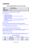
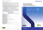
Ion Migration Evaluation System
AMI-U
CAT.NO.E08523
Analysis and evaluation of electrochemical
migration and evaluation of insulation resistance
made more accurate, efficient, and easier
Evaluations of electrochemical migration and insulation resistance are assuming
a greater degree of importance as electronic devices are
more and more miniaturized and mounted with higher density.
The
“Ion Migration Evaluation System”
allows these evaluations
to be performed continuously with a high degree of accuracy and efficiency.
Environmental testing has been successfully merged with measurements/evaluations.
1
AMI
2
AMI
ION MIGRATION EVALUATION SYSTEM
Makes stress evaluations and insulation resistance evaluations by
electrochemical migration efficient and easy, and covers a broad spectrum,
from low-voltage to high-voltage tests.
anode(+)
Cathode(−)
Main features
High precision measurement realized
●
by ESPEC's unique scanner operation
technology supported by continuous
power supply and international standardscompatible measurement equipment.
Stress constant voltage (stress voltage
and measurement voltage): 100V, 300V,
and 500V. (300V and 500V are optional)
Electrochemical migration accurately
identified in micro second by the Leak
Touch detection.
Real-time measurement enabled using
a personal computer. Editing/ browsing
of data available during the evaluation
process.
I mproved oper abilit y a nd safet y
achieved by the interaction with the
environmental test chambers.
●
●
●
●
Electrochemical migration between electrodes
(Electro photographic image taken with EPMA produced by JEQL)
Evaluation targets
Printed circuit boards
Insulation materials
Semiconductor materials
●
●
●
Main applications
Flux, Printed circuit boards, Resist,
Solder, Resin,
Conductive adhesive and other
materials related to printed wiring
boards and high-density mounting
BGA, CSP and other fine-pitch pattern,
IC packages
Organic semiconductor related
materials (Organic electroluminescence)
Capacitors, Connectors and other
electronic components and materials
Evaluation of hygroscopic property of
insulation materials
●
●
●
●
●
Example of AMI connected with a Highly Accelerated Stress Test System (HAST Chamber)
Models
100V, Stress constant voltage:
Not applied/ 1 to 100 V DC
300V, Stress constant voltage:
Not applied/ 1 to 300 V DC
500V, Stress constant voltage:
Not applied/ 1 to 500 V DC
●
●
●
3
Utility
Using an international standard traceable precision instrument
guarantees the most accurate and compatible measurement data.
We have always known how to
earn our customers’ confidence
AMI is equipped with highly reliable
measurement equipment and an ammeter
for micro-electric current both designed
to meet international standards. This, to
obtain most reliable measurement data.
We of fe r a c a l ib r at ion s e r v ic e t o
maintain the equipment’s accuracy.
(ISO / IEC 17025 compliant)
Measures a wide range of
insulation resistance
The unit measures insulation resistances
with high accuracy over a wide range
from 2×10³ to 1×10¹³Ω at the tip of the
measurement cable (3m). The scanner
board for the micro-electric current uses
an advanced cable arrangement in order
to avoid leakage current influences on
the printed circuit boards.
AMI
From low-voltage to
high-voltage tests available
The AMI offers three ranges of applied
voltage specifications, for a variety of
applications in many fields: for example
f r o m low d r iv i n g volt a ge d e v ic e
evaluation, to high-voltage automotive
device evaluation.
A constant stress voltage of 100V is
applied, though 300 V and 500 V are
available as additional options.
Multi-channel continuous
measurement accurately detects a
change in the insulation resistance
Continuously measuring the insulation
resistance on multi-channels while
applying voltage under a high-temperature
and high-humidity environment allows
an optimized detection of the decreasing
insulation resistance.
Measurement equipment (Keithley Instruments, Inc.)
Measurement Accuracy Distribution Chart
Distribution of measurement accuracy at end of measurement cable
Outside temperature: Room temperature
Measurement mode: Long
1.0×10¹³ Ω
±30% or more
1.0×10¹¹ Ω
±10%
±5%
1.0×10⁹ Ω
±3%
1.0×10⁷ Ω
1.0×10⁵ Ω
Measurement range: AUTO
Number of averaging measurements: 4
±5%
Measurement Not Possible
(Exceeds Current Limit)
1.0×10³ Ω
1.0×101 Ω
1V
20V
40V
60V
80V
100V
・ Values on boundary lines are either lower accuracy measurements or accuracy
measurements that cannot be measured.
・ The above measurement results are provided for the purposes of example.
You may not be able to obtain the above measurement accuracy results depending on
your system installation environment.
In such a small range (100fA to 5pA), interferences might appear during measurement.
4
Utility
Multifunction rack that pursues ease of use to improve the workability.
Uninterruptible
power supply
System control PC
Start button
Connection-unit
•Fixable on both right
and left sides
Control on 5ch and 25ch basis
A control evaluation is possible in each
module, independently from the other.
We offer two types of modules, 5-channel
and 25-channel.
Connection unit
•Placed inside the cabinet
when not in use
Installing the connection unit facilitates
the measurement cable connection. The
connection unit can be installed in front
of the rack, or either on the left or right
side of the rack according to the work
environment.
Connection-unit
storage space
High accurate measurement
Keyboard table
Storage space
System rack
AMI employs a single cable (positive
side) and a co-axial cable (negative side)
to restrict the influence of micro-noises.
T h e c i r c u i t r y of A M I k e e p s t h e
impedance remarkably low in order to
provide precise evaluations. Cables are
coated with Teflon, which guarantees
indisputable advantages in terms of
resistance to heat, humidity, and voltage.
SIR test coupon type IPC-B-24
and test board rack (optional)
SIR test coupon type IPC-B-24 and test
board rack conform to IPC-B-24 as
stipulated in ISO 9455-17 for efficient
SIR testing. The test board rack can
receive up to five PCBs, and allows
measurement of up to 20 channels.
Connectors (optional)
Connection unit
We offer connection jigs tailored to the
specimen as an option. Connection jigs
e a s e t h e c o n n e c t io n b e t we e n t h e
specimen and the cable and improve the
test efficiency.
Global environmental issues
Components are fixed with lead-free
soldering. Furthermore, power consumption
has been reduced by 24% (compared to
the previous model) in consideration of
global environmental protection.
5
SIR test coupon type IPC-B-24 and test board rack type A
(optional)
*except for purchased items such as PCs and
measuring instruments.
Utility
Tests simplified by the interaction of the measurement system
with various environmental test chambers.
Interaction with
the environmental test chambers
Real-time monitoring of
temperature and humidity
Temperature and humidity
delay-control function
Safety design guaranteed by
abnormality detection
Remote processing of
the test data (optional)
Example of AMI connected with a FreeAccess Environmental Chamber
6
Evaluation
AMI uses a measurement method for insulation resistance that meets multiple types
of test requirements; among others can be named the electrochemical migration
evaluation, insulation deterioration characteristics evaluation, and so on.
Electrochemical migration test
Insulation deterioration
characteristics testing
Example of results obtained from
the Ion Migration Evaluation System (AMI)
Insulation resistance variation characteristics of flux under
high-temperature and high-humidity conditions
Test conditions
Temperature and humidity condition
Stress voltage
Measurement voltage
Measurement intervals
: 40℃, 90%rh
: 50 V DC
: 50 V DC
: 0.5h
1.00E+13
Sample A
Sample B
Sample C
Resistance value (Ω)
1.00E+12
1.00E+11
Recovers to high resistance
value after insulation decline
No practical changes
1.00E+10
1.00E+09
1.00E+08
Insulation resistance
value decline drastically
to below 1MΩ
1.00E+07
1.00E+06
100 112
132
152
172
192
212
232
252
272
292
312
332
352
372
Test duration (hr)
In the example above, the Leak Touch occurs at 291.2 hours and at 311.8 hours
after the measurement starts.
*The above test results were obtained from the Ion Migration Evaluation System,
and processed under an excel format (spreadsheet software).
7
Evaluation
Continuous measurement
mode with stress voltage
W h e n t h e s t r e s s volt a g e a n d t h e
measurement voltage are equivalent,
you can perform time-saving test by
using this mode. It will use the stress
voltage as the measurement voltage,
without recharging by the measurement
voltage. The test period is defined as
the accumulated stressed time. The time
for measurement (charge and measure)
is not included in the test period.
One shot charge
To measure the insulation resistance,
the sample(s) must be charged before
measurement. The AMI will charge by
m o d u l e (e i t h e r 5 c h a n n e l s o r 2 5
channels) rather than one by one, this
allowing time-saving for testing.
Individual voltage supply per
channel
A channel with its independent power
supply guarantees no voltage weakening,
nor any leakage on other channels. Each
channel has also its individual voltage
monitor to insure the correct voltage is
applied to every channel.
Voltage migration image obtained by continuous
power supply scanner operation technology
●
Stress voltage (100V), measurement voltage (100V)
In the measuring mode of continuously applied stress voltage
Measurement
voltage
100V
100V
100V
Operating
condition
Stress voltage
applying period
Measuring period
Stress voltage
applying period
Stress voltage
●
Stress voltage (50V), measurement voltage (100V)
100V
Measurement
voltage
Stress voltage
Operating
condition
50V
Stress voltage
applying period
50V
Measuring period
Stress voltage
applying period
Voltage that is actually applied onto the specimen
Accumulated stress voltage applying time (test time)
No voltage disruption thanks to
a specially designed scanner
ESPEC designed scanner guarantees no
interruption of the applied voltage from
stress to measurement process. This is
made possible thanks to a control on the
voltage supply area. (same for stress and
measurement)
8
FAILURE RECOGNITION
There are two recognition methods for all kind of failure.
Limit recognition
Leak Touch detection recognition
By setting an absolute value, a
change rate (%), or changing the
amount.
These three failure criteria can be
used to set the threshold of your
test, on each channel.
■ “Leak Touch” detection and
With absolute value setting
With change rate setting
Reference values.
Resistance/Ω
In the case where a failure is detected
Detection of the leakage current
50%
Leak Current Value
100%
Time/h
Sets the initial resistance
measurement as a base value,
and thereafter recognizes failure
based on a percentage of the
initial value.
With Leak Touch detection setting
Resistance/Ω
●
Leak Touch behavior
detection record
End of the
measurement
Leak Touch behavior
detection mode
Time/h
Absolute value
●
In the case where the resistance value returns
to normal during behavior detection
Time/h
The Leak Touch detection and
recognition instantly detects leakage
occurences between samples, and
completes the measurement.
Resistance/Ω
Absolute Value:
Allows you to set an absolute
value at which the AMI will
recognize a failure.
9
This mode allows to catch the ion
migration, and observe the dendrites
that appears during conductances.
Measurement criteria can be set, such
as the failure detection threshold,
number of times for the detection or
else the recovery time.
(The leak current can be set between
1 and 500μA.)
Rate of change
Time/h
●
■ Leak Touch observation mode
●
Resistance/Ω
Resistance/Ω
●
recognition
μ
Detection of
the leakage
current
Leak Touch behavior
detection mode
The resistance
value returns to
normal
Measurement
resume
Time/h
Real-time detection point of
leakage current
(detection sensitivity 100µsec/ch)
SOFTWARE
●
Main window*
・Test monitoring
・Real time display of the resistance value,
temperature inside the chamber, channel on
which a failure occurs
・Auto link to the data processing software
・Control commands (start, stop, pause, and
restart)
* The picture shows AMI-075-U-5.
●
Test condition registration
Parameters:
・Test Duration setting
・Interval
・Measurement voltage
・Limit value...
Registration in a file.
●
Graphic display
Current test data and previous data are
displayed on graphs.
Graph can be arranged by selecting the
channel, display set ting, and cursor
display.
●
Test setting
On this screen, (image above),
test settings can be registered:
・Test module
・Files' names setting/ saving
・Interaction
(select the chamber which it works with)
・Text data output option
・Leak Touch detection mode...
●
Data display
Displays current test data and previous
data.
●
Test details
Select test channels and conditions.
(From test conditions already registered
in files)
●
Weibull Analysis (optional)
Data- proc es sing s of t ware (with a
statistical processing function) enables
Weibull analysis of test data, as well as
regular probability plotting, and
logarithmic probability trend curves.
10
SPECIFICATIONS
Type
Stress constant voltage 100 V
Channel configuration
Standard 25ch. (max. 150ch per rack)
Control channel
5ch
Measurement
Resistance evaluation and measurement time Stress power supply
Software
Min. set voltage
resolution
25ch
Not applied/ 1 to 500 V DC
0.1 V (1 to 100 V, individually able to set
from the measurement voltage)
0.1 V (set at 1 to 200 V)
1.0 V (set at 200 to 300 V)
0.1 V (set at 1 to 200 V)
1.0 V (set at 200 to 500 V)
500 µA to less than or equal to10 pA
0.1fA to 20mA (resolution: 0.1fA) *2
500 µA to less than or equal to10 pA
2×
to 1 ×
(when applying 100 V)
2 × 10³ to 1 × 10¹¹
(when applying 1 V)
105
2×
to 1 × 10¹³
(when applying 300 V)
2 × 10³ to 1 × 10¹¹
(when applying 1 V)
1013
±1.015% (20pA range, full scale)
1 to 100 V DC (0.1 V step)
15 sec.
+ charging time
80 sec.
+ charging time
2 × 10⁵ to 1 × 10¹³
(when applying 500 V)
2 × 10³ to 1 × 10¹¹
(when applying 1 V)
105
±1.015% (20pA range, full scale)
1 to 300 V DC
(1 to 200 V DC: 0.1 V step)
(200 to 300 V DC: 1.0 V step)
1 to 500 V DC
(1 to 200 V DC: 0.1 V step)
(200 to 300 V DC: 1.0 V step)
15 sec.
80 sec.
15 sec.
80 sec.
+ charging time + charging time + charging time + charging time
+side
Single cable
Heat-resistant single cable
−side
Coaxial cable (one-layer shield)
Coaxial cable (one-layer shield)
Type
Normal 100 µ sec / less than or equal to specified
number of detections on channel basis
Measurement cable
Leak Touch detection
Coated material
Normal 100 µ sec / less than or equal to specified number of
detections on channel basis
Teflon (heat resistance of + 150℃)
Teflon (heat resistance of + 150℃)
Length
Connects the scanner unit and connection unit: 2.5 m
Beyond connection unit : 1.5 m
Connection unit
25-channel connection
Coaxial connector
25-channel connection
+side: Metallic outlet −side: Square type coaxial connector
Model: 6514 (Keithley Instruments, Inc.)
Model: 6514 (Keithley Instruments, Inc.)
W530 × H1750 × D940 mm
W530 × H1750 × D940 mm
Measuring equipment
External dimension
Power supply facility
Connects the scanner unit and connection unit: 2.5 m
Beyond connection unit : 1.5 m
100 V AC, 1φ, 10.0 A
120 V AC, 1φ, 8.3 A
220 V AC, 1φ, 4.5 A
240 V AC, 1φ, 4.2 A
100 V AC,
120 V AC,
220 V AC,
240 V AC,
1φ, 10.0 A
1φ, 8.3 A
1φ, 4.5 A
1φ, 4.2 A
*1The measurement accuracy and the DC measurement range are only applicable to the measuring equipment.
For the measurement accuracy in the whole system, please refer to the Measurement Accuracy Distribution Chart on page 4.
A slight voltage drop may occur depending on the current flow through specimens. This voltage drop is not included in the applied voltage accuracy.
*2The connection unit for applied high voltage is equipped with 1 kΩ resistors in series on the positive side of the applied voltage.
*3The charging time will be zero in the stress voltage full-time measurement mode.
MODEL
ACCESSORIES
AMI - - U -
Measurement cable
Communication cable (RS-485)
Setup CD
User’s manual
●
Control channel
5 : 5-channel control
25 : 25-channel control
Number of channels
025 : 25 channels
050 : 50 channels
100 : 100 channels
125 : 125 channels
150 : 150 channels
●
●
●
AMI - - U -
11
25ch
Windows 7
0.1fA to 20mA (resolution: 0.1fA)
Measurement accuracy *1
5ch
Not applied/ 1 to 300 V DC
DC measurement range *1
Measurement
time (1 time) *3
5ch
Not applied/ 1 to 100 V DC
Applied voltage accuracy
Resistance
measurement
range
Stress constant voltage 500 V
(optional)
Standard 25ch. (max. 150ch per rack)
25ch
Windows 7
Stress constant voltage
Measurement
voltage
Stress constant voltage 300 V
(optional)
Control channel
5 : 5-channel control
System controller
Parallel I/O
Chamber monitor
Micro-current ammeter
GPIB
Uninterruptible
power supply
RS-232C
SYSTEM CONFIGURATION DIAGRAM
RS-485
Connection unit
Specimens
Scanner for
minute current unit
Scanner for minute current
Voltage monitor
Stress-application power supply
Leak detector
System rack
Environmental test chamber
(sold separately)
OPTION
Additional channel (25 channel basis)
Test board rack type A
LAN-compatible software
The channels can be added according to
the capacity of the system (150 channels
at maximum on 25 channels basis).
Test board rack for SIR test coupon
type IPC-B-24.
LAN-compatible software enables
remote test checking and data
processing, such as from a distant
office.
* License for multiple PC monitoring
requires an additional cost.
Additional Scanner Box
Required when adding a total of 100
additional channels or more.
Chamber cable
monitor
: connects the
Extended
that
Allows temperature
control,
monitoring,
scanner
unit and the
connection
unit
alarm control of chamber from system controller. SIR test coupon type IPC-B-24
Cables
can beammeter
lengthened
the
Micro-current
(0.1fAfrom
to 20mA):
standard
2.5 m. resistance of a specimen is Printed circuit boards that comply with
The insulation
measuredat
set intervals.
・1m
extended
IPC-B-24 specified in ISO 9455-17.
(Equipped with electrometer 6514 made
by Keithley Instruments, Inc.)
Measurement cable for 25 channel
(standard
type
1.5m)
Scanner for
minute
current unit
Scanner for minute current :
WeMeasurement
offer both positive
and25
negative
of standard
channels at
measurement
cables10in3Ωaddition
resistance value
to 1013Ω.to the
standard accessories.
Voltage monitor :
・1.5,
The 3m
output of each stress-application
Data processing software
(with statistical processing software)
We i b u l l a n a ly si s i s i n s t a l le d i n
addition to the standard statistical
processing software.
Communication cable
RS-485
5, 10m
Emergency stop switch
Stops the system immediately.
power supply is monitored.
Stress-application power supply :
Board holder
DC voltage is applied between specimen
poles as electric stress.
A power supply is provided for each channel.We offer a variety of jigs for securing
samples such as boards. (Connection
Leak detector :
terminal:
Constantly monitors leak current against pre-set
limit screw-type)
under applied stress voltage between electrode.
Connection unit :
Relays the measurement cable.
12
MEASUREMENT SYSTEMS
Conductor Resistance Evaluation System
AMR
Accurately detects minute cracks in semiconductor packages and
electronic component junctions. Automatic measurement and
chamber integration allow improved efficiency in test schedule
management.
■
Evaluation Targets
●
●
Printed circuit boards
Semiconductor underfill
Semiconductor Parametric Test System
AMM
Supports cutting-edge device evaluation and offers
highly-reliable data acquisition, collection, and analysis over
a wide range of evaluation conditions from reliability evaluations
to test/characteristic evaluations.
■
Evaluation Targets
●
●
●
Semiconductor transistors
Low-k materials
High-k materials
Electromigration Evaluation System
AEM
Space-saving all-in-one system, the AEM is the only product of
its kind in the industry to offer electromigration evaluation of
1μA at 400℃.
■
Evaluation Targets
●
●
Semiconductor wiring patterns
Solder bumps
Flash Memory Endurance Cycling System
RBM-LCT
A Monitored Burn-in System for evaluation testing of
non-volatile memory, such as Flash memory or FeRAM.
This testing/evaluation equipment is suited to a variety of
uses from R&D to mass production.
■
Evaluation Targets
●
13
Flash memory (FeRAM and MRAM)
VARIOUS ENVIRONMENTAL TEST CHAMBERS〈SOLD SEPARATELY〉
Temperature (& Humidity) Chamber
Platinous K Series
Model
Temperature range
PR
PL
PSL
PH
−20 to +100℃
Humidity range
−20 to +150℃
−40 to +100℃
−40 to +150℃
20 to 98%rh
Inside capacity (L)
120、
225、
408、
800
−70 to +100℃
−70 to +150℃
+10 to +100℃
306、
800
60 to 98%rh
120、
225、
408、
800
FreeAccess Environmental Chamber
Model
PFL-3K
PFL-3KH
Temperature range Humidity range Inside capacity (L)
−40 to +100℃
−40 to +150℃
20 to 98%rh
306
Bench-Top Type
Temperature (& Humidity) Chamber
Model
SH-221
SH-241
Temperature range Humidity range Inside capacity (L)
−20 to +150℃
−40 to +150℃
SH-261
−60 to +150℃
SH-661
−60 to +150℃
SH-641
−40 to +150℃
30 to 95%rh
22.5
64
Highly Accelerated Stress Test System
(HAST Chamber)
Model
EHS-211(M)
Temp./ humid./ pressure range
+105 to +142.9℃/ 75 to 100%rh
EHS-221(M) 0.020 to 0.196Mpa (0.2kg to 2.0kg/cm2)
EHS-411(M)
+105 to +162.2℃/ 75 to 100%rh
0.020 to 0.392Mpa (0.2kg to 4.0kg/cm2)
Inside capacity (L)
18
46
18
14
http://www.espec.co.jp/english
Head Office
3-5-6, Tenjinbashi, Kita-ku, Osaka 530-8550, Japan
Tel : 81-6-6358-4741
Fax : 81-6-6358-5500
ESPEC NORTH AMERICA, INC.
Tel : 1-616-896-6100 Fax : 1-616-896-6150
ESPEC EUROPE GmbH
Tel : 49-89-1893-9630 Fax : 49-89-1893-96379
ESPEC ENVIRONMENTAL EQUIPMENT (SHANGHAI) CO., LTD.
Head Office
Tel : 86-21-51036677 Fax : 86-21-63372237
BEIJING Branch
Tel : 86-10-64627025 Fax : 86-10-64627036
TIANJIN Branch
Tel : 86-22-26210366 Fax : 86-22-26282186
GUANGZHOU Branch
Tel : 86-20-83317826 Fax : 86-20-83317825
SHENZHEN Branch
Tel : 86-755-83674422 Fax : 86-755-83674228
SUZHOU Branch
Tel : 86-512-68028890 Fax : 86-512-68028860
ESPEC TEST TECHNOLOGY (SHANGHAI) CO., LTD.
Tel : 86-21-68798008 Fax : 86-21-68798088
ESPEC (MALAYSIA) SDN. BHD.
Tel : 60-3-8945-1377 Fax : 60-3-8945-1287
ESPEC CORP. has been assessed by and
registered in the Quality Management System
based on the International Standard ISO
9001:2008 (JIS Q 9001:2008) through the
Japanese Standards Association (JSA).
●
W6E20C03 (The contents of this catalog is as of June, 2008.)
●
ESPEC CORP.
Specifications are subject to change without notice due to design improvements.
Corporate names and trade names mentioned in this catalog are trademarks or registered trademarks.