1
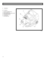
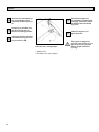
Apex 49
Model: PB40BL, PB40BH
User Manual
(Battery Version)
Introduction
Dear customer,
It is our desire that the good characteristics of the Apex 49 should
justify the confidence you demonstrated by making this purchase.
Before first operation of your Apex 49
read these instructions
carefully. The manual provides
valuable information about operation, service and maintenance.
Before first operation of the machine,
read these instructions and safety information carefully and comply with
them.
Please be advised explicitly that
we cannot accept any legal issues out of the contents of this
manual.
If repair work has to be performed make sure that only genuine spare parts are used; only
genuine spare parts may guarantee a dependable machine.
The symbol as used in this manual
identifies items relevant to safety.
Please observe the safety provisions (see chapter 1).
Valid as of:
2
March 2007
Proper Use
Proper Use
The Apex 49 sweeper has been
exclusively designed for collecting
dry and moist matter from floor surfaces in e.g. factories, storage buildings, parking ground and pedestrian areas. Using the machine
beyond this scope of application
will be deemed improper use; The
manufacturer cannot be held liable
for consequential damages.
The term of proper use also includes operation, maintenance and
repair work to be performed in compliance with the manufacturer's
specifications.
The Apex 49 may be used by personnel only that are familiar with the
machine and aware of possible
hazards involved.
The applicable Accident Prevention
Regulations, Road Traffic
Regulations, and aspects of safety
and working medicine in vigour will
have to be complied with.
If modifications to the machine are
made in absence of the manufacturer's prior consent, the latter cannot be held liable for damage resulting from such unauthorized modification.
The machine has not been
designed for collecting
dusts which are detrimental
to health or explosive.
parts or accessories without prior
and explicit consent or by non-compliance with the maintenance
instructions.
Notes on warranty
Inspection
The terms of the sales contract apply.
Damages are not subject to warranty
if they are due to non-compliance
with the maintenance and service
provisions. The maintenance work
has to be performed by an authorized
service center and confirmed in the
"Maintenance certificate" which is the
warranty document.
The following is excluded from warranty:
fuses, natural wear, damages caused
by overload, inexpert handling and
unauthorised modification of the
machine. Moreover, any claim for
warranty cannot be accepted if damages at the machine are caused by fitting
Carefully unpack and inspect your
Apex 49 for shipping damage. Follow
unpacking instructions on shipping
pallet. Each unit has been tested
and thoroughly inspected before
shipment. Any damage is the responsibility of the delivery carrier who
should be notified immediately.
3
Contents
Introduction/Proper Use
Notes on Warranty
Inspection
4
4.1
4.2
4.3
4.4
Operation . . . . . . . . . . . . . . . . . . . . .18
1
Safty Information . . . . . . . . . . . . .5
1.1
1.2
1.2.1
1.3
1.4
1.5
1.6
General Safety Information . . . . . . .5
Safety and Warning Symbols . . . . .6
Generally Applicable Symbols . . . .6
Labels at the Machine . . . . . . . . . .7
Operation/Safety Information . . . .10
Cleaning Informaton . . . . . . . . . . .11
Maintenance instructon . . . . . . . .12
4.5
4.5.1
4.5.2
4.5.3
4.5.4
4.5.5
Controls . . . . . . . . . . . . . . . . . . . .18
Control Panel . . . . . . . . . . . . . . . .20
Empty Dirt Hopper . . . . . . . . . . . .24
Empty Dirt Hopper
Lift-Up Disposal . . . . . . . . . . . . . .24
Working with the machine . . . . . . .27
Switch Electro-Motor ON and
OFF . . . . . . . . . . . . . . . . . . . . . . .27
Sweep . . . . . . . . . . . . . . . . . . . . . .28
Stop and Park . . . . . . . . . . . . . . . .28
Displace . . . . . . . . . . . . . . . . . . . .28
Transport . . . . . . . . . . . . . . . . . . .28
2
Description . . . . . . . . . . . . . . . . .14
5
Technical Data . . . . . . . . . . . . . . .29
2.1
2.2
2.3
2.4
2.5
2.6
2.7
2.8
2.9
2.10
Functional Descripton . . . . . . . . . .14
Cylinder Broom . . . . . . . . . . . . . . .15
Side Brush . . . . . . . . . . . . . . . . . .15
Filter System/Dust Evacuation . . .15
Shaking System . . . . . . . . . . . . . .15
Steering . . . . . . . . . . . . . . . . . . . .15
Wheels . . . . . . . . . . . . . . . . . . . . .15
Brake . . . . . . . . . . . . . . . . . . . . . .16
Travel Drive Assembly . . . . . . . . .16
Hydraulic System Lift-Up
Disposal . . . . . . . . . . . . . . . . . . . .16
6
Maintenance/Service . . . . . . . . .33
3
First Operation . . . . . . . . . . . . . .17
3.1
3.2
First Operation of Batteries . . . . . .17
Insert Batteries . . . . . . . . . . . . . . .17
6.1
6.2
6.3
6.4
Maintenance Instruction . . . . . . . .33
Mount/Dismount Cylinder Broom .34
Adjust Sweeping Track . . . . . . . . .34
Sealing strips for Broom
Compartment . . . . . . . . . . . . . . . .36
6.5
Folding Apron Adjustment . . . . . . .36
6.6
Replace Side Brush . . . . . . . . . . .37
6.7
Dismount Plate Filter . . . . . . . . . .38
6.8
Basic Cleaning of Plate Filter . . . .40
6.9
V-Belt Drive . . . . . . . . . . . . . . . . . .41
6.9.1 Replace Cylinder Broom V-Belt . .42
6.9.2 Replace Side Brush V-Belt . . . . . .42
6.9.3 Replace Suction Fan V-Belt . . . . .42
6.10 Adjust Steering Chain Tension . . .42
6.11
Check Hydraulic Fluid and Refill . .42
6.11.1 Check Hydraulic Fluid . . . . . . . . . .42
6.11.2 Refill Hydraulic Fluid . . . . . . . . . . .42
6.12 Electric System . . . . . . . . . . . . . . .43
6.13 Maintenance Schedule . . . . . . . . .44
7
4
Spare Parts . . . . . . . . . . . . . . . . .46
Safety Information
1
1.1
Safety Information
General Safety Information
Apart from the instructions contained
in this manual, the general safety
instructions and accident prevention
regulations, as imposed by law will
have to be complied with. Do not put
the Manual aside without reading it
even if you used similar sweepers
before. Take the time to read them
now and save time later. Machines
with known defects must not be used.
It will be of essence to make yourself
familiar with all accessories and controls and their functions before you
start working. Avoid the mess of
having to read this book while trying
to run the machine.
Using the machine in areas with
explosion hazard, on public roads
and places is prohibited.
The operator has to use the machine
within its design limits.
Shut the motors down before transporting the machine.
Keep clear of hazard zone!
Before commencing work, the operator has to make sure that the Apex 49
and its accessories are in proper and
safe condition.
Warning and instruction labels attached to the machine contain important information about safe operation.
Illegible or lost labels have to be
replaced.
Provide for sufficient
ventilation when sweeping
indoors (dust and
combustion gas).
Pinching and shearing hazard. Provide for required
safe distance before lifting
or lowering the dirt hopper.
Make sure that all covers
are fitted before starting to
sweep.
5
Safety Information
1.2 Safety and Warning Symbols
1.2.1Generally Applicable Symbols
All paragraphs in this manual referring to your personal safety, the safety of your machine and the environment protection are attributed one of
the following warning symbols:
Symbol
Hazardous for....
Description
DANGER
persons and
goods
dangerous situation
caused by misuse inaccurate adherence of instructions or
prescribed work routine
the machine
important information on handling the machine in order to
maintain operability
the environment
due to use of substances representing an inherent danger to
health of environment
CAUTION
Ecological hazard
6
Safety Information
1.3
Labels at the Machine
The following safety and information
signs are legibly attached to the
machine. Missing or illegible stickers
have to be replaced.
Read and observe operator's
Manual (7)
Key switch (8)
Brake (9)
Folding apron (1)
Noise power level (10)
82 dB (A)
Parking brake (2)
Nameplate
Powerboss/Apex 49 (3/4/5)
Fig.1
7
Safety Information
1.3 Labels at the Machine
24 V label (15)
Battery charging (16)
The label is located under the seat
hood.
Fig. 2 Safety and information
signs
8
Rotating parts (14)
Cylinder broom wearing take-up (12)
Safety Information
1.3 Labels at the Machine
Pinching hazard (6)
(Lifted-Up Disposal)
Hydraulic fluid (13)
High-pressure cleaner (11)
Do not clean by means of
high pressure cleaner or
vapour jet.
9
Safety Information
1.4
Operation/Safety
Information
Vacuum sweepers may be run by
qualified personnel only; such personnel will have to have evidenced
their qualification for running the
machine to the owner or his authorized representative; operators explicitly will have to be instructed by the
owner or his authorized representative to use the machine.
The machine may be used
for cleaning such surfaces
approved by the owner or
this authorised representative for operation of vacu
um sweepers.
Before starting the engine,
switch off all drives
Transporting persons on the machine
is prohibited. Ride-on machine types
are to be started with the driver being
seated.
10
Never leave the machine unattended
before the motors are off and the machine is protected against unintended
movements.
To prevent the machine from unauthorized use, pull the control key to block
all drives.
Shut down the motors before transport of the machine. The driver has to
take account of local conditions and
when operating the sweeper he has
to watch out for other persons, especially children.
Do not open hood or
fairings with the machine
running.
This machine must not be
used as dust-evacuating
machine with dust filter insert (separator) to collect
dusts which are hazardous
to health.
Compared to four-wheeled
vehicles, driving stability of
three-wheeled vehicles is
reduced. We thus recommend:
- do not negotiate curves at
high speed.
- do not turn at slopes but
on level ground only
- ride up- or downhill
straight.
Safety Information
Warning and instruction labels attached to the machine contain important information about safe operation
Provide for sufficient ventilation when sweeping indoors (dust and combustion
gas).
Proceed to filter shaking only if the dirt hopper is in closed position.
1.5
Cleaning Information
The machine is splash-proof (IPX3).
Do not clean the SW5X by
means of high pressure cleaner or vapour jet.
Proceed to cleaning of the
dirt hopper in regular intervals to preclude formation of
bacterial deposits.
11
Safety Information
1.6 Maintenance Instructions
A good approach to prevention of
accidents is proper maintenance of
the machine.
Before proceeding to repair or maintenance work remove the key.
Use appropriate tools for maintenance, service, setting etc.
As far as aspects of safety are concerned, spare parts will have to be at
least of the same quality as the genuine spare parts.
Switch off the motors before maintaining the machine
or replacing parts of it. Turn
off the machine and pull the
key and additionally, disconnect the battery plug.
Check hydraulic hoses and
lines for leakage or damages in regular intervals. Replace defective hoses and
lines immediately.
12
Before changing wheels
protect the machine against
rolling by placing wedges.
Proceed to wheel changing
when the machine is on level and solid ground.
Do not repair the pneumatic
tires mounted to the machine yourself. Dismount the
wheel and take it to repair to
a tire workshop.
Use of other than the cylinder brooms and side brushes approved by the manufacturer is not acceptable
(see technical data) since
use of other cylinder
brooms and side brushes
may affect your safety.
When handling lubricating agents, the applicable regulations for
protection of the environment and prevention of fire have to be
complied with. Provide
for disposal of used oil
and grease in accordance with the provisions imposed by law.
Collect cleaning
agents, oil, fuel oil, grease etc. and provide for
adequate disposal. Wipe away spilled substances.
Safety Information
Before commencing any
work on the electric system
disconnect battery (neg. lead) of the Apex 49 and pull the
ignition key.
Open the hood before charging batteries; explosive gases may occur during the
charging procedure.
Do not keep batteries discharged for a longer period;
always recharge them as
soon as possible.
Keep batteries dry and clean and clear of soiling such
as e.g. metallic dust to avoid leakage current.
Top with distilled water only. Never refill battery acid
in battery cells of perfect
condition.
Do not place metal objects
or tools onto batteries.
Short-circuit and deflagration hazard.
Battery acid is highly
caustic (keep clear of
children).
When checking the battery
acid level, wear safety glasses. If acid splashes get into the eyes rinse with clear
water for 15 minutes and
contact a doctor immediately.
Use appropriate protective
means (e.g. protective gloves or finger-stalls) when
handling battery acid.
Do not use open flames
(explosion hazard).
Spilled (straight) battery
acid must not get into the
sewage system before having been neutralised. Comply with the regulations imposed by law and observe
local provisions.
Do not eat, smoke or drink
in rooms where batteries
are charged to avoid damaging your health. After work
with batteries wash your
hands thoroughly. Provide
for sufficient ventilation.
13
Description
2
The side brush is used to collect dirt
at borders and to enlarge the working
width as well as to increase the area
performance on large surfaces.
The cylinder broom casts the debris
overhead into the dirt hopper. The collected fine dust is evacuated by the
suction fan and separated by a filter
system. The air returned into the environment is clean.
Description
2.1 Functional Description
Fig.4
Principle Model: PB40BH
Fig.3
Principle Model: PB40BL
14
Description
2.2 Cylinder Broom
The cylinder broom is equipped with
12 rows of bristles arranged in
V-shape.
The cylinder broom width amounts to
27.6 in. (700mm) and its diameter to
13.6 in. (345mm).
2.3 Side Brush
At the standard version, the side
brush is located at the front right of
the machine. The operator lifts and lowers it by hand lever.
The side brush has a light inclination.
The swinging area of the side brush
arm is limited by stop screws.
The side brush is driven by V-belt.
For special application, fitting of a
second side brush at the left is possible.
2.4 Filter System / Dust
Evacuation
The filter system is located in the filter case above the dirt hopper. The
suction fan transports the fine dust
raised by the cylinder broom to the
plate filter where it is separated. The
fine dusts sets at the outsides of the
filter blades.
2.6 Steering
Steering is controlled mechanically
from steering wheel to front wheel via
chain. This chain is to be re-adjusted
as required.
2.7 Wheels
Front wheel: solid rubber tires
Rear wheels: solid rubber tires
In case of heavy dust development, check and clean
the plate filter at regular
intervals.
2.5 Shaking System
Due to normal working vibration the
set dust partly falls off into the dirt
hoper. To ensure working in a dustfree environment, however, actuate
the shaking system regularly, or after
request by the pilot lamp at the latest.
15
Description
2.8 Brake
The Apex 49 is equipped with a service
brake.
This brake has been constructed as
shoe brake and equally serves as
parking brake.
It is located in the rear wheels and is
actuated via cables.
A special adjustment screw is situated at the right-hand rear wheel.
Any work at the braking
system has to be executed
by qualified persons in a
qualified workshop only.
2.9 Traction Drive Assembly
The Apex 49 is equipped with an electric
drive assembly with continuous regulation.
2.11 Battery Systems
Battery Charging Status Indicator
Before commencing any
work on the electric system
disconnect the battery plug.
Do not use open flames
when handling batteries and
especially when checking
the battery acid level. Provide for sufficient ventilation
in rooms where batteries
are charged. Spilled
(straight) battery acid must
not get into the sewage
system before having been
neutralised.
Comply with the regulations
imposed by law and observe local provisions.
Open the hood before charging batteries; explosive gases may occur during the
charging procedure
2.11.1 Low Discharge Signal
Sender
Setting Other Battery Types
Have the low discharge signal sender set to other battery types by qualified personnel only and in
approved qualified workshops only.
2.10 Hydraulic System
(Lift-Up Disposal)
The hydraulic system comprises a
compact unit (hydraulic pump with
hydraulic tank), the hydraulic hoses
and a hydraulic cylinder.
Hydraulic fluid: Mobil oil DTE 15 M
The named hydraulic fluid has been
filled in the hydraulic system in the
factory.
Filling of hydraulic tank: 0.2 gal. (0.76
litre).
2.11.2 Hourmeter
The operating hours of the machine
appear in the display (Fig. 5/2); the
hourmeter will count only during working or transport ride; only full hours
are displayed).
Fig. 5
16
Upon turning ON by key switch, battery charging status is shown by display of green bars (Fig. 5/1). As the
battery discharges during operation,
the lighting green bars extinguish one
after another showing thus always the
current charge status of battery charge.
Flashing of the last two green bars
indicates that operation will be stopped soon. In order to preclude low
discharge of batteries, the sweeping
units are switched off and riding
speed reduced to 50% if battery is
discharged. The red LED (Fig. 5/4)
than flashes.
First Operation
3
First Operation
3.2
Insert Batteries
If the battery type setting at
the LDS should be incorrect, have the setting modified by qualified personnel
in an approved workshop.
The Apex 49 has been extensively
tested and submitted to a functional
check before delivery.
Only qualified personnel of your local
contract dealer are allowed to proceed to first operation. After shipping
of the machine, we advise your contract dealer. He will contact you to
make a date for briefing lessons.
Use admitted lifting and
transport devices. Make sure that lifting hooks do not
damage cells, connectors
or connecting cables.
3.1 First Operation of Batteries
To achieve the optimum performance
and a maximum service life, the batteries must be given the initial charge
after filling.
Handling and function of the battery
charger is described in detail in the
instruction manual supplied with each
charger unit.
Since batteries and charger
units are matched, we recommend using batteries
and chargers as prescribed
by Minuteman. We can
grant full warranty only if
those units are being used.
Do not use the Apex 49 at ambient temperatures of more
than 105°F (40°C).
Do not start the machine at
temperatures of 32°F (0°C)
or less.
Fig.5a
- Turn machine off and pull key.
- Secure machine by actuating parking brake.
- Fold up seat hood
- Insert battery
- Connect charging plug of the battery connection cable and cable of
the charger unit and proceed to initial charging.
- After charging of the batteries, connect charger plug (Fig.5b/2) and
device plug for electrical connection.
Fig.5b
17
Operation
4
Operation
4.1 Controls
1
2
3
4
5
6
7
Actuator for folding apron
Service brake lock
Service brake/parking brake pedal
Drive pedal, reverse
Drive pedal, forward
Control panel
Seat adjustment
Fig.6
18
Operation
1 Actuator for folding apron
to open and close the folding apron
for collecting coarse dirt.
2 Service brake/parking brake lock
to lock the service brake/parking
brake. If locked, the service brake
works as parking brake. Release
the lock by depressing the service
brake pedal.
3 Service brake/parking brake pedal
to actuate the service brake at the
rear wheels. Before leaving the machine unattended, engage the service brake and lock.
4 Drive pedal, reverse
to change direction to reverse ride
with continuous regulation of riding
speed at the same time. If the driver releases the pedal it returns to
initial position and the machine
slows down to standstill.
5 Drive pedal, forward
to change direction to forward ride
with continuous regulation of riding
speed at the same time. If the driver releases the pedal it returns to
initial position and the machine
slows down to standstill.
6 Control panel
Refer to chapter "Control panel"
7 Seat adjustment
to adjust the seat position to drivers
of different height.
Adjust the seat so as to allow the
driver being comfortably seated and
attaining all elements required for
operation.
- Adjust seat lengthwise: push lever
slightly to the right and displace seat forwards or backwards to the required position. Then let the lever
catch again.
19
Operation
4.2 Control Panel
1 Cylinder broom lever
2 Release of lifted-up disposal function
3 Horn
4 TSG
5 Suction fan/shaking system knob
6 Flashlight (option)
7 Lighting (option)
8 Lift and lower (Lift-Up Disposal)
9 Side brush lever
10 Pilot lamp, parking brake
11 Battery charge status indicator/
Hourmeter
12 Pilot lamp, fan
13 Pilot lamp, shaking system
14 Key switch
Fig.7
20
Operation
1 Cylinder broom lever
to lift and lower as well as to
switch on and off the cylinder
broom and the side brush.
- Lower cylinder broom as well as
switch on cylinder broom and side
brush
= push lever
- Lift cylinder broom as well as switch
off cylinder broom and side brush
= pull lever
2 Release for lifted-up disposal
function
to release the lifted-up disposal
function for lowering of lifting.
Has to be actuated before
pressing the key for
lifting/lowering lifted-up disposal function. Hold the key
during lifting/lowering.
Before changing lifting to
lowering or vice versa, the
"Release Lifted-Up Disposal" key has to be released
once and pressed again
3 Horn
An acoustic signal sounds upon
actuation of this button.
4 Cover with plug connection for
battery/LDS programming
Remove this cover to modify setting
of battery type. The plugged connections of the programming cable are
located there.
Have the programming executed by a contract dealer
with qualified personnel at
hand.
21
Operation
After jolting, the knob is to
be kept in position 1 for about 10 seconds (to optimize
the cleaning result in case
of heavy fine dust load).
5 Suction fan/shaking system
knob
If the yellow pilot lamp (Fig. 7/13)
lights, actuate the shaking system
(position 2).
In this position, the shaking system is
operable and proceeds to jolting in 7
repeated intervals.
Knob position (from bottom to top
position):
Pos. 0
Activated vacuuming
function (close flap before sweeping dry surfaces or collecting dry
dirt).
6 Flashlight (option)
to switch the flashlight ON/OFF.
Pos. 1
Deactivated vacuuming function (open flap before
sweeping wet surfaces and collecting wet dirt).
Pos. 2
Shaking system ON
(pull knob to stop and then
release)
7 Lighting (option)
to switch the driving headlight
ON/OFF.
22
Operation
8 Lift and lower (lifted-up disposal)
to lift and lower the dirt hopper.
Lift the dirt hopper by pressing the
key until the desired height for lifting-out is attained.
When lowering the dirt hopper make sure to hold the key pressed
until the hopper has contact with
the frame.
10 Pilot lamp, parking brake (red)
lights upon actuation of the parking brake Extinguishes upon
release of the parking brake.
11 Battery Charging Status Indicator
Refer to paragraph 2.11
Hourmeter
Refer to paragraph 2.11
Actuate release key for lifted-up disposal and hold
before lifting or lowering.
13 Pilot lamp, shaking system (yellow)
Proceed to jolting of the filter
system upon lighting of this pilot
lamp by actuating the knob
(Fig.7/5).
The pilot lamp flashes during the shaking procedure
and extinguishes after filter
has been cleaned. Jolting is
effectuated in 7 intervals.
12 Pilot lamp, suction fan (orange)
lights if the suction fan is not activated.
9 Side brush lever
to lift and lower the side brush.
- Lower side brush
14 Key switch
to switch ignition on and off, to
start and stop engine and to secure it against unauthorised use.
= push lever
- Lift side brush
= pull lever
23
Operation
4.3 Empty Hopper
- Fold bow (Fig. 8/3) up
= the dirt hoppers (Fig. 8/2) are lowered.
- Use the recessed grip (Fig. 8/1) of
one of the hoppers to lift it lightly
and extract it.
- Take the hopper at its bow-type
handle to disposal and empty.
- Empty second hopper as described above.
- Re-insert hopper (Fig. 8/2) and
fold down the bow (Fig. 8/3).
1 Recessed grip in hopper
2 Dirt hopper
3 Bow to lift/lower dirt hoppers
Clean hoppers at
regular intervals.
4.4 Empty Hopper (Lift-Up
Disposal)
Lift side brush and cylinder
broom before emptying of
the hoppers.
Broom and fan will be autmatically switched ON upon
lowering of the hopper if cylinder broom has been ON
before lifting.
Fig.8
24
The driving speed forward
and backwards with dug
turning property container
is reduced to 50 %, the turning roller is switched off.
Fig.9
1
2
3
4
Lift-out arm
Lift-out cylinder
Hopper
Bow-type handle
Clean hopper at regular
intervals.
Operation
Lift side brush and cylinder
broom before removal of
the dirt hopper.
Pinching and shearing hazard. Provide for required
safe distance before lifting
or lowering the hopper.
Riding with the lifted hopper reduces stability of the
machine significantly. For
this reason, do not lift the
hopper but just before emptying. Before lifting the hopper, the operator has to make sure that no persons or
objects are behind or next
to the machine. Stop the
machine on level ground
before lifting the hopper.
Proceed to emptying of the
hopper as follows:
-
When the hopper is lifted,
the operator has to ride the
machine slowly.
Fig.10
Lift and switch off side brush and
cylinder broom
Proceed to shaking of the filter
system
Actuate switch (Fig. 10/1) and hold
(hopper is released)
Actuate switch (Fig. 10/2) by
pushing = lift hopper
Hopper (Fig. 9/3) is lifted-out
Back the Apex 49 until the hopper is positioned above the container for disposal.
Pull the safety knob (Fig. 11/1) of
the release lever (Fig. 11/2).
Release swinging of the hopper
by release lever (Fig. 11/2).
Forward the Apex 49 after emptying.
Lower hopper by actuating
switch (Fig. 10/1) and switch (Fig.
10/2); pull lever = lower hopper
Control panel (Lift-Up Disposal)
Keep clear of the hazard
zone!
1 Release switch for lifted-up disposal function
2 Hopper, lift and lower
25
Operation
Should the hopper not
be completely emptied after
swinging, proceed to manual shaking with the handle
(Fig. 9/4).
Observe the information given in paragraph 4.2 on
releasing of lifted-up disposal.
Sweeping is possible only
after the hopper has attained its working position.
Clean the hopper in regular intervals.
Lifted-up disposal function
is blocked as long as sweeping function is ON.
Fig.11
Release lever, swing hopper
1 Safety knob
2 Release lever, swing hopper
26
The hopper is approved
only for a max. filling of 18.5
gal (70 litres) but not more
than a weight of 242.5 lb
(110 kg).
Operation
4.5 Working with the machine
4.5.1 Switch Electro-Motor ON and
OFF
The driver is requested to carefully
read this manual. All controls are
marked with easy-to-understand symbols that ease familiarization. First
driving attempts should be limited to
clear areas until you are familiar with
all controls and their functions.
Please comply with the following safety provisions:
When working with the Apex 49
all safety measures
generally applicable for
handling vehicles have to
be observed. No passenger
transport is admitted with
the Apex 49. Warning and in- struction labels attached to
the machine contain important information about safe
operation and guarantee
your personal safety. Before
commencing work, the operator has to make sure that
the machine and its accessories are in proper and safe condition and comply
with the provision for safety
at work. Do not operate the
Apex 49 without protective
devices.
For safety reasons, the Apex 49
is equipped with a
seat contact switch. Starting the motor or running
the motor is possible only
when the driver is seated. If
the seat contact switch is
activated with the electromotor running, reset by turning the key switch OFF
and ON again.
Switch all levers and switches to
neutral position.
Actuate parking brake
Turn key switch to "I"
Check the drive pedal for
being in neutral position before switching ON.
If the Apex 49
is not used within the admissible conditions and environments of use, the protective functions may
respond and switch off driving function without prior
warning.
Slow the machine down to
standstill by the service brake in that case.
Acknowledge protective
function by key switch.
Overheating of the travel
drive assembly or control
module always entails a
cooling phase.
The seat contact switch deactivated all functions, driving function included.
Slow the machine down to
standstill by the service brake in that case.
27
Operation
4.5.2 Sweep
4.5.4
- Lower cylinder broom.
- Release parking brake.
- Slowly depress drive pedal until
desired speed has been attained.
- Regularly actuate shaking device to
clean plate filter.
- Check filling level of the hopper
and empty if required.
Make sure that the key switch is in
neutral position and the side brush
and cylinder broom are lifted up before displacement of the machine.
4.5.3 Stop and Park
- Release drive pedal which returns
automatically into its neutral position and the machine slows down to
standstill.
- Actuate parking brake
- Lift side brush and cylinder broom
- Turn key switch to "0"
When leaving the machine
unattended, pull key in order to preclude unauthorized use.
28
Displace
4.5.5 Transport
Before transporting the machine on
other vehicles, engage the parking
brake and secure the machine by
straps and by placing wedges at the
wheels.
Technical Data
5
Technical Data
Apex 49
Dimensions and weights
Length with side brush
Width without side brush
Width with 1 side brush
Width with 2 side brushes
Height above driver's seat
Max weight including accessories
Admissible total weight
Driving and sweeping performance
Forward speed
Reverse speed
Sweeping speed up to (4 km/h recommended)
Sweeping track without side brushes
- with 1 side brush
- with 2 side brushes
Theoretical sweeping perf. without side brushes
- with 1 side brush
- with 2 side brushes
Gradability, max.
Apex 49(Lift-Up Disp.)
in. (mm)
in. (mm)
in. (mm)
in. (mm)
in. (mm)
lb (kg)
lb (kg)
59.8 (1520)
39.4 (1000)
44.1 (1120)
48.8 (1240)
51.2 (1300)
1323 (600)
1742 (790)
59.8 (1520)
39.4 (1000)
44.1 (1120)
48.8 (1240)
51.2 (1300)
1367 (620)
1830 (830)
mph (km/h)
mph (km/h)
mph (km/h)
in. (mm)
in. (mm)
in. (mm)
sq. ft./h (m² / h)
sq. ft./h (m² / h)
sq. ft./h (m² / h)
%
3.7 (6,0)
2.5 (4,0)
3.7 (6,0)
27.6 (700)
28.2 (970)
48.8 (1240
45210(4200)
62430(5800)
80190(7450)
16
3.7 (6,0)
2.5 (4,0)
3.7 (6,0)
27.6 (700)
28.2 (970)
48.8 (1240
45210(4200)
62430(5800)
80190(7450)
16
29
Technical Data
Apex 49
Filter system
Filtering surface
Hopper filter
Cylinder broom
Length
Diameter
Wearing limit
Speed
Sweeping track
Quantity of bristle rows
Serial bristling
Ground clearance of Rubber Skirts at broom
compartment
Rubber Skirts
- left
- right
- rear
Skirt front
Side brushes
Diameter
Speed
Serial bristling
Hopper
Hopper capacity
30
Apex 49 Lift-Up Disp.
sq. ft. (m²)
piece
30.1 (2,8)
1
30.1 (2,8)
1
in. (mm)
in. (mm)
in. (mm)
rpm
in. (mm)
27.6 (700)
13.6 (345)
11.4 (290)
530 +/- 20
2.0 + 0.2 (50+5)
12 v-shape
PES
27.6 (700)
13.6 (345)
11.4 (290)
530 +/- 20
2.0 + 0.2 (50+5)
12 v-shape
PES
in. (mm)
in. (mm)
in. (mm)
0.04 (1)
0.04 (1)
0.16 (4)
0.04 (1)
0.04 (1)
0.16 (4)
in. (mm)
rpm
460
90
PES
460
90
PES
gal (l)
2x7.9 (2x30)
18.5 (70)
Technical Data
Apex 49
Tires
Front drive wheel, bandage
Rear, solid rubber tires
Electric drive
Service voltage
Travel drive assembly (P2/P1)
Suction fan motor/sweeping (P2/P1)
Total power consumption (P1)
Apex 49(Lift-Up Disp.)
in. (mm)
in.
11.81 (300/90)
4.00 - 4
11.81 (300/90)
4.00 - 4
DC/V
KW
KW
KW
24
0.8/1.0
1.0/1.25
2.4
24
0.8/1.0
1.0/1.25
2.4
Hydraulic system
Compact unit (maintenance-free)
Voltage
V
DTE 15 M or
equivalent
Hydraulic fluid, e.g.
Hydraulic tank, capacity
24
gal (l)
0.2 (0,76)
31
Technical Data
Noise emission
The sound pressure level measured according to DIN EN
ISO 11201 and under standard operating conditions at the
operator's ear with
- operating status
- fan, cylinder broom and side brush ON amounts to
dB (A)
70
The sound power level measured according to DIN EN
ISO 3744 under standard operating conditions and maximum volume flow amounts to
dB (A)
82
Vibrations
The frequency weighted acceleration measured according
to EN 1003 which have an effect upon the upper limbs
(hand-arm-system) amounts under normal working conditions
ft./s2 (m/s2)
< 8.07 (< 2,5)
The frequency weighted acceleration measured according
to EN 1032 which have an effect upon the lower limbs
(feet and seat) amounts under normal working conditions
ft./s2 (m/s2)
< 1.64 (< 0,5)
32
Maintenance/Service
6
Maintenance/Service
6.1 Maintenance Instructions
Compliance with our recommendations concerning maintenance work
will give you the certitude of having
an effective and dependable machine
at your disposal.
It is better to take precautions than
repairing damages - and it saves
money!
The Apex 49 has to be inspected for safe condition by an
authorized expert as required, but not less than once
a year.
Results of such an inspection have to be kept on file
at least until the next inspection is performed.
Please contact your local distributor if
you cannot do the maintenance
works as prescribed in the maintenance schedule in-house. He will
have these works done for you and
has qualified personnel and genuine
spare parts at disposal.
When cleaning or servicing
the machine, or replacing
parts, have the motors stopped and the key removed,
the negative battery pole
disconnected and the service brake (parking brake)
engaged.
In case of questions or orders for
spare parts, please always quote your
machine's serial indicated on the
nameplate
Refer to chapter 1.3.1 Fig. 2/12 for
position of nameplate.
Collect spilled oil and
provide for adequate
disposal.
Use appropriate tools for
servicing, maintenance and adjusting
work only.
Spare parts at least will have to be of
the same quality as genuine parts
are.
Do not remove or install tires or repair a rim. Take the
wheel and rim to a workshop where qualified personnel and the required specific tools are available.
When working at the electric system disconnect the
negative pole of the battery.
33
Maintenance/Service
6.2 Mount/Dismount Cylinder
Broom
The cylinder broom is accessible
from the left side of the machine and
is to be dismounted as follows:
- Open locks (Fig. 14/2) by enclosed
square spanner (turn counter-clockwise)
- Remove cover (Fig. 14/1)
- Lower cylinder broom
- Pull ignition key and protect by engaging parking brake
- Remove cover
- Turn handle (Fig. 15/3 +5) upwards
and unlock
- Remove plate with sealing strip
(Fig. 15/4)
- Remove cylinder broom by pulling.
For mounting the cylinder broom proceed in inverse order.
6.3 Adjust Sweeping Track
An adjustment device allows adaptation to different sweeping conditions.
The cylinder broom has to be
adjusted for normal use and with
regard to a low degree of wearing as
described in the following.
Check the broom adjustment on level
ground as follows.
Fig.15
Dismount cylinder broom
Remove cover
34
Fig.14
- Loosen star-shaped knob (Fig.
15/2) and remove
- Remove cylinder broom seating
(Fig. 15/1)
Maintenance/Service
With one full turn of the
knob, the track widens or
broadens by approx.
0.4 in. (10 mm)
Before checking:
Mark level surface for checking broom adjustment by
chalk.
When exceeding the sweeping track width the cylinder broom wearing increases as well as the load of
the drive.
- Secure machine by engaging parking brake.
- Lower cylinder broom and let it run
dry.
- Lift cylinder broom and forward the
Apex 49 a bit.
With the correct broom adjustment
the parallel sweeping marks have
to appear on the floor (sweeping
track).
The sweeping track width is to be
1.97 in. (50mm) with the Apex 49
The sweeping track width can be
adjusted at the star-shaped knob
(Fig. 15/2) as follows:
Broom adjustment
Fig.16
-
Stop engine and pull key
Engage parking brake
Open seat hood
Loosen handle (Fig. 16/3)
Turn star-shaped knob (Fig. 16/1)
to the left = wider sweeping track
to the right = smaller sweeping
track
- Fix handle (Fig. 16/3)
- Broom adjustment sticker (Fig.
16/2)
Fig.17
Fig. 17 Broom adjustment
sticker (in Fig. 17/2)
35
Maintenance/Service
6.4 Rubber skirts for Broom Compartment
In order to assure good function of
the sweeper, excellant maintenance of
the skirts is required, especially
in order to attain the prescribed
low pressure in the broom compartment, a clean sweeping result and
the less possible wear of the skirts
(check the Rubber skirts @ the
broom compartment for wear and
damage in regular intervals).
Replace defective skirts.
The ground clearance of the lateral
and rear skirts is adjustable via
(oblong holes in the skirts).
Ground clearance
sides: approx. 0.04 in. (1mm)
rear: approx. 0.16 in. (4mm)
Height of the front skirt (folding apron)
cannot be adjusted.
Being dragged, it has contact with the
floor.
36
6.5 Folding Apron Adjustment
- Remove bolt (Fig. 18/2).
- Modify adjustment by turning the
fork head (Fig. 18/1).
Modify adjustment such
that the cylinder broom
does not retract the sealing
strip of the folding apron
during operation.
Fig.18
Adjust folding apron
- Turn engine off and pull key
- Secure machine by engaging parking brake
- Remove cover (as described in the
paragraph "Mount/Dismount Cylinder Broom").
Maintenance/Service
Proceed in inverse order for mounting
of the side brush.
6.6 Replace Side Brush
The side brush is located at the front
right of the machine (standard version). Use the lever (paragraph 4.2,
Fig. 7/9) to lift and lower the side
brush.
The side brush is to be lightly inclined
in forward and in outward direction.
The swinging area of the side brush
arm is limited by stop screws.
The side brush is driven by a V-belt.
Fitting of a second side brush for
specific appliances is possible.
Proceed as follows for dismounting of
the side brush:
Replace side brush
Fig.19
- Turn engine off and pull key.
- Secure machine by engaging
parking brake
- Disconnect battery plug
- Side brush lifted
- Loosen hexagonal nut (Fig. 19/1)
und remove together with washer
- Remove screw (Fig. 19/2)
- Remove side brush
37
Maintenance/Service
6.7 Dismount Plate Filter
Proceed as follows for dismounting of
the plate filter:
- Turn engine off and pull key.
- Secure machine by engaging
parking brake
- Disconnect battery plug
- Open seat hood
- Open quick-release locks (Fig.
20/1)
- Remove cover, filter case (Fig.
20/2)
- Loosen wing screws (Fig. 21/2) and
remove.
- Fold back frame with electric-motor
(Fig. 21/3).
- Hook frame at indicated position
(Fig. 21/4)
- Remove plate filter (Fig. 21/5).
For mounting of plate filter proceed in
inverse order.
38
Fig.20
Dismount plate filter
1 Quick-release locks
2 Cover of filter case
3 Filter case
Maintenance/Service
Fig.21
Hopper filter
1
2
3
4
5
Detent hook
Wing screws
Frame with electric-motor
Opening for detent lever
Hopper filter
39
Maintenance/Service
6.8 Basic Cleaning of Hopper Filter
Hold the Hopper filter (Fig. 22/1) in vertical position and drop it from a height
of approx. 3 ft. (1 m) to the even floor
as represented in Fig. 22.
The dirty side of the filter
points to the bottom.
Soiled side
Clearance approx. 3ft. (1 m)
Floor
Fig.22
Basic cleaning of Hopper filter
1. Hopper filter
40
Maintenance/Service
6.9 V-Belt Drive
1
2
3
4
5
6
7
8
9
10
11
12
13
Tension roller
Suction fan V-belt (20Hz)
V-belt pulley
V-belt for cylinder broom and side
brush (130Hz)
Side brush V-belt
Belt pulley
Cylinder broom V-belt
Tension roller lever
Belt pulley
Tension spring
Hexagonal nut
Hexagon socket screw
Screws
V-belt drive
Fig.24
41
Maintenance/Service
6.9.1 Replace Cylinder Broom VBelt
- Turn engine off and pull key.
- Secure machine by engaging
parking brake.
- Disconnect battery plug
- Detent tensioning spring (Fig.
24/10) by left hand while taking the
V-belt off the tensioning roller with
right hand.
- Remove V-belt (Fig. 24/7).
Proceed in inverse order for mounting.
6.9.2 Replace Side Brush V-Belt
- Turn engine off and pull key.
- Secure machine by engaging parking brake
- Disconnect battery plug
- Remove bottom right cover (turn
locks counter-clockwise by square
spanner).
- Remove cylinder broom V-belt (as
described in paragraph "Replace
Cylinder Broom V-Belt")
- Loosen screws (Fig. 24/13) at the
cover plate and remove
- Remove cover plate
- Push side brush from the front side
in direction of the machine to detent
V-belt (Fig. 24/5)
- Remove V-belt (Fig. 24/5)
Proceed in inverse order for mounting.
6.9.3 Replace Suction Fan V-Belt
- Turn engine off and pull key.
- Secure machine by engaging parking brake
- Open seat hood
- Disconnect battery plug
- Open quick-release locks (Fig.21/1)
- Remove filter case cover (Fig.21/3)
- Loosen screws at the inside of the
right lateral fairing and remove.
- Tilt lateral fairing lightly to the outside, the remove by pulling upwards.
- Loosen tensioning roller (Fig. 24/1)
- Loosen hexagonal nuts (Fig. 24/11)
and hexagon socket screw
(Fig.24/12).and detent V-belt
(Fig.24/4)
- Remove V-belt (Fig.24/4) from Vbelt pulley (Fig.24/3).
- Remove V-belt (Fig.24/2).
Proceed in inverse order for mounting. Do not exceed tension of V-belt.
Observe the following when
mounting the V-belt: First
adjust tension of V-belt
(fig.24/4), then adjust tension of V-belt (fig.24/2).
6.10 Adjust Steering Chain Tension
Check the condition and function of
steering chain every 200 hours of
operation.
Proceed to adjustment of tension via
a spring located in the pedal area
and accessible after removal of the
cover plate.
We recommend having this adjustment work done by qualified personnel only.
Adjust tension of the steering chain such that rotational movement is possible
without jerks.
42
6.11 Check Hydraulic Fluid and
Refill
Fig.25
6.11.1 Check Hydraulic Fluid
- Turn engine off and pull key
- Secure machine by engaging parking brake
- Open seat hood
- Check hydraulic fluid level at tank
(Fig. 25/1), the level must not fall
below the minimum mark (Fig.
25/2). It should read between minimum (Fig. 25/2) and maximum
mark (Fig. 25/3).
6.11.2 Refill Hydraulic Fluid
- Remove cover (Fig. 24/4) and refill
hydraulic fluid
- Close hydraulic fluid tank with cover
Use DTE 15M hydraulic fluid or a
fluid of similar quality.
Maintenance/Service
6.12 Electric System
1 F2 Pre-fuse (20A)
2 F3 Engine shutdown, hourmeter
(5A)
3 F4 Indicators control panel, jolter
controlling, (front right lighting
option, right rear light (5A)
4 F5 Horn (10A)
5 F7 LPG equipment option (10A)
6 F8 Front left lighting option,
left rear light (7.5A)
7 F9 Lifted-up disposal control
(7.5A)
8 F10 LPG equipment option (10A)
9 F11 Shaker motor (30A)
10 F12 Generator charge status
indicator (5A)
11 F14 light option (5A)
12
LPG option control unit
13 K6 Relay, (Lift-Up disposal)
14 K7 Relay, (Lift-Up disposal)
15 K8 Relay, (Lift-Up disposal)
16 K9 Relay, (Lift-Up disposal)
17 K10 Relay, (Lift-Up disposal)
18 K11 Relay, lower hopper
19 K3 Relay
20 K4 Relay, filter monitoring
21 K5 Relay, impulse relay shaker
22 F13 Hydraulic unit for
(Lift-Up disposal) 30A
Fig. 25
43
Maintenance/Service
6.13 Maintenance Schedule
Check battery acid level and top with distilled water if
required (with fully charged battery only)
Check acid density of battery
Daily
after first
hours of operation
every 100
every 200
X
X
Clean battery poles and grease
Check cables for damages and screwed connections for
tight fit
Check function of seat contact switch
X
Visual check of front tires
X
Check cylinder broom for wear & foreign particles
(e.g. wire, straps) and replace broom if required
X
X
X
Check sweeping track and adjust if required
Check rubber skirts at the broom compartment, adjust if
required or replace defective skirts
Check skirts at hopper, replace defective
skirts
Check side brush adjustment and brush bristles for
wear, adjust if required or replace side brush
Check V-belt for wear and correct tension readjust if
required
44
X
X
X
X
5
X
every 300
Maintenance/Service
6.13 Maintenance Schedule
Visual check of V-belts
Daily
after first
Hours of operation
every 100
every 200
X
Check service/parking brake and readjust if required
X
Check filter system for tightness (visual check)
X
Dismount hopper filter and clean if require
X
Clean travel drive assembly, brush drive, shaker moto
X
Check tread of tires
Check function of electric-motor, carbon brushes for smooth
operation and wear; clean motor from carbon dust and replace
carbon brushes if required
Check carbon brushes of travel drive assembly (to be executed
by qualified personnel only)
X
50
X
500
X
Check hydraulic hoses and replace if required
X
Check hydraulic fluid level for lifted-up disposal and refill if
required
Check tension of fixing screws for lifted-up disposal
facility and re-tighten if required 36 lb. ft. (49 Nm)
Check tension of steering chain and readjust tension if required
every 300
X
5
X
X
45