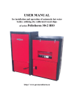
Download USER MANUAL - GreenEcoTherm
Transcript
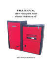
USER MANUAL of hot water pellet boiler of series “Pelletherm v2” http:// www.greenecotherm.eu Producer Address Phone Fax e-mail home page ZMM Haskovo Plc. Bulgaria, Haskovo 6300, “Saedinenie” 67 blvd. +359 800 15 145 +359 38 603070 [email protected] www.greenecotherm.eu Thank You for buying hot water pellet boiler of series „Pelletherm v2”. This manual will help You to use and maintain the unit properly. The boiler’s producer company requires the installer technicians, which will perform the installation, maintenance and service procedures of the boilers of series “Pelletherm v2” to be trained and certified by the producer. NOTE: in the following document is used the designation “Pelletherm v2”, which includes all the models of the hot water pellet boilers: “Pelletherm 30v2” and “Pelletherm 45 v2”. ATTENTION! IN INTEREST OF YOUR PERSONAL SECURITY IT IS OBLIGATORY TO READ THOROUGHLY AND CAREFULLY THIS INSTRUCTION MANUAL BEFORE PROCEEDING WITH ANY ACTIONS WITH THE BOILER – MOUNTING, CONNECTING, ETC. IN CASE THAT REQUIREMENTS, DEPICTED IN THIS MANUAL ARE NOT SATISFIED, FAILURES OF THE UNIT COULD BE EXPECTED, OR EVEN FATAL CONSEQUENCES, FOR WHICH THE PRODUCER COMPANY DOES NOT TAKE RESPONSIBILITY. Hot water pellet boiler of series “Pelletherm v2” user manual ; (document version: 29/10/2012 15:04) p. 2/49 CONTENTS page 1. Hot water pellet boiler of series “Pelletherm v2” – description, properties and advantages. ................................................................................. 5 The unit could utilize following types of fuel: ............................................... 5 The unit is equipped with:............................................................................... 6 The unit is supplied with : ............................................................................... 6 Hot water boiler of series “Pelletherm v2” technical data.................... 8 2. Table 2.1 Thermal and technical data for hot water pellet boiler of series “Pelletherm v2”, utilizing wood pellets. ............................................................ 9 Table 2.2 Dimensions and technical data for hot water pellet boiler of series “Pelletherm v2”. ............................................................................................... 10 Table 2.3 Recommended solid fuel properties – wood pellets. ...................... 11 Table 2.4 Pellets classification, considering their physical properties (based on fuel proximate analysis) – according to fuel evaluation methods, developed and applied in boiler’s producer company; ..................................................... 11 Table 2.5 ENplus - European standard for wood pellets; ............................... 12 Description of hot water pellet boiler of series “Pelletherm v2”. ....... 13 Installation process. ................................................................................ 17 3. 4. 4.1. Hot water pellet boiler connection methodology ............................... 20 4.1.1. Connecting to the chimney ....................................................... 20 4.1.2. Connecting to the heating system ............................................ 20 5. Hot water boiler installation and starting procedures. ....................... 23 5.1. Basic fuel requirements....................................................................... 23 5.2. Starting hot water pellet boiler of series “Pelletherm v2” procedure. ............................................................................................................... 24 5.2.1. Interface control board of hot water pellet boiler of series “Pelletherm v2” ................................................................................................. 25 5.2.2. Hot water boiler power supply. ............................................... 26 5.2.3. Hot water boiler very first start. .............................................. 26 5.2.4. Main parameters for boiler operation. ................................... 27 5.2.5. Adjustment process of the boiler according to the thermal load of the building/consumer. ......................................................................... 31 p. 3/49 5.2.6. module. Changing the working parameters of the process control ..................................................................................................... 34 5.2.7. Nominal operation mode of the boiler..................................... 37 5.3. Adjustment of the thermal capacity of the boiler............................. 38 5.3.1. Decreasing the thermal capacity of the boiler:....................... 38 5.3.2. Increasing the thermal capacity of the boiler: ....................... 39 5.4. Stopping the operation of hot water pellet boiler. ............................ 39 5.5. Turning OFF the boiler....................................................................... 40 Emergency boiler stop. ......................................................................... 40 5.6. Showing and teaching the end user about the maintenance and adjustment procedures. ................................................................................. 41 5.7. Safety and unexpected risks ............................................................... 41 5.8. Operation faults and their repairing ................................................. 43 5.9. Hot water boiler warranty form completion. ..................................... 46 5.10. Actions, after the unit is not in exploitation anymore...................... 46 Electrical scheme of automatic pellet boiler of series “Pelletherm v2”. ................................................................................................................... 47 WARRANTY CONDITIONS .......................................................................... 49 6. p. 4/49 1. Hot water pellet boiler of series “Pelletherm v2” – description, properties and advantages. “Pelletherm v2” is steel-plate hot water pellet boiler, which uses solid biomass fuel in shape of pellets. The boiler is designed to be connected to local hot-water heating systems, as well as heating up domestic hot water. The boiler uses wood pellets, as well as other type/shape of biomass, the resulting heat energy from thermo-chemical conversion (i.e. combustion process) is transmitted to the circulation water in its water jacket and the heat energy is transported to the heating system/consumer. The hot water pellet boiler of series “Pelletherm v2” includes: hot water boiler – 1 sp.; ash tray – 1 sp.; foot-screws for installation and leveling – 8 sp.; pair of working gloves – 1sp.; working apron – 1 sp.; instruction manual – 1 sp.; annex of the instruction manual – 1 sp; The unit could utilize following types of fuel: Wood pellets, having diameter 6 up to 14 mm, categorized in the range of: A, AB, B, BC, C, CD, E, EF (according to the methodology, developed for pellets properties estimation in boiler’s producer company); Pre-dried nuts (cherries for example); Fuel mixture – pellets and nuts (for example mixture ratio could be 50% - 50%); Pellets, produced of any other solid biomass (for example olive husk residue); Other solid biomass based pellets, but confirmation for these fuels utilization need testing and approval by boiler’s producer company laboratory; p. 5/49 The unit is equipped with: Steel plates welded heat exchanger for heating-up the circuit water; Flue gas fan; Fresh air supplying fan; Burner’s ash removal mechanism – removes the ash residuum out of the burner’s grate; Daily fuel hopper with capacity of about 100 kg; Programmable operating module, which controls the functions of the unit and is adjustable to the specific need of a heating system as well as the properties of the fuel; Ash residue container with capacity of approximately 5 kg; Manually driven semi-automatic ash cleaning system (this system cleans the ash, deposited on the internal surface of the pipes of boiler’s convective section); The unit is supplied with : Automatic fuel ignition system; Automatic burner’s ash removal system; Semi-automatic ash (deposited on the surfaces of the heat exchanger pipes) cleaning system; Automatic fuel feeding auger system; Unit’s advantages : The hot water boiler is designed to utilize solid biomass fuel, making it environmentally friendly, CO2 neutral and does not contribute to the global warming process – result of fossil fuel utilization; The specific price of the heat energy, delivered by solid biomass utilization is less dependent on the world fuel market trends and practically the heat energy price is competitive to the conventional energy sources; p. 6/49 The boiler is automatic and the thermal comfort achieved is close to that, originating from exploitation of fully automatic boilers, (for example liquid or gas fuel, as well as electric boiler), which makes is applicable in heating systems, equipped with programmable room thermostat; The unit is equipped with automatic fuel ignition system and another one for burner’s grate ash cleaning; The design of the heat exchanger is optimized and realizes three way flue gas duct, thus allowing intensive heat exchange rate and high efficiency of the boiler (above 90%) and reduced fly ash emissions to the chimney; Automatic unit operation. Hot water boiler could be connected to programmable room thermostat (weekly programmable), which guarantees maximal thermal comfort and economical fuel consumption; The unit utilizes solid biomass fuel, in shape of pellets (wood pellets), dried nuts (cherry nuts for example), which have ash contents higher that the limits, defined in following norms : ENplus (EN 14961-2:2010), ONORM M7135, DIN 51731 и DINPlus; High efficiency; Low pollutant contents in the flue gases; The unit is applicable for domestic hot water heating purposes (DHW); Automatic fuel feeding system, transported from the built-in “daily” hopper to the burner; The control operating module can operate the function of additional external fuel feeding system, which deliver fuel to the built-in fuel hopper from external one; Simplified maintenance and service procedures; Minimized running costs; p. 7/49 2. Hot water boiler of series “Pelletherm v2” technical data. Thermal and technical data for hot water pellet boiler of series “Pelletherm v2”, utilizing wood pellets are given in Table 2.1; Dimensions and technical data for hot water pellet boiler of series “Pelletherm v2” are given in Table 2.2; Recommended solid fuel properties – wood pellets, are given in Table 2.3; Pellets classification, considering their physical properties (based on fuel proximate analysis) are shown in Table 2.4; ENplus – the European standard for wood pellets is shown in Table 2.5; p. 8/49 Parameter Model of the hot water boiler Nominal thermal capacity Thermal capacity operation range Utilized solid fuel Utilized wood pellets, complying ENplus Utilized pellets, complying with boiler’s producer classification methodology Wood pellets fuel consumption rate at nominal thermal capacity Fresh air flow rate, required for effective combustion process and boiler operation Mass flow rate of the exhaust gases Averaged wood pellets consumption rate (the unit is operating in a popular heating system) Thermal efficiency at nominal capacity Air excess ratio Flue gases temperature at nominal thermal capacity Solid fuel residue Dimension Value Pelletherm Pelletherm 30v2 45v2 kW 30 45 kW 9 – 30 13 - 45 Wood pellets; Pre-dried cherry nuts; Other dried nuts;; ENplus-A1, ENplus-A2, ENplus-B A, AB, B, BC, C, CD, D, DE kg/h 6.9 10.4 kg/h 50 - 60 75 - 90 m3/h 42 - 50 63 - 75 g/s 18.6 27.9 kg/h 4.5 6.75 ℅ λ 93.4 93.2 1.4 – 1.6 ºC 110 – 120 ash The quantity depends on the ash contents in the raw fuel, as well as operating conditions 140 - 150 Table 2.1 Thermal and technical data for hot water pellet boiler of series “Pelletherm v2”, utilizing wood pellets. p. 9/49 Parameter Dimension - Value Pelletherm Pelletherm 30v2 45v2 460 575 95 120 152 100 kg wood pellets 1515 x 850 x 1618 x 850 1375 x 1380 3 MPa 0.25 Model of the hot water boiler Weight Water jacket capacity Fuel hopper capacity Overall dimension of the unit (WxDxH) Class (according to EN 303-5) Operating overpressure of the circulating water Heating system expansion vessel type Factory tested overpressure Recommended circulating water temperature Minimal recommended return water temperature Draught Supply/return flow Connections Drainage Flue gases duct Hydraulic losses of the circulating water at nominal thermal capacity Power supply Electrical capacity Electric protection kg dm³ dm³ kg mm MPa Opened or closed (up to 0.25MPa) 0.4 ºC 80 ºC 60 hPa 0.1 - 0.2 G 1½” G ½” mm 150 - hPa VA - 2.95 5.94 L1, N, PE, 50Hz; 230V 120 + 250 (at ignition process) IP20 Table 2.2 Dimensions and technical data for hot water pellet boiler of series “Pelletherm v2”. p. 10/49 Parameter Pellet’s characteristic size Recommended fuel net calorific value (low heating value) Wood pellet class Wood pellets category Ash content Moisture content Dimension mm MJ/kg kWh/kg Value 6 – 14 >17.2 >4.7 ENplus-A1, --ENplus-A2, ENplus-B A, AB, B, BC, C, CD, E, EF % See Table 2.4. and Table 2.5 % Max. 8 – 10% Table 2.3 Recommended solid fuel properties – wood pellets. Pellet’s category A AB B BC C CD D DE E EF Ad DU A 0.6% Ad 0.6% 0.6 Ad 1.0% 0.6 Ad 1.0% 1.0% Ad 2.0% 1.0% Ad 2.0% 2.0% Ad 3.0% 2.0% Ad 3.0% Ad 3.0% Ad 3.0% DU 97.0% DU 97.0% DU 97.0% DU 97.0% DU 97.0% DU 97.0% DU 97.0% DU 97.0% DU 97.0% DU 97.0% d Table 2.4 Pellets classification, considering their physical properties (based on fuel proximate analysis) – according to fuel evaluation methods, developed and applied in boiler’s producer company; where: Ad – ash contents, dry basis, [%]; DU – mechanical durability, [%]; p. 11/49 The European wood pellets standard EN 14961-2:2010 defines wood pellets certificate ENplus for pellets, utilized in boilers and appliances for domestic heating systems. The certificate EN-B is applied for pellets, utilized in industrial boilers. In principal the ENplus standard defines two quality classes: А1 и А2. The class А1 is highly restricted, considering the ash content. The class А2 the limit of the ash content of the wood pellets is higher – up to 1.5%. For industrial boilers the certificate EN-B is applicable, which defines fewer restrictions on the pellets quality. Parameter Diameter Length Bulk density Low calorific value Moisture content Dust Mechanical durability Ash content Ash melting point temperature Cl S N Cu Cr As Cd Hg Pb Ni Zn Dimension mm mm kg/m³ MJ/kg % % % % 2) °C % 2) % 2) % 2) mg/kg 2) mg/kg 2) mg/kg 2) mg/kg 2) mg/kg 2) mg/kg 2) mg/kg 2) mg/kg 2) ENplus-A1 6 (± 1) 3,15 ≤ L ≤ 40 1) ≥ 600 ≥ 16.5 ≤ 10 ≤ 13) ≥ 97.5 4) ≤ 0,7 ≥ 1200 ≤ 0.02 ≤ 0.05 ≤ 0.3 ≤ 10 ≤ 10 ≤1 ≤ 0.5 ≤ 0.1 ≤ 10 ≤ 10 ≤ 100 ENplus-A2 6 (± 1) 3,15 ≤ L ≤ 40 1) ≥ 600 ≥ 16.5 ≤ 10 ≤ 1 3) ≥ 97.5 4) ≤ 1.5 ≥ 1100 ≤ 0.03 ≤ 0.05 ≤ 0.5 ≤ 10 ≤ 10 ≤1 ≤ 0.5 ≤ 0.1 ≤ 10 ≤ 10 ≤ 100 1) not more that 1% of the wood pellets should be with length of 40 mm, the maximal pellet length is 45 mm ; 2) determined on dry mass; 3) the particles are <3.15 mm, fine particles, before fuel delivery; 4) in case the test measurements are performed with Lignotester, than the limit value is ≥ 97.7% m.w.; Table 2.5 ENplus - European standard for wood pellets; p. 12/49 3. Description of hot water pellet boiler of series “Pelletherm v2”. The heat exchanger of the boiler complies with the acting requirements for such kind of units, defined in operating norm : EN 303-5/2000 – „Heating boilers for solid fuels, hand and automatically fired, nominal heat output up to 300 kW. Terminology, requirements, testing and marking”. The unit consists of: Main part of the unit is heat exchanger. In the combustion chamber of this exchanger is mounted specialized grate burner, designed for horizontal fuel feeding; The heat exchanger is welded construction of carbon steel plates and steel pipes. The lower part of the exchanger is designed as combustion chamber. The burner is mounted in this chamber and conditions efficient combustion process; Stainless steel burner, mounted in the combustion chamber of the heat exchanger; Ash container, positioned in the lower part of the combustion chamber, below the burner; Fuel hopper is mounted aside of the boiler’s heat exchanger. Beneath the hopper is mounted a fuel-auger separator (which also acts as fuel proportioner), followed by horizontal transport auger. The fuel proportioner prevent the so called “back fire” process, i.e. ignition of the fuel in the hopper by the hot flue gases in the auger duct in case of abnormal situations; Fresh air fan is mounted on the air duct of the burner. The fan is equipped with position adjustable flap in order to set the air flow rate. Additionally the air duct is equipped with flaps for individual adjustment of the primary and secondary air flow rate. These flaps are factory set and in principal need no adjustment; Inflow and outflow connections (to/from the heating system) of the supply and return circulating water are internal threads, positioned in the rear side of the heat exchanger; Draining connection is internal thread, diameter G½” and is positioned on the lower part of rear side of the heat exchanger. An appropriate drainage valve should be connected; p. 13/49 Flue gases exit duct is positioned in the upper rear side of the heat exchanger (after the flue gases fan, concerning the flue gases track), utilized for forced flue gases extraction; Boiler’s heat exchanger is covered with decorative covers, isolated with mineral wool plates, ensuring low heat losses to the ambient environment; Outer decorative covers are carbon steel plates color painted details; Figure 3.1 External view of hot water pellet boiler of series “Pelletherm v2”; The unit is designed and assembled in two main modules – the heat exchanger (the left one) and the fuel hopper module (the right one). These modules are easily detachable and could be assembled onsite if necessary; The producer reserves the right to make changes of the design of the hot water boiler of series “Pelletherm v2” without obligations to inform the clients for that process. p. 14/49 Heat exchanger of the boiler Fuel hopper Control board Fuel proportioner Fuel transport auger Burner’s ash cleaning system Figure 3.2 Partly sectioned view of hot water pellet boiler of series “Pelletherm v2” – front view; Flue gases exit duct External fuel delivery orifice Figure 3.3 External view of hot water pellet boiler of series “Pelletherm v2” – top view; p. 15/49 Tertiary pass of flue gasses Secondary pass of flue gasses Primary pass of flue gasses Specialized pellet burner, equipped with ash cleaning mechanism Ash container Figure 3.4 Cross section view of hot water pellet boiler of series “Pelletherm 30 v2”. The flue gasses duct and streamlines are visualized as well; Tertiary pass of flue gasses Secondary pass of flue gasses Primary pass of flue gasses Specialized pellet burner, equipped with ash cleaning mechanism Ash container Figure 3.5 Cross section view of hot water pellet boiler of series “Pelletherm 45v2”. The flue gasses duct and streamlines are visualized as well; p. 16/49 4. Installation process. Norms and recommendations. Basic requirements for installation of hot water pellet boiler of series “Pelletherm v2”: The room, dedicated to mount the boiler, should be supplied with fresh air supply duct, necessary for optimal combustion process as well as room ventilation; Installation of the unit in inhabitable premises, including dwelling corridors, is not allowed; The hot water boiler should be connected to the heating system by authorized personal only; Installation and service procedures of solid fuel hot water boilers should be performed by authorized qualified and certified personal ONLY; The hot water pellet boiler of series “Pelletherm v2” should be connected to heating system, supplied with OPENED or CLOSED expansion vessel. In case the heating system is equipped with closed expansion vessel, then the system should be equipped with over-pressure safety valve, which opens at pressure exceeding the operating one of the hot water boiler (0.25 MPa) and this overpressure safety valve should be certified according to PED 97/23; Both the entire heating system and the boiler should be totally filled with circulating fluid (water) and air-free before operating the boiler; Maintenance procedures of the boiler should be performed by trained adult persons, which have read the user manual of the unit; Installation procedure of the boiler requires engineering project for the heating system, prepared according to the acting local norms and recommendations as follows: To the heating system - EN 303-5/2000 - „Heating boilers. Part 5 : Heating boilers for solid fuels, hand and automatically fired, nominal heat output of up to 300 kW. Terminology, requirements, testing and marking”; To the chimney; Fire prevention requirements; To the power circuit - EN 60335-1/1997- “Household and similar electrical appliances – safety, Part 1 – General requirements”; p. 17/49 Appliance positioning in order to achieve comfortable maintenance. o Minimal distance of 1000mm in front of the unit and any wall should be provided; o Minimal distance of 400mm from the rear wall of the unit and any wall should be provided; o Minimal distance of 500mm from the right hand side of the unit and any wall should be provided, in order to guarantee easy access to the fuel transporting auger; o Minimal distance of 300mm from the left hand side of the unit and any wall should be provided, in order to guarantee easy access at servicing of the flue gas fan of the unit; o Minimal distance of 600mm above of the unit and any ceiling(wall) should be provided, in order to guarantee easy access to the fuel’s hopper, as well as enough room for cleaning purposes of the heat exchanger body as well as fuel hopper charging; Figure 4.1 Positioning of hot water pellet boiler of series “ Pelletherm v2” – the minimal distances between the unit and any walls/obstacles of the boiler’s room are shown; The hot water boiler should be positioned in the boiler’s room according to the requirements for attaching electrical appliances to the power circuit – the unit should be positioned in a way, that will provide easy access to the power supply plug (230V/50Hz); ATTENTION: the installation process of the boiler is finalized by performing so called “hot tests” procedure of the heating installation and the warranty card is filled with the required information. p. 18/49 The recommended principal hydraulic scheme for connecting the hot water pellet boiler of series “Pelletherm v2” to the heating system is snow on the following figure. Cold tap water To heating system Domestic hot water From heating system Tap water drainage Figure 4.2. Recommender principal hydraulic scheme for connecting the hot water pellet boiler of series “Pelletherm v2” to the heating system, equipped with mixing valve and heat accumulator; Index 1 2 3 4 5 6 7 8 9 10 11 Designation Hot water boiler of series “Pelletherm v2” Safety valve Hot water boiler Return valve Circulating pump 1 Control valve Expansion vessel Control valve Three way mixing valve Circulating pump 2 Control valve Index 12 13 14 15 16 17 18 22 23 24 Designation Water filter Thermovalve TV Return valve Contact thermostat Heat accumulator Automatic circulating water charger Drainage valve Automatic air separator Safety valve Return valve Table 4.1. Designation of the elements, indexed on figure 4.2 p. 19/49 NOTE : According to EN 303-5 the heat accumulator is obligatory module of a heating system, equipped with solid fuel hot water boiler. The dimensioning of the heat accumulator tank is described in the above mentioned standard. The boiler producer could assist in appropriate designing of that module as well. 4.1. Hot water pellet boiler connection methodology 4.1.1. Connecting to the chimney After the boiler has been positioned and leveled (utilizing the leveling screws, installed in the lower corners of the heat exchanger as well as the fuel hopper module), the unit should be connected to an appropriately sized and designed chimney. 4.1.2. Connecting to the heating system After the flue gas duct of the boiler is connected to a chimney, the boiler should be connected to the heating system – utilize appropriately sized fitting, according to the preliminary prepared project. p. 20/49 Figure 4.3. Back side view of heat exchanger connections of hot water pellet boiler “Pelletherm 30 v2”; p. 21/49 Figure 4.4. Back side view of heat exchanger connections of hot water pellet boiler “Pelletherm 45 v2”; p. 22/49 5. Hot water boiler installation and starting procedures. ATTENTION : The unit should be installed, adjusted and verified ONLY by trained and authorized staff. 5.1. Basic fuel requirements. The fuel, pellet shaped, should be dry. The unit producer recommends that the fuel should be stored in dry and well ventilated rooms; It is strongly forbidden to store the fuel in close region of the boiler, the minimal safety distance between the fuel and the appliance is 400 mm; The unit producer recommends an optimal distance between the boiler and the fuel container to be at least 1000mm. It is recommended to store the fuel in room, next to that, where the boiler is installed; At the installation procedure of the unit, as well as the fuel storage one, fire prevention recommendation should be considered. It is also recommended to install a fire-extinguisher in a safe and easy accessible place; In principle heating systems, which are hydraulically opened to the atmosphere allow direct contact between the circulating fluid (in most cases it is water) and the air. During the heating season the water content in the expansion vessel absorbs oxygen from the atmosphere though the free surface. The increased oxygen content in the water threatens the metal of the unit, as well the pipes. Through the free surface of the expansion vessel water evaporation is observed as well. Considering these, appropriate water should be added through the expansion vessel – it must cover the requirements of norm BDS 15207-81. During the heating season regular checking of circulating water level in the expansion vessel should be performed by the end user. The water content in the circulating system should be kept constant. If additional water is required, then precautions should be taken, not to add air in the heating system as well. The water, utilized for filling purposes of the heating system should be decontaminated and air-free, and is not dedicated for any other purposes, but as a circulating fluid only. Any heating system drainage is inadmissible, except when repairing modules/sections of the system. Practical experience shows that water level checkup should be performed regularly in a period of 14 days in order to sustain quasi-constant water content. In case that additional water is required, the filling process should be performed carefully, when the hot water boiler is cooled to the ambient p. 23/49 temperature. This precautions are induced due to prevent rising of thermal stress of the steel boiler’s body and its damage (leakage). In case that the boiler as well as the heating installation will not be in exploitation for a long period, then in order to prevent local water freezing and damages, it is advisable to perform total drainage of the circulating water. Please take into account that the presence of liquid in the heating system, as well in the boiler will prevent oxidation process of the metal surfaces, corrosion and system failures. 5.2. Starting hot water pellet boiler of series “Pelletherm v2” procedure. Basic requirements: Any maintenance procedures should be performed in accordance with the described in this manual; Any intervention in the working process of the unit, which could lead to unit’s failure and/or dangerous and health threatening situations, are strongly prohibited; The unit should be checked by the maintenance staff or any trained personal regularly; The end-user should not perform any interventions, repairs, etc. of the unit. In case that warning and failures arise, check the failures table (applied at the end of this manual) and call the service support if the case is not described there; Any adjustments of thermal capacity higher than the nominal thermal load of the units are not allowed; The ash, deposited in the combustion chamber of the boiler, should be collected in fireproof containers and cooled down to ambient temperature. The cooled ash should be disposed in appropriate waste containers. Please take into account that the mineral ash, result of wood biomass pellets could be considered as soil fertilizer and dispersed for agricultural purposes for example; The door of the fuel hopper section of the boiler is equipped with a safety switch and in case the door is opened, then the motor of the fuel transport auger will be powered off for safety reasons – this door should be kept closed; p. 24/49 5.2.1. Interface control board of hot water pellet boiler of series “Pelletherm v2” Process control module Alarm indicator (emergency overheating) Alarm indicator – (process malfunction) Thermo-manometer Operating thermostat Emergency thermostat “START” switch Main “POWER” supply switch Figure 5.1. Interface control board, equipped with control and operating devices of hot water pellet boiler of series “Pelletherm v2”. Interface control board devices description: Main “POWER” switch – switches ON and OFF the main power supply of the boiler; Operating thermostat – assigns the set-point of circulating water in the boiler. The boiler will run until this set-point is reached and will supply heat energy to the heating system; Emergency thermostat – protects the boiler from exceeding emergency temperature level and boiler overheating. This thermostat is factory preset to switch off the unit at water temperature in the boiler above 95oC; p. 25/49 Thermo-manometer – indicates the operating temperature of the circulating water in the heat exchanger jacket of the boiler, well as water overpressure; “START” switch – sends “START/STOP” signal to the process control module, which controls the operation of the boiler; Process control module – a programmable unit, that controls the functions of unit according to predefined program (firmware); Alarm indicator -process malfunction – indicates any abnormal state of the boiler, for details check the information, written on the process control module’s display; Alarm indicator – emergency overheating – indicates emergency overheating state of the boiler, due to activation of the emergency thermostat of the boiler. In case of activation, cool down the unit and check and repair the reason for the emergency situation, finally reset the emergency thermostat; 5.2.2. Hot water boiler power supply. The boiler should be connected to the chimney according to the installation’s project. This duct should be sealed and verified that there is no flue gases leakage; The boiler should be connected to the heating system, the system, as well as the water jacket of the heat exchanger should be filled with circulating liquid, free of air, the control modules (valves, pumps, motor-valves, etc.) should be checked for functionality as well; The unit should be connected to the main power supply, according to the safety rules and appropriate norms; The hopper should be filled with pellets, in order to transport fuel material by the pellet feeding auger to the burner. It’s recommended to set the pellet hoper lid closed, in order to preserve uncontrolled air penetration to the combustion chamber through this tract; 5.2.3. Hot water boiler very first start. The unit is switched on by the main “POWER” supply switch, placed on the control board. The unit gets activation signal by switching ON the “START” and goes into automatic operating mode – it goes through ignition mode if needed. If the “START” switch is OFF then the boiler goes into stand-by mode and waits until new command arise. In case of power supply break-down the boiler will go into the same state of the unit before the interruption. p. 26/49 ATTENTION : During the operation of the boiler when the door of the combustion chamber is opened, it is possible to observe smoke leakage through the transport auger tract as well as the pellet hopper. Because of these reasons the opening of that door is not recommended. The same processes could be observed at the transition periods – during spring and autumn seasons, when the chimney’s draught is reduced due to high ambient temperature. COMMENTS: At the period of fuel ignition an electrical heater is activated. The heater will be deactivated when the flue gas temperature reaches certain level, sensed by flue gas thermostat, mounted on the exhaust duct of the boiler; During the very first starting period of the unit it takes time to fill the auger volume with fuel. According to the settings of the unit the first ignition may fail. If this is the case, please restart the unit (by switching OFF and ON by the main POWER switch) and check the ignition process again; The boiler is operating, controlled by predefined algorithm, loaded in the process control module. The program itself is protected against unauthorized intrusion by a password. The user can change some unlocked and unprotected parameters. The meaning of any available parameter should be clear before any intervention and changes, otherwise the operating results are hardly predictable and malfunction could be caused; 5.2.4. Main parameters for boiler operation. The following table contains parameters, which define boiler’s heat capacity. Parameter Т4 Т6 Description Pellet’s feeding time – during this period pellets are fed to the burner; Pellet’s not feeding time (fuel is not transported to the burner) Recommended value Pelletherm Pelletherm 30v2 45v2 20 17.0 20 Dimension seconds seconds Table 5.1 Main parameters description, which define heat capacity of the unit. ATTENTION : The producer guarantees effective and reliable operation of the boiler ONLY when its running conditions are in its corresponding operating p. 27/49 range. That’s why if any parameter is changed, it’s value should be checked and verified to lie in the appropriate limits. Special care should be taken to fulfill the following requirements: the ratio of the described periods T4 and T6 - (Т4/Т6) should be in the following range : For „Pelletherm 30v2”: 6 T 4 20 0.30 1.00 , where 20 T 6 20 6.0 0.30 20 defines the lower thermal capacity of the boiler, corresponding to about 9kW, and the ratio 20 1.00 defines the nominal thermal capacity of the 20 unit; For „Pelletherm 45v2”: 5.1 T 4 17 0.26 0.85 , where 20 T 6 20 5.1 0.26 20 defines the lower thermal capacity of the boiler, corresponding to about 13.5kW, and the ratio defines the nominal thermal capacity of the unit; NOTES: The choice of these parameters could be preceded as well as followed by other parameters, which are not described in the table above. These parameters are dedicated to be varied by authorized trained service personal and their variation by the end user is not recommended; The producer reserves the right to change the specification and/or the design/adjustment of the unit without prior notice; The table above contains factory default values for the parameters of the settings of the process control module, which lead to optimal unit adjustment; The described parameters : T4 and T6 are most frequently changed – they define the thermal capacity of the unit and its operating regime; The following table contains main parameters, which are utilized to control the functionality of the boiler. Any changes of the parameter’s values should be done in case that the meaning and the influence of a changed parameter is preliminary known. In case that a parameter’s value should be changed, it is recommended to be done by trained authorized technician only. p. 28/49 Parameter Т1 Т2 Т4* Т5 Т6* Т7 Т9 ТB ТС C Description Period of time for conducting initial doze of fuel to the burner Maximal period of time until stable combustion process is achieved Pellet’s feeding time – during this period pellets are fed to the burner – determines the heat capacity of the unit; Period of time for fuel combustion after STOP signal has been set Pellet’s not feeding time (fuel is not transported to the burner) - determines the heat capacity of the unit; Period of time for initial fuel doze combustion Period of time between two cleaning procedures. ATTENTION : change the value of the period only – tВ Period of time, which generates false hysteresis of the level of the fuel in the pellet hopper Period of time for fuel combustion before burner’s ash cleaning mechanism actuation Ignition attempts counter (C1) (EXPLANATION : at С=4 the boiler makes 3 (three) ignition attempts); Recommended value Dimension Pelletherm Pelletherm 30 v2 45 v2 300 seconds 900 seconds 020 17.0 seconds 30м:00 s minutes: seconds 020 seconds 60 seconds tA=00.02 tВ = 04.00 h:m hours: minutes 60 seconds 400 seconds 4 count Table 5.2 Description of the control parameters, which define nominal operating mode of the hot water boiler of series “Pelletherm v2”. p. 29/49 NOTES: In principal the fuel’s ash content does not change its low calorific value. However, the combustion process is greatly influenced by the presence of mineral mass, i.e. ash, but requires specially designed burner in order to achieve efficient and reliable operation. The above mentioned requires appropriate testing and verification of the fuel’s applicability as energy source for the hot water pellet boiler of series “Pelletherm v2” before making nominal exploitation of the unit. Consult the requirement for fuel of the boiler or request the appliance producer’s assistance; The table above contains factory default values for the parameters of the settings of the process control module, which lead to optimal unit adjustment and efficient boiler’s operation; The described parameters : T4 and T6 are most frequently changed – they define the thermal capacity of the unit and its operating regime; The adjustment of appropriate thermal capacity of the units could be realized through field fuel mass flow rate measurement. The fuel is collected at the exit of the burner by switching the unit to normal operation mode for a measured period of time and thus the flow rate is calculated. The appropriate adjustment shall be done through fuel mass flow rate determination, considering the fuel net heating value as well as thermal efficiency of the boiler. Here an example of thermal capacity determination is given : o Average fuel mass flow rate is determined (per hour)- mpellets=6.8 kg/h. The instant mass flow rate is calculated as follows : the average fuel mass flow rate value is divided by 3600 ( 1 hour = 3600 seconds) and the result is m’pellets = 0.00188 kg/s; o The net calorific value of the pellets is considered (given by the fuel producer, other source, etc.) – Hpellets = 17.2 MJ/kg = 17200 kJ/kg; The practice shows that in some cases it is more convenient to utilize another dimension of the calorific value – kWh. The wood pellets have low calorific value of H’pellets = 4.77 kWh/kg (which is equal to 17.2 MJ/kg); o The thermal efficiency is considered (stated by the producer) at nominal thermal capacity : - ηboiler=93%=0.93; o The thermal capacity of the boiler is calculated as follows Pboiler boiler * H pellets * m' pellets 0.93 *17200 * 0.00188 30.2 kW. In case that the calorific value of the fuel is known in dimension kWh/kg, then the calculation is as follows Pboiler boiler * H ' pellets *m pellets 0.93 * 4.77 * 6.8 30.2 kW; p. 30/49 o Any other thermal capacity of the boiler is calculated, following the described procedure above – for example if the fuel has different calorific value or the required thermal capacity is lower, than the nominal one; The producer reserves the right to make changes of the setting of the process control module without obligations to inform the clients for that process; 5.2.5. Adjustment process of the boiler according to the thermal load of the building/consumer. It is recommended to make appropriate adjustments of the process control module parameters in order to obtain high efficiency and reliable performance of the boiler, considering the thermal load that should be supplied by the boiler. The required heat capacity for heating purposes of a common house could be assumed to be a linear function of the temperature gradient ΔТ (the difference between the mean value of temperature level in the heated rooms and the ambient temperature level). Thus the optimal operation process of the boiler requires regular adjustment of the “heat capacity” parameters of the unit. EXPLANATION : the data, shown in the following table are calculated on the assumption that the mean temperature level in the heat supplied rooms of the building is Тroom =20[oC]. If any other value is the case, than refer the temperature gradient instead; Тambient air Ratio T4/T6 Т4* Heat capacity Т6 C - seconds kW seconds -15 35 1.00 20.0 30.0 -10 30 0.80 16.0 24.0 -5 25 0.60 12.0 18.0 0 20 0.30 6.0 9.0 o C ΔТ o 20 Table 5.3. Appropriate adjustments of “heat capacity” parameters Т4 and Т6 according to the thermal load of the boiler “Pelletherm 30 v2”; where : Тroom – mean value of the temperature in the heated rooms, [oC]; Тambient air – mean value of the ambient temperature, [oC]; p. 31/49 ΔТ= Тroom – Тambient air - temperature gradient, [oC]; Тambient air Ratio T4/T6 Т4* Thermal capacity Т6 C - seconds kW seconds -15 35 0.85 17.0 45.0 -10 30 0.68 13.6 36.0 -5 25 0.51 10.2 27.0 0 20 0.26 5.1 13.5 o C ΔТ o 20 Table 5.4. Appropriate adjustments of “heat capacity” parameters Т4 and Т6 according to the thermal load of the boiler “Pelletherm 45 v2”; * The value of parameter Т4 is determined according to the assumption that value of parameter T6 is conserved constant, i.e. Т6=20 seconds; ATTENTION : In case that the boiler is working for heating purposes of domestic hot water ONLY, than the heat capacity of the unit should be considered the T4/T6 ratio limits as follows : for “Pelletherm 30v2” : T4 0.30 ; T6 for “Pelletherm 45v2” : T4 0.26 ; T6 COMMENT : The above defined values of the “heat capacity” parameters are given for certain fuel – wood pellets with diameter d=8mm. In case that the fuel type or its characteristic size is different than 8mm diameter wood pellets, than these values should be considered as basis for appropriate adjustment of the boiler. However, one should check the values of other operating parameters – for example T1 or T9. p. 32/49 Pellet’s feeding time, [seconds] Ratio T4/T6 1.0900 21.000 0.9900 19.000 0.8900 17.000 0.7900 15.000 0.6900 0.5900 13.000 0.4900 11.000 0.3900 9.000 0.2900 7.000 0.1900 5.000 0.0900 9.00 18.00 24.00 30.00 9.00 18.00 24.00 30.00 Heat capacity of the boiler, [kW] Figure 5.2. Graphics of the T4 parameter and power ratio (pellet’s feeding time – Т4 and ratio T4/T6) values, according to the heat capacity of the hot water boiler “Pelletherm 30 v2”; Pellet’s feeding time, [seconds] Ratio T4/T6 0.8900 19.000 0.7900 17.000 0.6900 15.000 0.5900 13.000 0.4900 11.000 0.3900 9.000 0.2900 7.000 0.1900 0.0900 5.000 13.50 27.00 36.00 45.00 13.50 27.00 36.00 45.00 Heat capacity of the boiler, [kW] Figure 5.3. Graphics of the T4 parameter and power ratio (pellet’s feeding time – Т4 and ratio T4/T6) values, according to the heat capacity of the hot water boiler “Pelletherm 45 v2”; p. 33/49 5.2.6. Changing the working parameters of the process control module. Algorithm for changing the value of working parameters of the process control module of the boiler: The following text describes algorithm for changing the values of any parameter of the process control unit (in case it is necessary !). It’s recommended to change these parameters only when it is necessary. The physical meaning of any parameter should be clarified, as well as the influence of a parameter on the performance of the boiler. The displayed parameters are allowed to be changed: 1. Press the green button (●), marked Menu/OK on the interface panel of the process control unit. A menu list will be displayed; 2. Press buttons arrow DOWN (▼) or UP (▲) and choose the item “PARAMETER”; 3. Press button arrow UP (▲) until reaching the desired parameter – Т4 or Т6; NOTE: Do not try to change any other parameter, unless the meaning and the influence on the performance of the unit is now known a priory; 4. Press button arrow RIGHT (►) and choose the field of the parameter value; 5. Press button arrow DOWN (▼) or UP (▲) and change the value of the parameter. Note: Holding the buttons pressed arrow DOWN(▼) or UP (▲) after certain period will increase the increment of the change of the parameter’s value; 6. After the desired value is defined, press the green button Menu/OK; 7. The display of the process control module will show a question “CONFIRM CHANGES?”. Press buttons - arrow DOWN (▼) or UP (▲) until selecting the desired answer “Yes” or “Not”. Choose the answer “Yes” by pressing the green button Menu/OK, in order to confirm the change, or answer “Not” in order to reject the change of the value of operating parameter. IMPORTANT! : If the user is not confident in the necessity of the change of the value of any parameter, or the value of a parameter is changed accidentally, then it’s recommended to choose the answer “Not”. p. 34/49 8. Press the green button Menu/OK once more time and the process control module will exit the “PARAMETER” mode and will display the nominal operation process of the boiler control. NOTE: If any accidental change of a parameter has been made at the exit of this process a summary question will be displayed “CONFIRM CHANGES?” – choose the answer “NO” and any changes will be canceled. 9. Following the algorithm described above, one can change any available parameter of the process control module and can vary the setting and the performance of the boiler. NOTES: During the operating process of the boiler it is possible to arise an alarm situation (for example unsuccessful ignition process, fuel supply interruption, etc.). A short description of the alarm status is written on the display of the process control module. After removing the cause of the alarm situation, reset the operation module. The reset process of the unit is performed by switching OFF the main power supply switch and turning it back into ON position; At nominal operation process a manual ash residue removing process in the burner could be invoked by pressing the button arrow LEFT (◄). This option is dedicated for testing the performance of the cleaning module ONLY and should NOT be activated unless testing the cleaning mechanism is required. The automatic cleaning procedure is performed regularly in a predefined period of time (parameter Т9 – time period for automatic cleaning procedure); The user should choose the menu item “PARAMETER”. This submenu does not require password entry. However, the access to the service submenu items are password protected and are eligible by service technicians only; OK SHIFT Figure 5.4. Front view of the operation module of the control board of the pellet boiler p. 35/49 For example, if the user tried to get into other submenu, like “MONITORING”, then the controller will expect password entry, as described on the following figure: PASSWORD CLEAR 0/5 0000 5 = maximal number of trials for password entry SHIFT + OK = EXIT Figure 5.5. Example display, which shows the status of the submenu entry protection; The way to exit such a menu is displayed – press simultaneously the buttons “SHIFT” and “OK”. The way to exit from the displayed submenu is to press the left arrow button (◄). EXPLANATION : in case that the above described procedure is not followed, accidently the user could make up to 5 trials for password entry. After the user has made the above mentioned number of password entry trials, the display will state as depicted on the following figure. PASSWORD CLEAR ERROR 5/5 >>> 30 MINUTES Figure 5.6. Information, shows on the control module’s display at reaching the password entry trials limit; The above shown information indicates that password entry limit has been reached. The user should wait a period of 30 minutes at switched ON the power supply of the hot water boiler, until this protection times is reset. After passing the reset period (30 minutes) one should press the “SHIFT” and the “OK” simultaneously, the press the left arrow button (◄) button (follow the procedure described above). After passing the 30 minutes protection period, the control module protective timer set to 0 and one operate with the module. EXPLANATION : The user can operate within the submenu “PRAMETER” ONLY. p. 36/49 5.2.7. Nominal operation mode of the boiler. After successful ignition of the fuel and when the operating temperature of circulating water is stable it could be assumed that the hot water heating boiler is in nominal thermal load. This mode should be utilized in order to make adjustments of the operating parameters of the unit. The parameters, described in Table 5.1 (and if necessary use the parameters, described in Table 5.2) will define the thermal load of the boiler. After setting the values of operating parameters of the units, please check the position of the air flow rate adjustment flap of the air fan. The air flow rate is crucial for optimal operation and high efficiency combustion process, organized in the combustion chamber of the boiler. The nominal thermal capacity of the units should be utilized in order to perform the so called “hot test” – check the entire heating system according to the acting norms for an operating heating system (for example check for any circulating water leakages). NOTES : During the nominal thermal load of the boiler regular cleaning process is activated and the ash residue remained on the grate of the burner is removed away and is deposited in the ash container, positioned on the bottom of the combustion chamber. It should be noted that before the ash removal process, the fuel delivery to the burner is paused, while the air fan is working, thus ensuring conditions for utilization of the char, remained on the grate of the burner. A decrease of the thermal capacity of the boiler could be noticed however. Comment : the period of ash removal of the grate plate of the burner is defined by the value of parameter T9, which is described in Table 5.2. During the automatic ash cleaning interval a temporal decrease of the thermal capacity of the boiler is observed; If a circulating pump is installed in order to transport the heat energy of the boiler to the consumers, it is recommended to control the inflow temperature to the boiler to be above 60oC. In case of low inflow temperature level, condensation of water vapor could be observed on the internal heat exchanging surfaces (please consider that water vapor is one of the final products of the combustion process and always persist in the flue gases of the boiler); It is not recommended to operate the hot water boiler at thermal capacity lower than the minimal thermal load, as such regimes are not optimal and thus have low efficiency of the unit; p. 37/49 In case that continuous operation in low thermal load regimes are required, then it is recommended to connect heat accumulator to the heating system, which will ensure high efficiency, economical and reliable operation of the boiler itself, and the entire heating system in general; During the very first time of operation the boiler it is possible to observe water vapor condensation on the heat exchanging surfaces of the unit. Practically this is one-time process and will not affect the performance of the unit, neither any problems will arise as well; ATTENTION : The air flow rate is crucial for optimal operation of the combustion process, organized in the burner and the boiler overall operation effectiveness – when the air flow rate is less than the optimal one, then this insufficiency will result in incomplete combustion of the fuel, as the supplied oxygen is less than required. When the air flow rate is higher than optimal the result will be unsatisfying as well, because the excessive air will lead to low temperatures in volume for controlled combustion and will result in incomplete combustion of the fuel’s volatile gases, released by the combustion process. That’s why it is recommended to use specialized device – gas-analyzer in order to adjust the operating parameters of the control module and to optimize the boiler’s performance, thus achieving high efficiency and economical operation of the unit. 5.3. Adjustment of the thermal capacity of the boiler. The adjustment of the thermal capacity of the boiler is performed by simultaneous adjustment of the fuel flow rate and the air flow rate, supplied by a fan to the burner. The adjustment of the fuel flow rate is controlled by so called “thermal capacity” parameters (Т4 – pellet’s feeding time at nominal thermal capacity and Т6 – pellet’s combustion period, i.e. period of time, when fuel is not fed to the burner), which will determine the thermal capacity of the boiler. ATTENTION: In case of change of the fuel type (for example changing the pellets category) it should be followed by adjustment of the thermal capacity parameters and the operating mode of the boiler. 5.3.1. Decreasing the thermal capacity of the boiler: It is realized by decreasing the value of parameter Т4, which will result in decreasing the fuel flow rate (fuel consumption). The same result (decreasing the thermal capacity) is achieved by increasing the value of parameter Т6. The air flow rate should be decreased proportionally; p. 38/49 5.3.2. Increasing the thermal capacity of the boiler: It is realized by increasing the value of parameter Т4, which will result in increasing the fuel flow rate (fuel consumption). The same result (increasing the thermal capacity) is achieved by decreasing the value of parameter Т6. The air flow rate should be increased proportionally; Comment : In case of changing the thermal capacity of the boiler it is recommended to adjust the air flow rate as well, by adjusting the position of plate, controlling the air flow rate. Decreasing the air flow rate is performed by closing the flap, mounted at the entrance of the air fan, respectively – the increase of the air flow rate is realized by opening that flap; ATTENTION: Adjustment of the “thermal capacity” parameters should be performed by trained personal/end user, in order to achieve high efficient combustion process and optimal utilization of the fuel energy. It is recommended to adjust the boiler by authorized personal using gasanalyzer; In case of change of “heat capacity” parameters (T4 and Т6), it should be determined the ratio T4/T6 in order to verify that this ratio is in the range of the limits, described in the tables above, considering the boiler’s model. In case that the ratio T4/T6 exceeds the operating interval, one of the parameters (T4 or T6) should be changed in order to comply the requirements and the ratio is in the operating range. 5.4. Stopping the operation of hot water pellet boiler. Stopping the operation of the boiler should be performed by turning OFF the “START” switch, mounted on the interface panel of the unit. Respectively, the starting process will be invoked by turning “START” switch in ON position. In case that the boiler will not operate for a relatively short period of time, than it is recommended to clean the ash deposited on the easy accessed heating surfaces of the heat exchanger. ATTENTION : In case that the boiler will not operate for a long period of time, then the heat exchanger should be thoroughly cleaned from the deposited ash. The deposited on the metal surfaces ash acts corrosively on the carbon steel surfaces, which will lead to a decrease of the lifetime of the boiler’s main modules – heat exchanger, as well as the burner. It is obligatory to perform service procedures and preventive observations of the unit by trained service personal only as well as thorough cleaning at the end of the heating season. p. 39/49 Completing these requirements will ensure long exploitation time of the boiler and its high efficiency and reliability. 5.5. Turning OFF the boiler. ATTENTION : The shutdown of the equipment is done by returning the switch "START" in position - "OFF". This is the recommended way of shutdown, as is done etc. "controlled shutdown", during which the relevant fans work and the emergency signals by the boiler’s controller are monitored. After cooling, the boiler must be switched off using the switch "POWER", located on the control panel of the equipment. Is it also recommended that the equipment to be cleaned of the deposited ash. It is forbidden to stop the boiler through the "POWER" switch at work! Emergency boiler stop. In operating process of the boiler emergency situations could arise and the boiler will go into alarm/failure mode. Some situations are detected by the process control module and it will go into automatic preventive regimes in order to protect the boiler and the heating system. These regimes are operated by appropriate automatic preventive measures as well as the control module display shows a short informative text, describing the cause of the alarm state and the “ALARM” lamp is indicating the state of the boiler. Please refer the informative text on the control module’s display before taking any actions. After the cause of the alarm situation is clarified, take adequate actions for bringing back the boiler into normal operating conditions and restart the boiler by switching it OFF and back into ON state by turning the main “POWER” switch. ATTENTION : in case of emergency situation – boiler overheating, the emergency thermostat is activated, appropriate text is displayed on the control module’s display as well as indicator lamp is lit. In this case the boiler should be cooled down and the reason for such excessive process should be investigated and preventive measures should be performed. The emergency thermostat should be manually reset by unscrewing its preventive cap and its stem should be pressed until the thermostat switches back on (a “click” sound is heard in this process), screw the cap back. After the boiler is checked and the cause for overheating is determined and repaired, restart the control operation module by turning OFF the main “POWER” switch and then back ON in order to operate the boiler in normal operation mode. p. 40/49 5.6. Showing and teaching the end user about the maintenance and adjustment procedures. It is necessary to show and teach the end user the maintenance procedures for operating the boiler efficiently and keep its reliability in high degree order. Also the installer should demonstrate and teach the end user how to change the operating parameters of the control module of the boiler in order to operate the unit in different modes and heat capacities, according to the local heat consumption: Fuel hopper charging – the fuel is poured out in the hopper of the boiler and the hopper’s cap should be closed in order to prevent uncontrolled air penetration to the burner through this section; Ash cleaning procedure – it is recommended to clean periodically the ash residue (at least once per day) the convective heat exchanger part of the unit by manually swinging the cleaning lever for semiautomatic ash cleaning process. Covering this requirement will ensure effective heat exchanging process and will sustain optimal operating conditions of the boiler. Detailed ash cleaning and maintenance procedures are described in ANNEX 1 of this manual; ATTENTION : regular cleaning of the ash residue, deposited on the heat exchanging surfaces of the boiler will ensure long-life reliable exploitation period, economic and efficient performance of the unit; 5.7. Safety and unexpected risks Risks could arise at the exploitation of the boiler: The hot water pellet boiler of series “Pelletherm v2” is designed according to the safety requirements of the operating European standards and norms. However safety and unexpected risks could arise in situations like following: Hot water pellet boiler of series “Pelletherm v2” is operating incorrectly; The unit is installed by unauthorized/unqualified personal; The safety instructions, described in this manual are not followed and fulfilled; p. 41/49 Unexpected risks: The unit is designed and produced according to the requirements of the operating EU safety norms. However, in spite of that possible risks are considered as a result of the operating process of the boiler, it is possible to get risks as follows: Cauterization risks, caused by high temperatures, as a result of the combustion process in the combustion chamber and/or direct access to the front door of the combustion chamber, at manual cleaning processes of the surfaces of the burner and/or combustion chamber, or ash residue cleaning, accumulated in the ash tray or any unburned fuel material, smoldering in the ash tray; Electrical shock risks at indirect contact. The boiler is connected to the power circuit and its operating modules are separated in specialized electric control box, equipped with required protective and short-circuit preventive devices. It is obligatory to perform boiler ground connection by authorized personal/technician. Fingers injuring risks at opening/closing the doors/caps of the boiler at maintenance and cleaning process of the unit. It is recommended to use appropriate individual resources for self-protection; Suffocation risks due to flue gas uncontrolled emissions in the boiler’s room, in case when the chimney draught is insufficient, in case that the convective part of the boiler is clogged, or in case that the flue gas duct is not fully tightened and gas leaks are possible; p. 42/49 5.8. Operation faults and their repairing No Operation fault 1. 2. 3. Cause Low temperatures Insufficient heat in the heat capacity supplied rooms Low set-point temperature of the boiler’s operating thermostat Low set-point temperature of the remote room thermostat (if connected) High temperatures High set-point in the heat temperature of supplied rooms the boiler’s operating thermostat High set-point temperature of the remote room thermostat (if connected) The boiler is “START” signal active, but no is not present combustion process 4. Difficult ignition 5. Boiler’s emergency overheating fuel Low quality fuel Absence of heat consumption or incorrect adjustment of the parameters of the boiler or poor Method for repairing Adjustment of operating parameters is required – this should be performed by authorized technician It is necessary to increase the setpoint of the boiler’s operating thermostat (up to 90oC) It is necessary to increase the setpoint of the room thermostat It is necessary to decrease the setpoint of the boiler’s operating thermostat (it is recommended to keep it above 60oC) It is necessary to decrease the setpoint of the room thermostat It is necessary to check the status of the operation signal of any of the following : room thermostat, “START” switch, boiler’s operating thermostat It is necessary to replace the fuel, most probably due to its high moisture content, which could be above the required value for nominal operation of the boiler It is necessary to check the correct operation process of the heating installation and eventually appropriate adjustment of the operating parameters of the boiler and/or control valves of the p. 43/49 operation of the installation – this should be heating performed by authorized installation technician. After the boiler is cooled down to ambient temperature and the reason for boiler overheating is serviced out, the protective cap of the emergency overheating thermostat should be unscrewed, its rod should be pressed until the thermostat is reset and it’s cap should be screwed back. The main “POWER” switch is turned OFF and back ON afterwards and the boiler is thus restarted. Absence of fuel The fuel hopper should be charged. in the hopper 6. No fuel ignition 7. Absence of fuel It is possible to manually restart the in the burner operation process of the boiler. This way the ignition process could be elongated. If this approach results in stable ignition, then it is necessary to increase the value of the initial fuel mass - parameter T1, the adjustment should be performed by authorized technician; Fuel is present in In case that the electrical heater is the burner, but out of order or not operating, then it it’s not ignited or should be replaced with appropriate it is fully working one. In case that the heater incinerated and is working, then it is necessary to the combustion increase the time for ignition of the process has initial mass of the fuel - parameter extinguished, i.e. T2, the adjustment should be not present; performed by authorized technician; Abnormal The flue gas thermostat should be operation or adjusted or replaced in case it is out malfunctioning of of order the flue gas thermostat The flame looks Low quality Fuel replacement is recommended, p. 44/49 “opaque” and pellets smoke is observed at the exit of the Inappropriate chimney operating parameters adjustment 8. Presence of Ineffective unburned fuel in combustion the ash tray process 9. Alarm – absence A problem in ash of ash cleaning cleaning module 10. High temperature of the flue gases (if flue gas thermometer is mounted) fuel most probably the moisture content is higher than required; It is necessary to perform adjustment of the operating parameters of the unit and achieve efficient combustion process - the adjustment should be performed by authorized technician; It is necessary to perform adjustment of the operating parameters and the air flow rate – the adjustment should be performed by authorized technician; It is necessary to contact the service company and help of a authorized technician is required; It is necessary to clean thoroughly the heat exchanger surfaces of the boiler; The heat exchanging surfaces of the boiler are deposited with ash, presenting heat resistive layer, thus decreasing the heat exchanging intensity 11. Water vapor Low temperature It is necessary to perform condensates on the of the inlet water adjustment of set-point surfaces of the flow temperature, which controls the combustion circulating pump of the heating chamber system. It is recommended to adjust the thermostat set-point to o minimum of 65 C; 12. Flue gases are The flue gas fan It is necessary to clean thoroughly emitted out in the is clogged or even the flue gas fan and its casing; boiler’s room after blocked by fly certain period of ash deposits exploitation Incomplete It is necessary to perform tightness of the adjustment and tightening of the combustion combustion chamber’s door, as chamber’s door well as any other lids, eventually or/and other flue change the heat resistant ropes –this p. 45/49 gas duct should be performed by authorized technician only 13. The fuel transport The door of the The door’s safety switch is active – mechanism is not fuel hopper this door should be closed functioning section is opened The door of the The fuel transport mechanism fuel hopper should be checked – this should be section is closed, performed by authorized technician but the fuel only transport auger is not functioning 14. Other failures, not It is necessary to consult authorized described above technician and eventually service maintenance should be performed Table 5.4 Description of operation faults of the hot water boiler of series “Pelletherm v2”, causes and methods for repairing. 5.9. Hot water boiler warranty form completion. The applied WARRANTY FORM should be completed, by filling the required information in the appropriate fields. The assigned field for signatures and stamp should be completed as well in order to VALIDATE the WARRANY FORM of the unit. 5.10. Actions, after the unit is not in exploitation anymore. After the lifetime period of the unit has been completed, then it should be treated properly in order to preserve environment contamination. The unit should be dismounted and disassembled by environmentally safe methods. This requirement is most commonly completed by appropriate components recycling, considering separate waste disposal and utilization methods. p. 46/49 6. Electrical scheme of automatic pellet boiler of series “Pelletherm v2”. Figure 6.1 and Figure 6.2 show electrical scheme of hot water pellet boiler of series “Pelletherm v2”. 220 V ~ L N N FS1 10A 1 PE Motors, transformer, thermostats, PCB L1 L1 2 N (1) N (2) T1 40 VA Fuse2 5A + (12 - 14)V - Pw Fuse1 1A (12- 14V - Pw) (4) Figure 6.1 Electrical scheme for connecting the automatic pellet boiler of series “Pelletherm v2” to the main power supply; p. 47/49 (3) I1 –input flame sensor I3 – Start I6 – back fire in auger (option) I8 – pellet level-capacitive sensor IB - Actuator-Potentiometer STEP-PS/1AC/24DC/0,5 POWER SUPPLY UNIT Т 0А – alarm thermostat H2O Т 0W- boiler thermostat H2O Т 0R - room thermostat Т 0FL thermostat flue gas PHOENIX CONTACT +24 V-St L1 -24V-St (INPUT 85 – 264 V AC) GERMANY L1 (1) 24 220Vac Feed C -24 V-St 7 Start 6 + N I1 - 22 I2 I3 I4 I5 I6 I7 PROCESS CONTROL ~1 I8 I9 IA IB SR2 A201 BD L1 N (1) N Q1 27 Q2 Q3 Q4 Q5 Q6 Q7 Q8 T0A L1 (1) 220Vac 3 +12V -24VSt IC M2 N KM1 250 W 28 14 13 12 Capacitve sensor 1 23 Alarm Overheat 1 C TA KM4 L1 220V~ T0W 11 0 C 2 2 Т 0FL +24 V-St Actuatorpotentiometer TR 6 (1) 5 + 24 V -St 10 0 5 N (2) +24V-St KM2 Ignition KM3 5 21 9 LA 12 1 P00-1 100 24 0 0 M1 ~1 MA N 10 К 5 +24 V-St red 8 green black KM2 yellow IB 6 -24 V-St p. 48/49 KM1 6 -24V-St Ignition LA2 KM4 6 -24V-St Feed KM2 N N Alarm 26 33 32 Fan 1” & 2” air 1К 7 34 35 blue ACTUATOR 14 К / 0, 25W 25 31 Door KM3 6 6 -24V-St -24V-St Actuator M4 ~1 N Flue gas fan M3 ~1 N External pellet transport-option KM3 4 -12V N Figure 6.2 Electrical scheme of the control board of hot water pellet boiler of series “Pelletherm v2” Ел. пр.схема варант 12V захр. на актюатор WARRANTY CONDITIONS The producer guarantees correct and reliable operation of the unit ONLY when installation and maintenance requirements are completed. The warranty period of the boiler starts from date, when the warranty form is filled and stamped by the authorized organization. THE WARRANTY OF THE UNIT IS NOT VALID in case one of the following is fulfilled: Unit damages, caused by incorrect handling, transport loading/unloading, which are not organized by the producer; and/or Failures, caused by natural disasters (Earth quakes, fires, floods, etc.); Unsatisfied installation, maintenance and service requirements, which are described in this manual and its annex; Repairing of any failure of the unit, performed by unauthorized technicians or the end user; Any changes in the design of the boiler; Incorrect heating system project (design) and implementation; Failures, caused by factors, for which the producer could not be blamed and/or has no control over them; Any malfunctions or damages, which are not caused by the operation of the boiler itself, but result in unit damages and its functionality; Every warranty service operation should be noticed in its warranty service procedures list. The warranty period of the unit is interrupted by the period, during which the unit is warranty serviced by authorized technicians (the period between failure notification and its repairing). The warranty period of the unit is 24 months. The warranty of the unit is valid when the original invoice document and the original warranty form are presented only. p. 49/49


