1
Table of content
1
2
EFMS100 USER MANUAL
Revision 1.1
3
4
5
6
Key specifications and benefits ............................................................. 1
Detailed specifications ........................................................................... 3
2.1
Engine tachometer ........................................................................ 3
2.2
Engine hour meter......................................................................... 3
2.3
Thermometers ............................................................................... 3
2.4
Battery voltmeter ........................................................................... 4
2.5
Fuel flow (optional sensor) ............................................................ 4
2.6
Auxiliary inputs .............................................................................. 4
2.7
Regulated voltage +3.3V output ................................................... 5
2.8
Timer ............................................................................................. 5
2.9
Alarms ........................................................................................... 5
2.10 Power supply................................................................................. 5
2.11 Sender unit .................................................................................... 6
2.12 Display unit .................................................................................... 6
Installation .............................................................................................. 9
3.1
IMPORTANT !!! ............................................................................. 9
3.2
Sender unit power and ground ...................................................... 9
3.3
Link cable .................................................................................... 11
3.4
Tachometer cable ....................................................................... 12
3.5
Thermocouples (EGT, CHT, etc.) ............................................... 13
3.6
Fuel Flow Sensor (option) ........................................................... 14
Operation of the display unit ................................................................ 15
4.1
Using the navigation button ........................................................ 15
4.2
Normal screens ........................................................................... 15
4.3
Display of an alarm condition ...................................................... 17
4.4
Display of very large numbers (rare)........................................... 17
Configuration of the display unit .......................................................... 18
5.1
Main menu .................................................................................. 18
5.2
BEFORE STARTING menu ........................................................ 21
5.3
STATISTICS menu ..................................................................... 22
5.4
TIMER menu ............................................................................... 23
5.5
GENERAL menu ......................................................................... 24
5.6
ON MAIN SCREEN menu ........................................................... 25
5.7
SHORT NAMES menu ................................................................ 26
5.8
ALARMS menu ........................................................................... 30
5.9
FUEL FLOW menu...................................................................... 31
5.10 AUX1 INPUT and AUX2 INPUT menus ...................................... 35
Troubleshooting ................................................................................... 40
6.1
Incorrect values ........................................................................... 40
6.2
Tachometer ................................................................................. 41
6.3
Temperatures .............................................................................. 41
Revision history
Revision
1
1.1
Changes
N/A
• Added link cable connector pinout
• Added info about resistor spark plugs
1 Key specifications and benefits
Date
Sept. 2011
Oct. 2012
Acronyms
ABS
ADC
AVG
CHT
DC
EFMS
EGT
FF
LCD
LED
MT
NTC
RPM
Acrylonitrile Butadiene Styrene (thermoplastic material)
Analog to Digital Converter
Average
Cylinder Head Temperature
Direct Current
Engine and Fuel Monitoring System
Exhaust Gas Temperature
Fuel Flow
Liquid Crystal Display
Light Emitting Diode
Empty
Negative Temperature Coefficient (= thermistor = type of
temperature sensor used for moderate temperatures: water, oil or
air temperature)
Revolution Per Minute
The EFMS100 Engine and Fuel Monitor System is based on TX100 sender
unit and RX100 display unit.
The sender unit is typically installed near the engine
The display unit is typically facing the user
EFMS100 System highlights
• All sensors are connected to the sender unit. Only 1 small cable
connects to the display unit
• Very low power requirements: Operates from the vehicle battery (e.g.
12V battery) or 1 small 9V battery
• No additional battery required to save user configuration: all
configurations and data are saved in FLASH memory
RX100 display unit highlights
• Large, anti-glare, anti-scratch, high contrast, 128x64 pixels LCD display
• Fully customizable parameter screen (parameter names, locations and
character size)
• Easy to use: menu driven interface with navigation button on the side
TX100 sender unit highlights
High quality terminal block connections ("rising cage design") allow you to
use probes (EGTs, CHTs, etc...) from any vendor
Engine tachometer and hour meter
• Supports all types of 2-stroke and 4-stroke engines
• Sensor cable (provided) simply wraps around engine ignition wire
Temperatures
• 4 thermocouple inputs (EGT, CHT, water, oil, etc...)
• Ambient temperature sensor built into the sender unit
Battery voltage: Monitors the vehicle battery voltage (or the voltage of the
9V supply battery).
1
Fuel information based on optional fuel flow sensor
• Fuel flow
• Fuel used
• Fuel onboard
• Time to tank empty
• Distance to tank empty (after entering your speed)
Auxiliary inputs
• 2 general purpose inputs
• Examples of applications:
o Fuel level sensor or detector
o NTC thermistor (temperature sensor)
o Additional voltmeter
o Etc.
Timer
• Various purposes (i.e. flight time, engine run time, etc...)
• Multiple options for activating the timer
Alarms
• Alarms can be set on any parameter
• Ultra bright red flashing LED on display unit alerts the user of an
alarm condition. In addition, the parameter is immediately
highlighted on the screen
Statistics Records minimum, maximum and average values of any
parameter
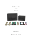
Parts supplied in EFMS100 system
• TX100 Sender unit
• RX100 Display unit
• Link cable (cable from sender unit to display unit)
• Tachometer sensor cable
• 9V battery enclosure with built-in ON/OFF switch (in case the
vehicle has no battery)
Optional accessories
• Temperature sensors (e.g. EGT and CHT)
• Fuel flow sensor (see www.enginemeter.com)
2 Detailed specifications
All parameters are refreshed every second.
2.1 Engine tachometer
All types of 2-stroke and 4-stroke engines are supported.
Table 1 - Tachometer range
Type of ignition system
Minimum (RPM) Maximum (RPM)
2 sparks per revolution
250
150000 with 1%
accuracy…
1 spark per revolution
500
1 spark per 2 revolutions
300000 with 2%
accuracy…
2.2 Engine hour meter
•
•
•
Counts the engine time in hours.
Resolution: 0.01 hour
Maximum: >8000 years…
2.3 Thermometers
Temperatures can be displayed in Celsius or Fahrenheit.
2.3.1
•
•
•
Temperatures using thermocouples
Up to 4 thermocouples
Support for both type J and type K thermocouples
Support both grounded and ungrounded thermocouples
Maximum temperatures:
• 800°C (1450°F) using type J thermocouples
• 1000°C (1800°F) using type K thermocouples
2.3.2
•
2
1000
Ambient temperature
Sensor built in the sender unit
3
2.4 Battery voltmeter
•
•
•
2.7 Regulated voltage +3.3V output
This feature is built in the sender unit
Resolution: 0.1 Volt
Range: see sender unit operating voltage range in section 2.10
•
•
•
•
The sender unit terminal is labeled “+3.3V OUT”
Can help the implementation of auxiliary inputs
Maximum output (sourcing current only / no sinking current) current
= 10mA !!!
Do not use unless you know exactly what you are doing
2.5 Fuel flow (optional sensor)
Fuel information based on fuel flow sensor inserted in the fuel line between
the tank and the engine.
The following parameters can be displayed:
• Fuel flow
• Fuel used
• Fuel onboard
• Time to tank empty
• Distance to tank empty
2.8 Timer
•
•
•
•
See section “5.9 FUEL FLOW menu” for detailed information
•
2.6 Auxiliary inputs
•
•
•
•
•
•
•
•
•
Many applications:
o Low fuel level detector (float switch)
o Fuel level sensor (e.g. using a resistive sensor)
o Thermistor (NTC or other type) temperature sensor
o Etc…
2 inputs labeled “AUX1” and “AUX2”
Full range: 0 to 2.5V
Resolution: 12bits (4096 steps)
Out of range voltage protection: -20 to +20V will not damage the
unit
AUX1 is a high input impedance (floating) input. Leakage current <
50nA
AUX2 has a 1kOhm/1% resistor internally connected to a 2.5V
voltage reference and a 150Ohm/1% resistor is series with the
terminal.
Can display calibrated values in order to match the characteristics
of any sensor
See section “5.10 AUX1 INPUT and AUX2 INPUT menu” for
detailed information
4
Display format: HH:MM (Hours:Minutes)
Roll over to 00:00 after 99:99
2 modes of operation:
o Counts time
o Counts engine run time
2 options for the power up value
o Timer is reset (00:00)
o Timer is restored to its value before power down
2 options for timer start
o Starts immediately
o Starts when the engine is started
2.9 Alarms
•
•
Flashing LED on display unit
Up to 10 alarms can be programmed:
o Choice of the parameter monitored
o Alarm state (disabled, low alarm or high alarm)
o Alarm threshold
2.10 Power supply
The sender unit operates from a DC power source (typically a 12V battery).
Minimum operating voltage: 7V
Maximum operating voltage: 20V
Current consumption: 13mA (total sender unit + display unit)
Built in power supply protections:
• Protected against voltage spikes that can be caused by the starter
or the ignition of the engine.
• Short circuit protection. Protects the battery from failures of
electronic components inside the sender unit.
5
•
Reverse polarity protection up to 20V.
2.12.1 Using a 9V standard battery
2.11 Sender unit
Dimensions: 90mm x 66mm x 28mm (3.5 x 2.6 x 1.1 inches)
Weight: 90grams (3.2 ounces-US&UK)
2.12 Display unit
In case the engine does not have a battery (engine with manual start), a
standard 9V battery (size/format is called EN22 or 6LR61 or 6AM6) can be
used.
The table below provides the battery life type for the most common types of
batteries.
The battery life can be estimated by:
Dimensions: 95mm x 62mm x 28mm (3.7 x 2.4 x 1.1 inches)
Weight: 80grams (2.8 ounces-US&UK)
Battery life = Battery capacity / Current consumption
(in hours)
(in mA.hour)
(in mA)
Table 2 – Battery life
Battery type
Typical
capacity
(mA.hour)
9V Alkaline
600
9V Lithium
1200
(Lithium Manganese
Dioxide)
Battery life
(hours)
46
92
In order to receive a low battery warning for 9V batteries, it is recommended
to set the “POWER UP BATTERY TEST” parameter around 7.9V (see
section “5.5 GENERAL menu” for more information)
and
to add a “low alarm” on the battery voltage around 7.7V (see section “5.8
ALARMS menu” for more information).
6
7
Nickel Metal Hydride (NiMH) and Nickel Cadmium (NiCd) rechargeable
batteries are not recommended because of their low voltage (7.2V nominal
instead) and their low capacity (around 150mA.h for NiMH and even less for
NiCd).
Connecting thermocouples (TC1 to TC4) has no impact on the current
consumption.
The optional fuel flow sensor has a small impact on the current
consumption (about 7mA).
3 Installation
3.1 IMPORTANT !!!
The sender and display units must be protected from:
•
Excessive levels of vibrations
o The sender unit must be isolated from vibrations using a
foam
•
Excessive temperatures
o Do not mount the unit next to the engine cylinder
•
Projections of liquids: water, fuel, oil, etc...
•
Excessive radiated electrical perturbations
o Do not mount the unit near the ignition system
For your safety, make sure all cables are secured (typically with several
plastic cable ties)
3.2 Sender unit power and ground
3.2.1
GROUND
Connect the ground (i.e. one GROUND terminal) of the sender unit to the
chassis of the motor.
The preferred location on the chassis is near the thermocouples (e.g. EGT
and CHT).
The shield of the thermocouple cable is connected to the body of sensor
(and therefore to the chassis) and can be used to connect the ground of the
sender unit to the chassis.
In most cases the negative terminal of the battery is already connected to
the chassis.
Only if this is not the case (e.g. when using a 9V battery), connect the
negative terminal of the battery to the ground of the sender unit.
8
9
3.2.2
+POWER IN
This terminal provides power to the unit and is typical connected to the
positive terminal of the battery.
Switch
If the main switch of the motor cannot be used for this function, a dedicated
power switch should be added in series with this connection.
3.3 Link cable
To sender unit
Fuse
In order to protect the battery from short circuits (which could be caused by
damaged wires for example), it is strongly recommended to insert a fuse
in series with this connection.
The fuse should be as close as possible to the battery positive terminal.
To display unit
Example of inline fuse holder:
The link cable connects the sender unit to the display unit.
The cable should be connected to the sender unit as described in the table
below.
Wire
Shield
White
Red
Description: 30-Amp Inline Mini Blade-Type Fuse Holder
Vendor: www.radioshack.com
P/N: 270-1237
Table 3 – Link cable
Terminal on
sender unit
Ground
GROUND
Data from sender unit
DATA OUT
to display unit
Power provided by the
+VPWR OUT
sender unit to the
display unit
Function
Tip (T)
Connector pinout
The connector is a standard 3.5mm diameter (1/8 inch) analog audio stereo
connector (used on most headset). This type of connector is often called
“TRS connector” (Tip, Ring, Sleeve)
A fuse is not needed when using a 9V battery.
10
Connector
pinout
Sleeve (S)
Ring (R)
11
3.4 Tachometer cable
3.4.3
Spark plug type
Using a resistor spark plug is more than strongly recommended.
WRAP around
ignition wire
3.4.1
Connect
to sender unit
Sender unit side
3.5 Thermocouples (EGT, CHT, etc.)
The tachometer cable should be connected to the sender unit as described
in the table below.
Wire
Black
Red
Table 4 - Tachometer cable
Function
Terminal on sender unit
Ground
GROUND
Tachometer
TACH IN
pickup
WARNING: connecting the tachometer cable to another terminal may
damage the sender unit
3.4.2
Ignition wire side
On the other side of the cable, the pickup wire (red wire) should be
WRAPPED around the ignition wire.
Start with 2 turns. Increase the number of turns only if needed.
For most engines 3 or 4 turns around the spark plug wire works well. Be
sure to secure the wire with two (one on each side of the coil) plastic wire
ties (tie-wrap) so the tachometer cable stays securely wrapped around the
spark plug wire.
Issue
Reading “LOW” or lower than
expected
Reading “HIGH” or higher than
expected
This is because resistor spark plugs reduce electromagnetic interference
with on-board electronics (computers, radios, GPS, etc.).
Most spark plug vendors add the letter “R” in the designation of the spark
plug to indicate a resistor spark plug.
For example NGK "R" resistor spark plugs use a 5k ohm ceramic resistor in
the spark plug to suppress ignition noise generated during sparking.
NGK BR9ES is the resistor version of NGK B9ES.
Solution
Add (wrap) 1 turn
Remove (unwrap) 1 turn
12
A good source for EGT and CHT sensors is Westach: www.westach.com
By construction, thermocouples probes are either grounded or ungrounded:
• Grounded means that the thermocouple junction (located where the
temperature is measured) is connected to the body. Most
thermocouples are of the grounded type which is easier to produce.
Westach probes are of the grounded type.
• Ungrounded (or “isolated”) means the thermocouple junction is
isolated from the body of the probe.
For both grounded and ungrounded thermocouples
• Connect the positive wire of the thermocouple (white wire on
Westach probes) to the positive input of the sender unit (e.g.
+TEMP1 IN).
• Connect the negative wire (black wire on Westach probes) of the
thermocouple to the negative input of the sender unit (e.g. -TEMP1
IN).
ONLY for ungrounded (rare) thermocouples
• Connect the negative input of the sender unit
(e.g. -TEMP1 IN) to the ground of the sender unit.
Using cable extensions if the cable of the thermocouple is too short
Thermocouples wires are made of special materials.
13
For example, for a type K thermocouple, the negative wire is made of
Alumel and the positive wire is made of Chromel.
If you need to add an extension, use only an extension of the same type
(e.g. type K extension for a type K thermocouple).
4 Operation of the display unit
4.1 Using the navigation button
3.6 Fuel Flow Sensor (option)
At the heart of the meter is a precision turbine that rotates freely on robust
sapphire bearings. Chemically resistant ceramic magnets that are detected
through the chamber wall by a Hall Effect detector (magnetic field detector).
Wire
Shield
Red
Blue
Table 5 – Fuel Flow Sensor
Function
Terminal on sender unit
Ground
GROUND
Power provided by the
+VPWR OUT
sender unit to the fuel flow
sensor
Signal from fuel flow
FLOW IN
sensor to sender unit
The navigation button located on the side of the unit allows you to configure
and use the display unit.
The button has 3 functions:
1. Push up ▲
2. Press inward ◄
3. Push down ▼
4.2 Normal screens
There are 4 “normal screens”:
1. “Main screen”: 8 parameters (user configurable) shown with large
characters.
IMPORTANT: Detailed information on the installation is provided in the fuel
flow sensor installation guide.
st
2. “Column 1 screen”: The 4 parameters of the 1 column of the main
screen indicated with very large characters.
14
15
nd
3. “Column 2 screen”: The 4 parameters of the 2 column of the main
screen indicated with very large characters.
4.3 Display of an alarm condition
If an alarm condition occurs, it will be indicated by:
1. Alarm LED flashing
2. If the parameter is on the screen, its value will be displayed in
inverse video mode (clear characters on dark background)
4. “Secondary screen”: All the parameters not present on the main
screen indicated with normal characters.
If the parameter is not displayed in the normal screen currently selected, an
“alarm screen” will appear
Push ▲ or ▼ to toggle between the 4 normal screens.
The alarm screen will display all the alarms unless they are already
displayed on the normal screen currently selected.
The display will toggle between the normal screen and the alarm screen
every 4 seconds.
Main screen
Secondary screen
Column 1 screen
Column 2 screen
16
4.4 Display of very large numbers (rare)
The values of the parameters are displayed with up to 5 characters.
If the value is higher than 99999 or lower than -9999 it cannot be displayed
with the regular numbers.
In these rare cases the value is displayed using the “scientific notation”.
Examples:
• 123456 will be been displayed 123E3 (123 and add 3 zeros = 123000)
-890000 will be displayed -89E4 (-89 and add 4 zeros = -890000)
17
5 Configuration of the display unit
5.1 Main menu
From any normal screen, use ◄ to enter the menu mode.
Timeout
Whenever the unit is in menu mode, a timeout will return the unit to the
normal screen mode if the navigation button is not activated during more
than 10 seconds.
If a parameter is being modified but the modification has not been validated
by pressing ◄ the modification will be cancel.
Exiting menu mode quickly
In menu mode, press ◄ for 3 seconds to go back to normal screen mode.
If a parameter is being modified the modification will be cancel.
Use ▲ or ▼ to scroll through the menu lines.
Confirmation
“…” at the end of a line (e.g. “RESET ENGINE HOURS...”) indicates that a
confirmation will be requested before any modification is done.
Use ◄ to enter a (sub) menu or select a function.
Screen after pressing ◄
As usual, use ▲ or ▼ to select “YES” or “NO” and validated with ◄
18
19
Table 6 – MAIN NEMU
Menu title
BEFORE STARTING
STATISTICS
TIMER
GENERAL
ON MAIN SCREEN
SHORT NAMES
ALARMS
FUEL FLOW
AUX1 INPUT
AUX2 INPUT
Description
Functions useful before starting the engine
Record parameters minimum, average and
maximum
Set the various timer parameters
General settings
To select the parameters indicated on the main
screen
To define the short name (3 characters) of each
parameter
To setup alarms
Related to the fuel flow sensor
Settings of AUX1 IN (auxiliary 1 input)
Settings of AUX2 IN (auxiliary 2 input)
5.2 BEFORE STARTING menu
These functions are useful before starting the engine.
Table 7 – BEFORE STARTING menu functions
Function
INITIAL FUEL
VOLUME
Description
Used in conjunction with the fuel flow sensor.
Sets the initial volume of fuel in the tank.
This is the volume of fuel in the tank when the fuel
used is reset (see “RESET FUEL USED” ” in the
“FUEL FLOW” menu for more information).
The unit is VOLUME.
VOLUME is the unit used to set
“PULSE/VOLUME RATIO” in the “FUEL FLOW”
menu.
RESET TIMER
Resets the timer to 00:00 (Hours:Minutes)
See “TIMER” menu for more information on the
timer.
RESET FUEL USED
Used in conjunction with the fuel flow sensor.
Resets “FUEL FLOW PULSE COUNT” to 0.
Therefore “FUEL USED (VOL.)” is also reset to 0.
Therefore “FUEL ONBOARD (VOL.)” is set to
“INITIAL FUEL VOLUME”.
This function also resets the time period used to
calculate the average fuel flow. See “AVERAGE
FUEL FLOW” parameter for more information.
20
RESET STATISTICS
Resets all the statistical parameters (i.e.
minimum, average and maximum).
RESET
TIM.+FUEL+STATS
See “RESET TIMER”, “RESET FUEL USED” and
“RESET STATISTICS” in this menu.
21
5.3 STATISTICS menu
5.4 TIMER menu
Table 8 – STATISTICS menu functions
Function
SHOW STATISTICS
Description
Displays minimum (MIN.), average (AVG.) and
maximum (MAX.) for the 5 monitored parameters.
Memo: the timer format is HH:MM (Hours:Minutes).
Note: The timer is independent from the engine hour meter.
Table 9 – TIMER menu functions
Function
DISPLAY UNIT
POWER UP
TIMER COUNTS
STAT. OPERATES
STAT. PARAMETER 1
(to 5)
•
ALWAYS: The parameters are always taken
into account for the statistics.
•
WHEN ENGINE RUNNING: The parameters
are taken into account for the statistics only
when the engine is running. The detection of
engine running is provided by the tachometer.
Select the parameter monitored.
Changing the parameter monitored resets its
statistics without resetting the statistics of the 4
other parameters.
TIME TIMER
STARTS
START WITH
RPM: RPM
START W. RPM:
SECONDS
Description
• TIMER RESETS TO 00:00: at power up, the timer
is reset to 00:00.
• TIMER=PREVIOUS VALUE: at power up, the
timer continues from its previous value (i.e. before
the power down of the display unit).
Power up refers to the power up of the display unit.
• TIME: the timer simply counts the time.
• ENGINE RUN TIME: the timer counts only the
time when the engine is running. The detection of
engine running is provided by the tachometer.
This setting is only relevant if “TIMER COUNTS” =
“TIME”
• “IMMEDIATELY”: The timer will start immediately.
• “WITH ENGINE RPM”: The timer will start when
the engine RPM is above “START WITH RPM:
RPM” (see below in this menu) during more than
“START W. RPM: SECONDS” (see below in this
menu). After the timer is started, it will continue
regardless of the engine RPM.
This setting is only relevant if
“TIMER COUNTS” = “TIME” and “TIME TIMER
STARTS” = “WITH ENGINE RPM”
“START WITH RPM: RPM” is used to start the timer
automatically based on the engine RPM. See “TIME
TIMER STARTS” in this menu for more information.
This setting is only relevant if
“TIMER COUNTS” = “TIME” and “TIME TIMER
STARTS” = “WITH ENGINE RPM”
“START W. RPM: SECONDS” is a time in seconds
used to start the timer automatically based on the
engine RPM. See “TIME TIMER STARTS” in this
menu for more information.
22
23
5.5 GENERAL menu
5.6 ON MAIN SCREEN menu
Table 10 – GENERAL menu functions
Function
DISPLAY CONTRAST
FACTORY RESET...
RESET ENGINE
HOURS...
TEMPERATURE UNITS
SPARK(S) PER REV.
TC1 THERMOCOUPLE
TYPE
TC2 THERMOCOUPLE
TYPE
TC3 THERMOCOUPLE
TYPE
TC4 THERMOCOUPLE
TYPE
POWER UP BATTERY
TEST
Description
Sets the contrast of the display
Warning: This resets ALL the configuration
parameters to factory default value.
Only the engine hour meter is not reset.
Warning: This resets the engine hour meter
to zero (0).
• CELSIUS: all temperatures will be
displayed in Celsius
• FAHRENHEIT: all temperatures will be
displayed in Fahrenheit
• 2 SPARKS PER REV.: for engines with
ignition generating 2 sparks per revolution
• 1 SPARK PER REV. : for engines with
ignition generating 1 spark per revolution
• 1 SPARK PER 2 REV. : for engines with
ignition generating 1 spark per 2
revolutions
• TYPE J: use when the thermocouple
connected to TC1 input is type J.
• TYPE K: use when the thermocouple
connected to TC1 input is type K.
Notes:
Most CHT sensors are type J.
Most EGT sensors are type K.
Same as above for TC2 input.
Select a parameter for each location of the main screen.
LINE 1/COLUMN 1
LINE 1/COLUMN 2
LINE 2/COLUMN 1
LINE 2/COLUMN 2
LINE 3/COLUMN 1
LINE 3/COLUMN 2
LINE 4/COLUMN 1
LINE 4/COLUMN 2
Example (factory default):
Same as above for TC3 input.
Same as above for TC4 input.
A warning message is displayed at power up
if the battery voltage is below this value. This
function is mostly useful if the power supply
source is a 9V battery.
24
25
Function
5.7 SHORT NAMES menu
Use this menu to set a custom 3 character name for the parameter that can
be displayed on the main screen. This allows the user to select a 3
character name that best represents the parameter to them.
TC4
TEMPERATURE
AMBIENT
TEMPERATURE
AUX1 INPUT
AUX2 INPUT
Factory
default
name
TC4
Description
TA
Ambient temperature measured by the
sender unit.
Value based on the voltage applied to
the AUX1 input (“AUX1 IN”).
See “AUX1 INPUT” menu for more
information.
Idem with AUX2 input.
AX1
AX2
Idem with TC4
Table 12 – SHORT NAMES menu functions using the fuel flow sensor
Table 11 – SHORT NAMES menu functions
Function
ENGINE
TACHOMETER
Factory
default
name
RPM
ENGINE HOURS
HRS
TIMER (HH:MM)
TIM
Description
FUEL FLOW
PULSE COUNT
BAT
TC1
TEMPERATURE
TC2
TEMPERATURE
TC3
TEMPERATURE
EGT
Factory
default
name
FPC
Engine tachometer.
The value is indicated in Revolutions
Per Minute.
Engine hour meter for engine
maintenance. Measures the engine run
time.
Timer.
Refer to the menu “TIMER” for more
information.
BATTERY
VOLTAGE
Function
The display format is Hours:Minutes.
Power supply voltage on the pin
+POWER IN.
CHT
The value is indicated in volts.
Temperature provided by the
thermocouple connected to TC1 input.
Idem with TC2
TC3
Idem with TC3
26
FUEL USED
(VOL.)
USE
Description
Number of pulses generated by the fuel
flow sensor. The number of pulses is
proportional to the volume of fuel used.
This parameter is useful for the
calibration or the test of the fuel flow
sensor.
Volume of fuel measured by the fuel
flow sensor.
“FUEL USED (VOL.)” =
“FUEL FLOW PULSE COUNT”
/ “PULSE/VOLUME RATIO”
The unit is VOLUME (e.g. liters or US
gallons).
VOLUME is the unit used to set
“PULSE/VOLUME RATIO” in the
“FUEL FLOW” menu.
27
Function
FUEL ONBOARD
(VOL.)
Factory
default
name
FOB
Description
Function
Volume of fuel in the fuel tank.
TIME TO EMPTY
Factory
default
name
TMT
“FUEL ONBOARD (VOL.)” =
“INITIAL FUEL VOLUME”
- “FUEL USED (VOL.)”
FUEL ONBOARD
(% INIT.)
FUEL FLOW
(VOL./HOUR)
%OB
FFC
The unit is VOLUME.
VOLUME is the unit used to set
“PULSE/VOLUME RATIO” in the
“FUEL FLOW” menu.
Quantity of fuel in the fuel tank.
The unit is % of the “INITIAL FUEL
VOLUME”.
“FUEL ONBOARD” / “FUEL FLOW”
TIME TO MT AT
AVG FF
TMA
FFA
“AVERAGE FUEL FLOW” =
The display format is Hours:Minutes.
Meaning: Time to tank empty (MT)
using the average (AVG) fuel flow (FF)
Same as “TIME TO EMPTY” but using
the “AVERAGE FUEL FLOW” instead
of the current “FUEL FLOW”.
“TIME TO MT AT AVG FF” =
“FUEL ONBOARD”
/
“AVERAGE FUEL FLOW”
The measurement is done during the
“AVERAGING TIME (SEC.)” (set with
the “FUEL FLOW” menu).
AVERAGE FUEL
FLOW
The current fuel flow is used to
calculate the amount of time until the
tank is empty:
“TIME TO EMPTY” =
“INITIAL FUEL VOLUME” is set in the
“BEFORE STARTING” menu.
Current fuel flow measured by the fuel
flow sensor.
The unit is VOLUME per hour.
VOLUME is the unit used to set
“PULSE/VOLUME RATIO” in the
“FUEL FLOW” menu.
Average fuel flow calculated with:
Description
DISTANCE TO
EMPTY
DMT
The display format is Hours:Minutes.
The current fuel flow is used to
calculate the distance until the tank is
empty:
“DISTANCE TO EMPTY” =
“TIME TO EMPTY”
x
“SPEED”
“FUEL USED” / TIME
Where TIME is the engine run time
since the fuel used was reset using
“RESET FUEL USED”.
28
The unit is the unit used to set
“SPEED” in the menu “FUEL FLOW”.
29
Function
DIST TO MT AT
AVG FF
Factory
default
name
DMA
Description
Meaning: Distance (DIST) to tank
empty (MT) using the average (AVG)
fuel flow (FF)
Same as “DISTANCE TO EMPTY” but
using the “AVERAGE FUEL FLOW”
instead of the current “FUEL FLOW”.
Step 3: Select the parameter
monitored by this alarm
Step 4: Select alarm threshold
Each alarm can be set on any
parameter defined in the menu
“SHORT NAMES”.
“DIST TO MT AT AVG FF” =
“TIME TO MT AT AVG FF”
x
“SPEED”
The unit is the unit used to set
“SPEED” in the menu “FUEL FLOW”.
5.9 FUEL FLOW menu
5.8 ALARMS menu
Table 13 – FUEL FLOW menu functions
Step 1: Select one of the 10
available alarms
Step 2: Select the type of alarm
Each alarm can be:
• “ALARM DISABLED” : the
parameter is not tested
• “LOW ALARM”: alarm if the
parameter is less or equal to the
threshold
• “HIGH ALARM”: alarm if the
parameter is higher or equal to
the threshold
30
Function
PULSE/VOLUME RATIO
Description
Set the characteristic of the fuel flow
sensor.
See fuel flow calibration procedure below.
AVERAGING TIME (SEC.)
Set the period of time (in seconds) used to
calculate the fuel flow rate: “FUEL FLOW
(VOL./HOUR)”
SPEED (DISTANCE/h)
Set the speed of the machine. This value is
used to estimate the “DISTANCE TO
EMPTY”.
Enter the value in kilometers per hour if you
would like the “DISTANCE TO EMPTY”
indicated in kilometers.
Enter the value in miles per hour if you
would like the “DISTANCE TO EMPTY”
indicated in miles.
For more information see “DISTANCE TO
EMPTY” in the menu “SHORT NAMES”.
31
BUTTON PUSH DOWN
Assign the function of the navigation button
in normal screens when the button is
pushed down.
•
•
“TOGGLE SCREEN”: pushing the
navigation button down toggles the
normal screens (“main screen”, “column
1 screen”, “column 2 screen” and
“secondary screen”)
“CHANGE SPEED”: pushing the
navigation button down provides a fast
method to change the SPEED
parameter described in this menu.
5.9.1
Calibration of the fuel flow sensor
The calibration procedure is required to ensure the best accuracy of the
measurements provided by the flow sensor.
The calibration procedure is also very important to make sure the sensor
is working properly.
For maximum accuracy several parameters are important for the calibration.
1. Viscosity of the fuel
2. Flow rate
3. Installation of the sensor
It is therefore important to calibrate the sensor by running the engine in
normal operating conditions.
5.9.1.1
Calibration procedure
1. Install the sensor according to its installation guide.
2. Fill the fuel tank and make sure that you will be able to fill it with the
exact same amount of fuel next time.
3. Reset the parameter “FUEL FLOW PULSE COUNT” using the
function “RESET FUEL USED” in the menu “BEFORE STARTING”.
4. Run the engine in normal conditions. For best accuracy you should
burn at least 50% of the volume of the tank.
5. Write down the value of “FUEL FLOW PULSE COUNT”.
6. Fill the fuel tank back to its initial amount of fuel. This time you
need to fill the tank with a graduated container so that you know
the exact amount of fuel you have added to fill the tank. This
amount of fuel is the amount of fuel burnt during the calibration
procedure.
32
33
7. Using the “FUEL FLOW” menu set “PULSE/VOLUME RATIO” to
the value calculated with
(FUEL FLOW PULSE COUNT) / (Volume of fuel burnt)
5.10 AUX1 INPUT and AUX2 INPUT menus
This menu allows displaying either the “RAW VALUE” or the “CALIBRATED
VALUE” defined below.
This value of “PULSE/VOLUME RATIO” calculated should be within +/-5%
of the value provided in the installation guide of the fuel flow sensor. If this
is not the case, it means that the fuel flow sensor is not working properly.
Typically this means that the sensor is not installed properly. In this case,
you should not use the value calculated but instead, you should fix the
problem.
5.9.1.2
Example
“FUEL FLOW PULSE COUNT” after running the engine = 35484
Volume of fuel burnt during the calibration procedure = 5.17 liters
The “PULSE/VOLUME RATIO” should be set to
35484 / 5.17 = 6863 pulses per liter
Figure 1 – AUX inputs block diagram
5.10.1.1 ADC block characteristic
The ADC block is a 12-bit Analog to Digital Converter.
12
12 bits provide 2 = 4096 values (0 to 4095).
The input voltage range of the ADC is 0 to 2.5V.
A voltage of 0V (or below) is converted into a RAW VALUE of 0.
A voltage of 2.5V (or above) is converted into a RAW VALUE of 4095.
A voltage between 0 and 2.5V is converted into a RAW VALUE proportional
to the voltage.
34
35
5.10.2 CALIBRATION block characteristic
The characteristic of the calibration block is defined by 11 data points and 2
values (MIN CALIBRATED VALUE and MAX CALIBRATED VALUE).
By definition,
100% = “MAX CALIBRATED VALUE” – “MIN CALIBRATED VALUE”
The data points must be strictly increasing or strictly decreasing.
The following values are used as an example:
This means:
Table 14 – Example of calibration
Data
point
1
2
3
4
5
6
7
8
9
10
11
Parameter
RAW
RAW
RAW
RAW
RAW
RAW
RAW
RAW
RAW
RAW
RAW
As shown on the above example:
• Raw values below “RAW AT CAL=MIN” are displayed with a
calibrated value of “MIN CALIBRATED VALUE”.
• Raw values above “RAW AT CAL=MAX” are displayed with a
calibrated value of “MAX CALIBRATED VALUE”.
• For raw values between 2 data points a linear interpolation is used
to provide the calibrated value.
RAW(1) < RAW(2) < … < RAW(10) < RAW(11)
or
Value
(example)
500
1448
1841
2143
2397
2621
2823
3009
3183
3346
3500
AT CAL=MIN
AT CAL=MIN+10%
AT CAL=MIN+20%
AT CAL=MIN+30%
AT CAL=MIN+40%
AT CAL=MIN+50%
AT CAL=MIN+60%
AT CAL=MIN+70%
AT CAL=MIN+80%
AT CAL=MIN+90%
AT CAL=MAX
RAW(1) > RAW(2) > … > RAW(10) > RAW(11)
If this condition is not met, “INVAL” (invalid characteristic) will be indicated
on the main screen.
MAX CALIBRATED VALUE
+100%
+90%
CALIBRATED VALUE
+80%
+70%
+60%
+50%
DATA POINTS
+40%
+30%
+20%
LINEAR INTERPOLATION
+10%
MIN CALIBRATED VALUE
+%
0
500
1000
1500
2000
2500
3000
3500
4000
RAW VALUE
36
37
CALIBRATION DEFINITION
Table 15 – AUX1 INPUT and AUX2 INPUT menu functions
Function
Description
DISPLAY
Choose the value that will appear on the
main screen:
• RAW VALUE
• CALIBRATED VALUE
Set the period of time used to calculate
the value.
Minimum calibrated value
AVERAGING
TIME (SEC.)
MIN CALIBRATED
VALUE
MAX
CALIBRATED
VALUE
RAW AT
CAL=MIN
RAW AT
CAL=MIN+10%
RAW AT
CAL=MIN+20%
RAW AT
CAL=MIN+30%
RAW AT
CAL=MIN+40%
RAW AT
CAL=MIN+50%
RAW AT
CAL=MIN+60%
RAW AT
CAL=MIN+70%
RAW AT
CAL=MIN+80%
RAW AT
CAL=MIN+90%
RAW AT
CAL=MAX
5.10.3 Example of application
Data
point
In this example, the AUX1 input is used for fuel level indication.
A fuel level sender provides a voltage which is proportional to the height of
the fuel in the tank.
The user wants to have the fuel onboard indicated in % of the tank volume.
The capacity of the tank is 10 liters.
Because the section of the tank varies (e.g. wide at the bottom and narrow
at the top) a careful calibration is required.
Step 1:
• Set “MIN CALIBRATED VALUE” to 0 (0% = tank empty)
• Set “MAX CALIBRATED VALUE” to 100 (100% = tank full)
Maximum calibrated value
Raw value when the calibrated value is
MIN CALIBRATED VALUE
Raw value when the calibrated value is
MIN CALIBRATED VALUE + 10%
Same with +20%
1
Same with +30%
4
Same with +40%
5
Step 3:
• Write down the “RAW VALUE” indicated on the main screen
• Add 10% of fuel. In this example, 10% of 10 liters is 1 liter.
Same with +50%
6
Step 4: Repeat Step 3 until the tank is full.
Same with +60%
7
Step 5: Using the AUX1 INPUT menu, enter the 11 data points written down
starting with “RAW AT CAL=MIN” and ending with “RAW AT CAL=MAX”.
Same with +70%
8
Same with +80%
9
Step 6: Set “DISPLAY” to “CALIBRATED VALUE” (see “AUX1 INPUT”
menu)
Same with +90%
10
The value indicated on the main screen is now correct.
Raw value when the calibrated value is
MAX CALIBRATED VALUE
11
38
2
3
Step 2:
• Make sure the tank is empty
• Make sure “AUX1 INPUT” is displayed on the main screen (see
“ON MAIN SCREEN” menu)
• Set “DISPLAY” to “RAW VALUE” (see “AUX1 INPUT” menu)
39
6.2 Tachometer
6 Troubleshooting
Value indicated
“LOW”
6.1 Incorrect values
Value
indicated
LOW
HIGH
RANGE
?????
ERROR
----WAIT
INVAL
Meaning
Solutions
The parameter cannot be
measured because it is too low.
The parameter cannot be
measured because it is too
high.
The sensor provides a signal
which is out of range and
therefore cannot be measured.
The value cannot be displayed
because no data was received
by the display unit.
The value cannot be displayed
because the data was not
received properly.
Make sure that the sensor
is connected to the sender
unit and that the parameter
measured is within the
range specified in this
document.
The display unit needs more
data from the sender unit.
The value cannot be displayed
because the engine has not
been running since the “FUEL
USED” was reset.
= INVALID
The parameter cannot be
calculated because the
characteristic of the sensor
provided is invalid.
40
Make sure the link cable is
properly connected.
Make sure the link cable is
properly connected.
Make sure the link cable is
not too close to the ignition
system of the engine.
Wait a few seconds.
or a value
abnormally low
“HIGH”
Solutions
1. Make sure that the sensor is connected to the sender
unit and that the parameter measured is within the
range specified in this document.
2. Make sure the wraps around the ignition wire are tight
3. Make sure the ignition wire is not shielded.
4. Increase the number of turns of the pickup wire
around the ignition wire.
• Decrease the number of turns of the pickup wire
around the ignition wire.
or a value
abnormally high
6.3 Temperatures
6.3.1
Thermocouples
Value indicated
Value abnormally
low
The value will be displayed
when the engine is started.
Value abnormally
high
Correct the characteristic of
the sensor in order to meet
the requirements listed in
this document.
The value
decreases when
the temperature
increases
Temperature
readings are erratic
Issue
A type K
thermocouple is used
but the unit is
configured for type J.
A type J
thermocouple is used
but the unit is
configured for type K.
Solution
Change the configuration to
match the type of
thermocouple used.
The polarity is
reversed.
Swap the positive wire with
the negative wire to correct
the polarity.
Bad grounding
See section 3.5
41
Change the configuration to
match the type of
thermocouple used.