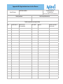
1
AVANTI FALL PROTECTION SYSTEM
User’s Manual and Installation Instructions
ANSI
AVANTI Fall Protection System
User‘s Manual and Installation Instructions
All safety statements, specifications, hazards, and inspections defined shall apply only to the version of product specified in this manual. The images and
representations in this manual may vary slightly from the actual product you are using; please review your product label(s) to ensure a proper match.
Date of publication:
2nd Edition: Febuary 2013
Revision 2: 20/7/13
Manufacturer:
2
Avanti Wind Systems A/S
Høgevej 19
3400 Hillerød
Denmark
P: (+45) 4824 9024
F: (+45) 4824 9124
E: [email protected]
I: www.avanti-online.com
ANSI
Sales & Services:
Australia
Avanti Wind Systems PTY LTD P: +61 (0) 7 3902 1445
China
Avanti Wind Systems P: +86 21 5785 8811
Denmark
Avanti Wind Systems A/S P: +45 4824 9024
Germany
Avanti Wind Systems GmbH P: +49 (0) 41 21-7 88 85 – 0
Spain
Avanti Wind Systems SL P: +34 976 149 524
UK
Avanti Wind Systems Limited P: +44 0 1706 356 442
USA
Avanti Wind Systems,Inc P: +1 (262) 641-9101
India
Avanti Wind Systems,PL P: +91 44 6455 5911
Index
1
2
3
4
5
6
7
8
9
Caution . . . . . . . . . . .
Danger . . . . . . . . . . . .
Description of equipment .
3.1 Purpose . . . . . . . . .
3.2 Function . . . . . . . . .
3.3 Component overview .
Daily inspection . . . . . . .
Directions for use . . . . . .
Maintenance . . . . . . . .
Annual inspection . . . . .
Ordering spare parts . . . .
Marking . . . . . . . . . . .
.
.
.
.
.
.
.
.
.
.
.
.
.
.
.
.
.
.
.
.
.
.
.
.
.
.
.
.
.
.
.
.
.
.
.
.
.
.
.
.
.
.
.
.
.
.
.
.
.
.
.
.
.
.
.
.
.
.
.
.
.
.
.
.
.
.
.
.
.
.
.
.
.
.
.
.
.
.
.
.
.
.
.
.
.
.
.
.
.
.
.
.
.
.
.
.
.
.
.
.
.
.
.
.
.
.
.
.
.
.
.
.
.
.
.
.
.
.
.
.
.
.
.
.
.
.
.
.
.
.
.
.
.
.
.
.
.
.
.
.
.
.
.
.
.
.
.
.
.
.
.
.
.
.
.
.
.
.
.
.
.
.
.
.
.
.
.
.
.
.
.
.
.
.
.
.
.
.
.
.
.
.
.
.
.
.
.
.
.
.
.
.
.
.
.
.
.
.
.
.
.
.
.
.
.
.
.
.
.
.
.
.
6
6
7
7
8
8
8
8
10
10
10
11
Installation manual
0 Fitting instructions . . . . . . . . . . . . . . . . . . . . . .
1
11 Inspection before initial use . . . . . . . . . . . . . . . . .
12
15
Appendix A: The Improved AVANTI Fall Protection System
Type 2000/2002 . . . . . . . . . . . . . . . . . . . . . . . . . .
Appendix B: Avanti Shock Absorber . . . . . . . . . . . . . .
Appendix C: Inspection Before Initial Use Report . . . . . .
Appendix D: Checklist /Visual Test for the Runner . . . . . .
Appendix E: Registration Form for the Runner . . . . . . . . .
16
17
18
20
22
3
Limited Warranty
Avanti Wind Systems A/S warrants that commencing from the date of
INCLUDING, BUT NOT LIMITED TO, ANY IMPLIED WARRANTY OR CON-
shipment to the Customer, and continuing for a period of the longer
DITION OF MERCHANTABILITY, FITNESS FOR A PARTICULAR PURPOSE,
of 365 days thereafter, or the period set forth in the standard AVANTI
NON-INFRINGEMENT, SATISFACTORY QUALITY, COURSE OF DEALING,
warranty, the Fall Protection System (“Product”) described in this
LAW, USAGE OR TRADE PRACTICE ARE HERBY EXCLUDED TO THE MAX-
Manual will be free from defects in material and workmanship under
IMUM EXTENT PERMITTED BY APPLICABLE LAW AND ARE EXPRESSLY
normal use and service when installed and operated in accordance
DISCLAIMED BY AVANTI. IF, PURSUANT TO ANY APPLICABLE LAW, TO
with the provisions of this manual.
THE EXTENT AN IMPLIED WARRANTY CANNOT BE EXCLUDED AS PROVIDED IN THIS LIMITED WARRANTY, ANY IMPLIED WARRANTY IS LIM-
4
This warranty is made only to the original user of the Product. The
ITED IN TIME TO THE SAME DURATION AS THE EXPRESS WARRANTY
sole and exclusive remedy and the entire liability of AVANTI under
PERIOD SET FORTH ABOVE. BECAUSE SOME STATES DO NOT PERMIT
this limited warranty, shall be, at the option of AVANTI, a replacement
LIMITATIONS ON THE DURATION OF IMPLIED WARRANTIES, THIS MAY
of the Product (including incidental and freight charges paid by the
NOT APPLY TO A GIVEN CUSTOMER. THIS LIMITED WARRANTY GIVES
customer) with a similar new or reconditioned Product of equivalent
CUSTOMER SPECIFIC LEGAL RIGHTS, AND CUSTOMER MAY HAVE
value, or a refund of the purchase price if the Product is returned to
OTHER LEGAL RIGHTS UNDER APPLICABLE LAWS. This disclaimer shall
AVANTI, freight and insurance prepaid. The obligations of AVANTI are
apply even if the express warranty fails of its essential purpose.
expressly conditioned upon return of the Product in strict accordance
with the return procedures of AVANTI.
In any cases of dispute the English original shall be taken as
authoritative.
This warranty does not apply if the Product (i) has been altered without the authorization of AVANTI or its authorized representative; (ii)
has not been installed, operated, repaired, or maintained in accordance with this Manual or other instructions from AVANTI; (iii) has been
subjected to abuse, neglect, casualty, or negligence; (iv) has been
furnished by AVANTI to Customer without charge; or (v) has been sold
on an “AS-IS” basis.
Except as specifically set forth in this Limited Warranty, ALL EXPRESS
OR IMPLIED CONDITIONS, REPRESENTATIONS AND WARRANTIES,
5
1 Caution
a) A competent person is familiar with and is trained within the AVANTI
Fall Protection System, and the following standards: EN 363, EN 353-1,
ANSI-ASC A14.3-2008, ANSI/ASSE Z359.1-2007, CAN/CSA Z259.1201 and CAN/CSA Z259.2.1-98. An AVANTI Fall Protection Technician
has succesfully participated in the AVANTI Fall Protection course and is
considered competent. A user is familiar with the correct usage of the
AVANTI Fall Protection System and has had an introduction to personal
protection equipment.
b) Assembly, maintenance and testing of the Fall Protection System may
only be performed by a competent person.
c) Users are obliged to read and understand this User’s Manual.
d) A copy of the User’s Manual must be handed out to the fall protection
users and must be available for reference.
6
2 Danger
a) The Fall Protection System may not be used by persons under influence of alcohol or drugs that may jeopardize working safety.
b) Only people instructed to the AVANTI Fall Protection System by a
qualified trainer may use the system.
c) The owner must ensure that a rescue plan that deals with any emergencies that could arise during work is in place and that the users are
familiar with this.
d) If any damage or faults are found during operation, or in case of circumstances which may jeopardize safety:
- Immediately stop the work in progress
- Contact the authority responsible e.g. the turbine owner or the site
foreman.
e) If more than one person is trusted with one of the above tasks, the
employer shall appoint a supervisor in charge of operation.
e) No warranty is provided against damage resulting from reconstruction
or modification of equipment or use of non-original parts which are not
approved by the manufacturer.
f) If the Fall Protection System is re-sold outside the original country of
destination the reseller shall provide instructions for use, for mainte-
f) The Fall Protection System may not be used outside its limitations, or
for any purpose other than for which it is intended.
nance, for periodic examination and for repair in the language of the
country in which the product is to be used.
g)Please insure the ladder system with the Fall Protecting
System is capable of supporting: for USA: not less than 5000 lb (22,6kN)
static load, for Canada: not less than 27 kN, for EU: not less than 15 kN
g) The AVANTI fall protection runner should be treated as personal protection equipment.
h) Keep a distance of 20 feet (6 meters) between each user during ascent
and descent.
h) Always remove the runner from the rail when not in use; the runner is not
intended to be parked on the rail when freely suspended.
i)
In the first two meters the user may not be protected against hitting the
ground. Take precautions.
i)
The system is only to be operated by users being properly trained in
daily inspections, working at heights and practical operation of the
system.
j)
Prior to initial use a competent person must inspect the system.
j)
For optimal operation, enhanced safety and better climbing ergonomics;
the climber is recommended to maintain a minimum distance of 4” (10
cm) from torso to ladder during regular climb. A good climbing position
is easily obtained by leaning the upper back against the tower.
k) Clean off any oil, grease, or residue on the rail.
l)
If oil, grease, chemicals or residue has leaked onto the shock absorber
or in any kind been in contact with the webbing, have an AVANTI fall
protection technician replace the shock absorber.
m) After 5 years of use replace the shock absorber. Date of manufacture
is printed on the shock absorber label.
n) Operation temperature -31 Deg / +140 Fahrenheit(-35 / +60 Celcius).
o) In connection with the Fall Protection System only full body harnesses
approved according to EN 361, ANSI Z359.1 and CSA Z259.10 may be
used.
v) It’s necessary to use alternative fall protection when
stepping on or off the ladder. The runner must not be disconnected
from the rail before establishing alternative fall protection.
The runner must always be attached to the D-ring in the harness
before connecting or disconnecting it to the rail.
w) When working or resting at the ladder it’s essential that the user
utilizes alternative safety. The AVANTI Fall Protection System is only
tested as fall arrest safety when ascending or descending the ladder.
x) Don’t ever twist the shock absorber, it may cause the system to fail.
The owner must verify the need for 3rd party fall protection device
inspections with the local authority and comply with the standards
specified.
p) The complete Fall Protection System has been manufactured and
tested according to applicable parts of EN 353-1, CANCSA Z259.1-98
and ANSI Z359.1
q) Ladders supplied by AVANTI comply with the requirements of EN 131,
EN ISO 14122 and ANSI 14.3
r) The Avanti supplied Carabiner is tested according to CSA , ANSI
Z359.1-2007 and EN 362 requirements.
3 Description of Equipment
3.1 Purpose
s) All parts and units have been especially developed for the AVANTI Fall
Protection System Type 2002 and as such cannot be used in other Fall
Protection Systems.
t) These instructions must be kept together with the Fall Protection
System.
u) Whenever using the AVANTI Fall Protection System it’s very important
to always make sure that the harness is connected by the D-ring
complying with the demands for climbing in vertical fall arrest safety
systems on ladders. This infomation shall be described in the user
manual from your harness supplier.
The Fall Protection Devices in this User’s Manual serves the
following purposes:
- The Fall Protection System is intended for use during ascent and
descent on stationary ladders installed in towers, pylons, well shafts,
manholes, etc.
- The Fall Protection System is a safety device traveling on a rail which
prevents free fall during climbing.
- The fall protection safety rail is designed for permanent installation in
one place.
- The Fall Protection System can be mounted on different shapes and
brands of ladders, as long as approval is issued by AVANTI according to
section 10d.
The Fall Protection System is not designed for:
- Securing horizontally.
- Securing Equipment.
7
3.2 Function
The Fall Protection System is comprised of a safety rail mounted on a
ladder and a runner which can be clicked onto the rail. The user attaches
the runner to their harness by means of an integrated shock absorber and
carabiner. When starting the climb the user clicks the runner. When climbing the runner glides upward on the safety rail. In case the user experiences
a fall the runner will lock onto the safety rail and arrest the fall.
3.3 Component overview:
4 Daily Inspection
1) Before any use the runner must be checked for visual damage, wear
and tear, and other defects, according to appendix B.
2) During ascent look for visible damage and loose parts along with
loose bolts on ladder, rail or joints.
3) Equipment with defects or equipment that leaves doubt concerning safe
use must be checked by a competent person.
Rail
Guide ridge
STOP
STOP if the runner looks defective / or parts are
missing, do not use it.
Runner
8
5 Directions for Use
STOP
Rail and runner on ladder
Runner with shock absorber pack and carabiner.
DANGER!
• The runner, the shock absorber pack, and the carabiner comprise a
safety system. Never adapt, extend, or in any way change this system.
• The runner may only be used if the bottom left steel tap lock has
popped out in lock position.
• The arrow on the runner must point upward – otherwise it will not block
a fall.
Correct mounting
Incorrect mounting
1
2
Instructions:
a) Before using this Fall Protection System make sure to wear an approved harness worn in accordance to the manufacturer’s instructions.
While lifting the break leaver, tilt the runner so both runner sides are
around each side of the safety rail (2).
b) With the arrow on the runner portion of the Fall Arrest System pointing
in the “UP” direction, and the rest of the unit not twisted, fasten the
carabiner to the user’s body harness at the chest D-ring connection
on the harness. Consult the harness manufacturer’s manual for an
approved fall arrest connection.
Always make sure that the carabiner of the Fall Protection
System is connected to the D-ring of the full body harness when
attaching/detaching the runner.
c) With the arrow on the plate pointing upwards the runner is clicked onto
the safety rail. (see picture 1)
Open runner by pushing bottom left steel tap lock and pull left and right
runner side apart.
Place one of the runner sides on its respective safety rail side with the runner arrow pointing upward (1).
3
Push the two runner body parts together until the bottom left steel tap
lock pops back in position and locks the runner body. Make sure it is
locked correctly (3).
Detach runner by pushing the bottom left steel tap and pull the
runner sides apart.
9
Before detaching assure you are in a safe area or secured by
another fall protection device.
DANGER!
10
6 Maintenance
STOP
a)
If the fall protection
System has blocked a fall take the
ladder and runner out of use. Contact a Fall
Protection Technician so they can inspect the affected ladder/rail and the runner.
b)
When ever using the AVANTI Fall Protection System it is
very important to always make sure, that the harness is
connected by the D-ring complying with the demands
for climbing vertical fall arrest safety systems on lad
ders. This information shall be described in the user
manual from your harness supplier.
a) Keep all parts free of oil, grease, paint and chemicals.
c) To ensure safety it is very important that the runner is attached
to the correct D-ring of the harness before connecting to or
disconnecting from the the ladder/fall arrest system.
This way the user can’t drop the runner. Only connect or
disconnect the runner from the rail while standing on a safe
support or adequately tied-off with secondary fall protection
system.
d) When working or resting at the ladder it is essential that
the user uses a secondary fall protection system.
The AVANTI Fall Protection System is only approved as fall
arrest safety when ascending or descending the ladder.
WARNING!
• The fall arrester shall be attached to no more than one personal
fall-arrest system.
•
Use is not suitable when the user is positioned on an unstable surface, fine-grain material, or particulate.
b) Never place liquids or sharp objects in the vicinity of the Fall Protection
System as these may damage the equipment.
c) The shock absorber pack can be cleaned using a weak detergentsolution and a soft brush. Subsequently, rinse with clean water.
d) If the system gets wet let the shock absorber pack air-dry naturally.
Do not use any kind of heating.
e) Store runner out of direct sunlight and protected from heat and dust.
At minimum, every 12 months, the Fall Protection System
should be inspected by an AVANTI Fall Protection Technician.
7 Annual Inspection
Once a year a competent person must inspect the fall protection system
according to ANSI Z359.2-2007. If the Annual tests are not performed this
will void the warranty and AVANTI will renounce all liability and claims that
may appear. AVANTI conducts Fall Protection Courses on a regular basis. If
interested, contact AVANTI.
8 Ordering Spare Parts
When parts are found to be missing, stop working - the system must be
taken out of use!
Rail and ladder: Contact a competent person and let him/her replace/repair the missing parts and conduct a Fall Protection System inspection.
Runner: Contact AVANTI and let them replace/repair the missing parts and
conduct a runner inspection.
9 Marking
Upward direction when runner is attached to rail
Read instructions before use
Runner production no.
Compliance
AVANTI product name
Standard no.
Runner rating plate
EEC-notified body no.
Standard no.
Production batch no.
Read instructions before use
Rail rating plate
Shock absorber pack label
11
Installation manual
10 Fitting Instructions
a) A competent person must be in charge of the Fall Protection System
installation. The competent person takes full responsibility for the
installation and guarantee that the installation is done in accordance
with these instructions.
b) Prior to mounting the system, ensure that the ladder involved will be
able to carry the load.
Please refer to manufacturer’s documentation to check that the
system fulfils mandatory standards.
c) Ensure that the ladder intended for mounting the AVANTI Fall Protection System complies with the requirements of EN 131, EN ISO 14122
and ANSI 14.3. E.g. internal rung width must be minimum 340mm (All
AVANTI ladders are compliant)
12
Hammerhead bolt with self-locking nut
Fish joint connector
d) Ladders with rung geometry different from AVANTI’s may require
special rung fittings.
These must be calculated and approved by AVANTI.
e) Before installing the fall protection rail ensure that all parts are present.
Refer to parts list delivered along with the Fall Protection System.
Stopper
Installing the AVANTI Fall Protection System you will need the following
parts.
Runner with shock absorber pack and carabiner.
Rung fitting
Rung fitting mounted on a Safety rail.
Mounting of rail on ladder:
1. Place the safety rail in the center of the ladder with the guide ridge
situated on the left side.
70°
70°
Guide ridge
7. At the top and buttom of the safety rail mount a stopper.
2. Mount the fall protection rung fittings with hammerhead bolts and selflocking nuts as follows:
a) At the bottom or second to last rung of the safety rail ladder.
b) At min. every 3rd rung never allowing more than 2 rungs in a row
without rung fitting.
c) At the top rung of the safety rail ladder.
3. When joining more ladder sections use fish joint connector. Assure
that 2 hammerhead bolts and self-locking nuts are used for each rail
end - that is 4 per fish joint. minimum 1 mm – maximum 4 mm gap
between the rail connections . (see photo of Fish joint connector in
section 10).
4. The indicator mark on the hammerhead bolt must be positioned at an
angle of 70° to the safety rail. (see fig)
5. Tighten the hammerhead nut with 8 NM of torque.
6. Self-locking nuts must be used at all times, ensure that:
• The bolt extends from the nut by at least half of the thread diameter.
• If it has become possible to loosen the nut by hand replace the nut.
8. During installation in wind turbine towers mount a temporary stopper
on the rail top of each individual tower section, then technicians can
use the Fall Protection System when erecting (connecting tower sections) the tower. These temporary stoppers should be removed when
the fall protection rail is joined to the next tower section.
13
Connection of ladder and rail in tower flange connections.
In case the rail and ladder is installed in a wind turbine tower before the
tower is assembled the ladder and rail may need adjustment during tower
assembly. Please follow the cutting and fitting instructions below.
Ladder Bottom:
3. After cutting-of the safety rail below the rung, the safety rail must
extend minimum 55mm below the rung.
4. If the rail is cut to less than 100 mm below the rung (x<100 mm), the
rung fitting - if any, must be moved up one rung (See fig. D below).
Ladder Top:
A rung fitting is always mounted on the top rung of each tower section.
1. After cutting-off the safety rail above the rung, the safety rail must
extend minimum 55mm above the rung (see Fig. A below).
C
D
X>55mm
X<100mm
2. If the rail is cut to less than 100 mm above the step (x<100 mm) the
fitting must be moved down one step (See fig. B below).
X>55mm
X<100mm
5. If it is not a bottom tower section there must always be a rung fitting
on one of the two lower rungs. If this is not the case this must be retro
fitted.
14
General mounting instructions:
A
B
•
The AVANTI Fall protection System shall only be installed with original
system parts.
• All system elements must be checked on site, even if the ladders are
supplied with the rails already mounted.
• The ladder joints are to absorb the vibrations and torsional stress. Not
the safety rail.
• Top end of the rail is allowed to pass the ladder rung with 100 mm.
• Any cutting of the rail has to be done with 90° accuracy across and
through the rail.
• Connecting rail assemblies need to have a minimum gap of 0.5 mm
and maximum 4mm.
• Never use a metal hammer on the rail. This will damage the rail coating
and guide ridge.
11 Inspection Before
Initial Use
Before first use a competent person must inspect the Fall Protection System. The result of the inspection must be entered in the enclosed
Inspection before initial use report in appendix A and filed for later reference.
Safety rail:
• Ensure that the safety rail fittings are mounted according to the
mounting section in this manual.
•
Ensure that no sharp rail ends are present.
Ladder rung:
• Ensure that no dents, holes, or cracks have any influence on the step
stability.
•
Check the legibility of the product marking. If markings are not present
have AVANTI replace them.
•
Dents may not exceed 10 mm in diameter or be more than 1 mm deep.
•
Ensure that top and bottom stoppers are mounted.
•
If dents are found on the rung edges or corners the step stability can
no longer be guaranteed. Replace step.
Safety rail connections:
• Ensure that fish joint connectors are mounted using 4 hammerhead
bolts, 2 on each safety rail section leaving a minimum 1 mm –
maximum 4 mm gap between the rail connections and that the
indicator mark on the hammerhead bolt is turned 70º
Ladder stile:
• Ensure that no dents, holes, or cracks have any influence on the stile
stability.
•
•
Dents may not exceed 20mm in diameter or be more than 1 mm deep.
•
If dents are found on the stile edges or corners the stile stability can no
longer be guaranteed. Replace the ladder section.
Ladder connections:
• Maximum deviation on rung distance at flange connection is 30mm.
Ladder end:
• At the top end and bottom end of the ladder a protection guard
such as the AVANTI rubber feet or end cap must be in place. During
construction of wind turbine towers a temporary top stopper must be
mounted on the fall protection rail at each individual tower section.
Make sure all hammerhead bolts and self locking nuts present on the
system are torqued with 8 NM of torque.
15
Appendix A: The Improved AVANTI Fall Protection
System Type 2000/2002
The present AVANTI Fall Protection System is an improved edition of the Type 2000/2002.
The use and maintenance is similar for the two editions.
The modifications in the new edition have improved the safety of the AVANTI Fall Protection System.
During tests exceeding the required program described in rfu/CNB/P/11.073, this new runner version has passed the complex Fall Back Dynamics
test with lower weights than the prescribed nominal load, as it has passed with both 50kg, 70kg, 100kg and 136kg, and the side maximum distance
dynamic test with both 50kg and 136kg.
16
Standard model
The new edition will fit the same safety rail as the previous model.
AVANTI Fall Protection Rail System
Improved model
Appendix B: Avanti Shock Absorber Pack
Avanti Part Number 47699105
Intended Purpose of Device:
The intended purpose of this device is to assist with the initial impact
caused by a fall. It will absorb some of the energy of a fall instead of
transferring it all to the user of the fall protection system.
Hazard Warnings:
Please read and follow all instructions before use.
The device is to be inspected before use and must be recertified on an
annual basis. If the device shows any sign of damage or past
deployment, device is to be destroyed and then replaced with a new
unit. Failure to inspect and replace a damaged unit could potentially
result in injury to a user during a fall.
The shackle is to be threaded through one end of the shock absorber
pack and securely closed with the threaded shackle pin.
The carabineer is to be threaded through the other end of the shock
absorber and secured in place with a permanently fixed pin.
In the event that there is a fall and the shock absorber pack deploys, the
shock absorber pack will elongate up to 4 feet (1.3m) (Xmax) and absorb
some of the energy of the fall for the user. If a shock absorber is elongated
or deployed to any length other than the originally non-deployed length,
it must be replaced and is no longer capable of functioning (Fig 2).
The manufacturer’s published value of average arrest force (Favg)
640-740 lbs.
Fig 2
WARNING!
If a fall occurs or an inspection reveals an unsafe condition,
the device is to be taken out of service until a competent person deter
mines whether it is safe for use or should be destroyed.
Instructions for use:
The AVANTI shock absorber pack is to be attached between a shackle and
a carabineer. The shackle is also to be attached to a runner (Fig 1).
Fig 1
Runner
Shock absorber
Fixed pin
Shackle with
threaded pin
Carabineer
Shock absorber deployed
Maintenance:
The AVANTI Shock absorber pack is to be inspected prior to each use.
Abrasions, rips, or any other sign of external damage must result in
replacement.
Please see the warning below.
If the AVANTI shock absorber pack is elongated or deployed at any length
other than the original length shown in FIG1.0 than the device must be de
stroyed and replaced.
The AVANTI shock absorber pack is considered part of an assembly
including a runner and a carabineer. This assembly is to be returned to
AVANTI for inspection annually.
17
Appendix C: Inspection before initial use report
TEST FORM:
AVANTI FALLPROTECTION TYPE 2000/2002
EN 353-1 CE:DK-0200-C.894 EN 353-1 CE:DK-0200-C.1165
ANSI Z359.1-2007
Tower (WEA-No.):
User’s Name:
Phone:
Name of inspector:
Date of inspection:
Ladder inspection
Rung:
OK
not OK
No dents, holes, or cracks influence on rung stability
No dents larger than 10 mm in diameter or 1 mm deep
No dents on rung corners
Other damage:
No dents, holes, or cracks influence on stile stability
No dents on style larger than 20 mm in diameter or 1 mm deep
No dents on stile corners
Other damage:
Distance between ladder ends less than 30 mm
AVANTI rubber feet or end cap mounted
Free of dirt (oil, corrosion etc.) on ladder
Stile:
Ladder connections: Ladder ends:
General:
Rail
Rung fitting:
At 1st or 2nd rung at the beginning of each ladder section
At 1st or 2nd rung at the end of each ladder section
At min. Every 3rd rung
Min. 2 fittings for each shortened rail
Other damage:
Rail connections (Fish joint): Fish joint connector fastened with 2 hammerhead bolts on each rail
All hammerhead bolt indication marks in an angle of 70º to the rail
Min 1mm, max 4 mmdistance between rail ends
Other damage:
No sharp edges
Mounted in accordance to the installation instructions
Rail mounted with guide ridge on left side (see 3.3)
Free of dirt (oil, corrosion etc.) on rail
Other damage:
Resting platform in place and fixed
All hardware in place and torqued
Labels and markings legible
Other damage:
Rail:
General:
General
Is the Ladder safe for use:
YES
NO
Is the Rail safe for use:
YES NO
If Rail use is prohibited mark “ Is the Rail safe for use” as NO. In this case the Ladder must not be used either. Mark “Is the Ladder safe for use” as NO.
These inspections may only be performed by AVANTI or by a competent person. At least
Inspector’s Signature
every12 months an inspection by an AVANTI fall protection technician or competent person
shall be carried out. The inspection results must be entered in a test journal and filed
for later reference.
www.avanti-online.com
Appendix D: Checklist /Visual test for the Runner
ISSUE DESCRIPTION
1
Is the runner’s body free
from corrosion, deformation
and other damage?
PASS
FAIL
VISUAL TEST
ISSUE DESCRIPTION
7
Is the Carabiner and shackle
free from marks, deformities,
wear or traces of corrosion?
COMMENTS
COMMENTS
2
8
Is the break lever free from
corrosion, deformation and
other damage?
COMMENTS
Is the locking mechanism
of the Carabiner functioning
good? Is the return spring
and articulation of the gate
working properly?
COMMENTS
3
Are the 4 rivets securely attached to the middle plate?
Is the middle plate free of
damage or bending?
9
Is the shock absorber’s black
strap completely covered in
the locking pin?
COMMENTS
COMMENTS
4
Are the 2 rivets attached
securely to the aluminum
serial plate?
10
Is the runner easy to close
and open? Does it has a
frictionless operation?
COMMENTS
COMMENTS
5
11
Are the synthetic guides in
place and free from bruises
and marks? Is the blank
aluminum plate present and
sitting tight?
Does the break lever move
smoothly up and down?
Are both the spring and
shackle securely attached?
COMMENTS
COMMENTS
6
Is the shock absorber pack
in normal shape and free
from cuts, burns, seams
visible signs of wear?
COMMENTS
12
Is the runner sliding smoothly
on the rail?
COMMENTS
PASS
FAIL
VISUAL TEST
Appendix E: Registration form for the Runner
Avanti Runner
Installation address:
Avanti Wind Systems A/S ·
DK-3400 Hillerød
Tel:+45 48 24 90 24 · Fax: +45 48 24 91 24
Date of purchase:
Date first put into service:
Periodic examination and repair history
Date
Identification no.:
Reason for entry
(per. examination)
OK / not OK
Inspector
P eriodic examination
next due date
Australia
Avanti Wind Systems PTY LTD
Unit 15 / 160 Lytton Road
Morningside 4170 · Queensland
P: +61 (0) 7 3902 1445 · F: +61 (0)7 3902 1252
China
Avanti Wind Systems
Building 4 · No, 518
Gangde Road · XiaokunshanTown
Songjiang District · 201614 Shanghai
P: +86 21 5785 8811 · F: +86 21 5785 8815
Denmark
Avanti Wind Systems A/S
Høgevej 17-19 · 3400 Hillerød · Denmark
P: +45 4824 9024 · F: +45 4824 9124
Germany
Avanti Wind Systems GmbH
Max-Planck-Str. 10 25335 Elmshorn
P: +49 (0) 41 21-7 88 85 – 0 · F: +49 (0) 41 21- 7 88 85-20
47840015 - Manual Fall Protect.(US) EN/ES
2nd Edition: Febuary 2013
Revision 2: 20/7/13
Spain
Avanti Wind Systems SL · Poligono Industrial Centrovia
Calle Los Angeles No 88 nave 1 · 50198 La Muela
P: +34 976 149524 · F: +34 976 149508
UK
Avanti Wind Systems Limited
Caldershaw Business Centre · Unit 29
Ings Lane · Rochdale · OL12 7LQ
P: +44 0 1706 356 442
USA
Avanti Wind Systems, Inc.
5150 S. Towne Drive · New Berlin · Wisconsin 53151
P: +1 (262) 641-9101 · F: +1 (262) 641-9161
India
Avanti Wind Systems India Private Ltd
Indus Valley’s Logistic Park · Unit 3 · Warehouse No. G-2
Ground Floor · Vellala Street · Mel Aiyanambakkam
Chennai 600095 · Tamil Nadu
P: +91 44 6455 5911
I: www.avanti-online.com · E: [email protected]