Download llllllllllllllllllllllIIII!IllllIlllllllllIlllllllllllllllllllllllIllllllll
Transcript
llllllllllllllllllllllIIII!IllllIlllllllllIlllllllllllllllllllllllIllllllll US005287103A United States Patent [191 [11] [45] Kasprzyk et al. [54] [75] Primary Examiner-Donald J. Yusko Assistant Examiner-Brian Zimmerman Attorney, Agent, or Firm-Michael B. Johannesen IDENTIFICATION DATA Inventors: Marlon Z. Kasprzyk, Carol Stream; Paul K. Wolfe, Jr., Naperville, both An arrangement providing an internetwork identi?ca [57] tion in response to a broadcast message from a LAN Hill, NJ. [21] Appl. No.: 814,129 [56] Filed: viding a translation of the LAN address to an internet Dec. 30, 1991 work identi?cation responsive to determining that the received message is a broadcast message request for intemetwork identi?cation. The translator comprises a ?rst device for determining that the received message comprises a broadcast message request for an internet work identi?cation and a second device coupled to the Int. Cl.5 ............................... .. H04Q l/00 US. Cl. ............... . . . .. Mil/825.52; 370/ 94.1 Field of Search ................ .. IMO/825.52; 370/94.1; 395/200 References Cited U.S. PATENT DOCUMENTS 4,813,038 3/1989 ABSTRACT client wherein the broadcast message comprises the LAN client’s LAN address. The exemplary apparatus comprises a receiver for receiving a message from the LAN and a translator coupled to the receiver for pro [73] Assignee: AT&T Bell Laboratories, Murray [52] [58] Feb. 15, 1994 METHOD AND APPARATUS FOR PROVIDING LOCAL AREA NETWORK CLIENTS WITH INTERNETWORK of I11. [221 [51] 5,287,103 Patent Number: Date of Patent: ?rst device and responsive thereto for receiving the LAN address and providing the internetwork identi? cation. The second device may comprise a disk system or other writable, nonvolatile electronic device. Lee ................................... .. 370/94.l 4,816,826 5,163,045 11/1992 5,166,931 3/1989 Caram Munter Riddle . 5,185,860 2/1993 12 Claims, 6 Drawing Sheets Wu ........ .. QRO§§ gAMFiis g 15mg m {150 FILE NO SERVER ' A164 - — FIBER {160 ‘ FIBER I — ADDRESS ,— MODEM ‘1(7- MODEM _ ROUTER E TABLE 162 I 11s _ | L 1 OTHER LANs US. Patent Feb. 15, 1994 Sheet 1 of 6 ROS AMPUS 5,287,103 I NT COMPUTER C NTER SYSTEM FIG. 1 US. Patent Feb. 15, 1994 1 18 _ Sheet 2 of 6 LOCAL RARP SERVER 5,287,103 _ <_.Z._ _______________ ........._ — I..." 275 l | — |/() — {220 {260 CPU ' LAN 1 10[ {215 RECEIVE 1265 ROM I | CPU I230 ' ' UNIT I ' ROM I240 I I ,270 RAM 1 RAM | I LAN INTERFACE 210; " 1 16 - é I ADDRESS TABLE c0NTR_0LLER _ 25oI FIG. 2 _ I US. Patent Feb. 15, 1994 Sheet 3 of 6 FIG. 3 300 ( POWER-UP ) I y 302 BOOT SYSTEM I {304 SET PARAMETERS FOR LAN COPROCESSOR & START RECEIVE UNIT IS PACKET IN RECEIVE UNIT (F|G.4) ,312 ESTABLISH SERIAL PORT COMMUNICATION 314 IS SERIAL PORT ACTTVE 5,287,103 US. Patent Feb. 15, 1994 Sheet 4 of 6 5,287,103 FIG. 4 I RARP REQUEST I r 1400 GET PACKET FROM I RECEIVE UNIT IS MESSAGE TYPE A RARP SEND INTERNET ID TO CLIENT ISSUE DIAGNOSTIC MESSAGE v RETURN A f 404 NO DISCARD PACKET US. Patent Feb. 15, 1994 FIG. 5 Sheet 5 of 6 < PORT ACTIVITY I II [500 DISPLAY MAIN MENU ON SCREEN GET INPUT LINE FROM KEYBOARD REQUEST TO UPDATE [51D DISABLE RECEIVE UNIT I512 DISPLAY ADDRESS ‘ TABLE MAINTENANCE MENU [514 GET - OPERATION REQUEST FROM KEYBOARD ADD, CHANGE, DELETE, OR DISPLAY ‘ ADDRESS TABLE PER INPUT REQUEST YES 1520 UPDATE OFFICIAL ADDRESS TABLE I {522 ENABLE RECEIVE UNIT 524 5,287,103 US. Patent Feb. 15, 1994 ‘Sheet 6 of 6 FIG. 6 5,287,103 Q? ;526 E DISPLAY NORMAL MODE MENU SELECT OPERATION MODE TYPE r530 (FIG.4)( RARP REQUEST \ MONlTOR PACKET TRAFFIC IN RECEIVE UNIT ‘ [532 A SEND ‘ DIAGNOSTIC PACKET [534 TALK TO ROUTER r536 EXIT NORMAL MODE é ‘ 1 5,287,103 2 provides internetwork identi?cation data for LAN cli METHOD AND APPARATUS FOR PROVIDING LOCAL AREA NETWORK CLIENTS WITH INTERNETWORK IDENTIFICATION DATA TECHNICAL FIELD This invention relates to local area networks (LANs) and, more speci?cally, to a method and apparatus for ents. Advantageously, this invention receives a broad cast message on a LAN, wherein the message comprises a request for an internetwork identi?cation and the LAN address of the LAN client, translates the LAN address into an internetwork identi?cation, and trans mits a message comprising the internetwork identi?ca tion to the LAN client. providing reverse address resolution in a LAN when a In a method according to the preferred embodiment 10 router is used. of this invention, a LAN client sends a broadcast mes BACKGROUND OF THE INVENTION Local area networks (LANs) are becoming increas ing sophisticated, with several layers of protocols serv ing several purposes in routing and administering traf?c on the LAN. Increasingly, routers are being used to connect one or more LANs together and to ?le servers, sage comprising its LAN address on the LAN request ing an internetwork identi?cation so that it may com municate with clients on other LANs and one or more ?le servers through a router. A local reverse address resolution protocol server monitors the LAN for such requests. The local reverse address resolution protocol may change or translate the protocol of one LAN to the server translates the LAN address from the message into an internetwork identi?cation and transmits a mes protocol of another as part of its function. By using a sages comprising the intemetwork identi?cation to the router, several diverse LANs may be connected to each other and also share common resources. Routers gener ally require that, in order to transmit a message from performing a table look up in an address table where the printers and other centrally located services. A router one LAN to another or to the common resources, the message must have an inter-network identi?cation (In ternet ID) of the sending or receiving node of the LAN. One of the characteristics of most routers is that they do not translate and distribute broadcast messages from LAN client. Advantageously, the translation comprises LAN address is paired with its corresponding internet work identi?cation. Furthermore, if the LAN address is not in the address table, a diagnostic message is sent to the LAN client. ' clients on one LAN to other LANs or to common re An apparatus according to the preferred embodiment of this invention provides internetwork identi?cation in sources. This design evolved because the distribution of response to a broadcast message from a LAN client broadcast messages caused severe inter-network con wherein the broadcast message comprises the LAN client’s LAN address. The apparatus comprises a re ceiver for receiving a message from the LAN and a ever, this design causes an important group of LAN clients to be cut off from inter-network communications translator coupled to the receiver for providing a trans 35 lation of the LAN address to an internetwork identi?ca and central services. Any LAN client that does not have writable, non tion responsive to determining that the received mes volatile memory is cut off from such inter-network sage is a broadcast message request for internetwork gestion that results in blocking of other messages. How communications and services until properly initialized. identi?cation. Advantageously, the translator com If a LAN client has a writable, non-volatile store, such prises a ?rst device for determining that the received Internet ID information can be stored therein, and will 40 message comprises a broadcast message request for an be available following any occasion when the LAN internetwork identi?cation and a second device cou client is taken out of service and its other memory con pled to the ?rst device and responsive thereto for re tents destroyed. As stated above, in order to establish inter-network communication, a LAN client must have ceiving the LAN address and providing the internet work identi?cation (Internet ID) necessary to commu device is also provided, wherein said updating device nicate through a router. When such a work station or comprises a device for sending an update request to a test system is initially connected to the LAN, or con ?le server and a device responsive to a message from nected to the LAN following being taken out of service the ?le server for updating the second device. an Internet ID. However, work stations that do not 45 work identi?cation. The second device may comprise a disk system or other writable, nonvolatile electronic have a disk system and development or test models in device. Furthermore, the apparatus may include an systems laboratories frequently do not have writable, interface for a terminal. A device to update the second non-volatile memory necessary to store the inter-net with contents of memory cleared or otherwise de stroyed, it sends a broadcast message to the ?le server where Internet IDs are stored, requesting its Internet 55 ID. Since the router does not distribute broadcast mes sages, the Internet ID request is not delivered to the ?le server. The solution of providing a ?le server for each LAN is very expensive and further introduces problems BRIEF DESCRIPTION OF THE DRAWING A more complete understanding of the invention may be obtained from a consideration of the following de scription in conjunction with the drawings in which FIG. 1 is a block diagram illustrating the principles of this invention in the context of a multi-LAN network employing a router to translate protocols and distribute messages; FIG. 2 is a block diagram of a local reverse address net ID to LAN clients that do not have writable, non resolution protocol (RARP) server of FIG. 1 according volatile memory. 65 to an exemplary embodiment of this invention; and SUMMARY OF THE INVENTION FIGS. 3-6 are flow charts for a RARP server accord ing to FIG. 2 describing the program control of the This problem is solved and a technical advancement preferred embodiment of this invention. is achieved in the art by a method and apparatus that of concurrently updating all of the ?le servers. Therefore, a problem in the art is that there is no inexpensive apparatus and method to provide an Inter 
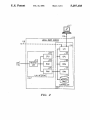
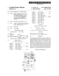
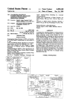
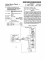
3 5,287,103 DETAILED DESCRIPTION FIG. 1 shows a simpli?ed block diagram illustrating a multi-LAN network 100 employing an exemplary em bodirnent of this invention. Multi-LAN network com prises LAN 110 and connections to a plurality of other 4 (such as New Jersey) and have a development center in a second state (such as Illinois). In both of these cases, it multi-LAN network 100 communicates using the IN is not possible to have a high quality metallic path con necting the router and the ?le server. Therefore, ?ber optics are employed in this embodiment of this inven tion, but other media may be used, facilities permitting. LAN 110 comprises, for purposes of this illustrative embodiment of this invention, a plurality of work sta TERNET protocol, as is known in the art and fully described in D. E. Comer, Intemetworking with tions 111 and a test system 112, as is common in many development laboratories. Work stations 111 comprise a LANs, such as 120 and 130. Nodes on each LAN on TCP/IP, Vol. 1: Principles, Protocols, and Architec ture, Second Edition, Prentice Hall, 1991. Nodes on LAN 110 communicate with each other using, for ex ample, ETHERNET (R) protocol, either version 1 or version 10 (ETHERNET is a registered trademark of the Xerox Corporation) as the physical layer protocol terminal or small personal computer as is known in the art. Test system 112 comprises a computer, switching frame or other device that is commonly stored program controlled. In this exemplary embodiment, test system 112 is down loaded with control software from ?le server 150, and controlled by one or more of work in the Open Systems Interconnection (0S1) 7-layer reference model established by the International Orga stations 111. In the prior art when a work station 111 or test sys tem 112 came onto the LAN, it could communicate nization for Standardization, Switzerland, and de scribed in W. Stallings, Data and Computer Communi 20 with work stations 111 and test system 112, but could not communicate with LANs 120 and 130, or with ?le cations, Third Edition, Macmillan Publishing Com‘ server 150, because it did not know its Internet ID. pany, 1991. LAN 120 uses, for purposes of this illustra Work stations 111 and test system 112 do not have tion, STARLAN10 as is known in the art and described storage facilities that are protected from power shut in AT&T Starlan Network, Hardware Technical Refer down, sometimes call “diskless systems.” In order to ence, Issue 01, Select Code: 999-120-201, available from obtain an Internet ID, work stations 111 and test system AT&T. LAN 130 may be, for example, another 112 must send a message to ?le server 150, containing an ETHERNET LAN. The intra-network protocols used address. File server 150 maintains an address table 116 here are for illustrative purposes only, as this invention with a translation of address to Internet ID. Since work may be used with any physical layer LAN protocol. stations 111 and test system 112 do not know the ad All of the LANs are connected to a router 140. dress of the ?le server, they must send broadcast mes Router 140 receives all messages on all of the LANs sages on the network requesting their Internet ID. connected to it and recognizes messages that are to be Routers such as router 140 are traditionally built so forwarded to another LAN. Router 140 translates the that messages are routed with maximum ef?ciency and message protocol from the source LAN to the destina a minimum of congestion. Since broadcast messages tion LAN, and transmits the message on the destination LAN. Routers such as router 140 are known in the art. cause congestion, routers such as router 140 do not pass In this exemplary embodiment, router 140 is manufac tured by‘ Proteon Inc., Two Technology Drive, West borough, Mass, and described in Proteon Model p4200 Hardware Installation Manual, No: 42-040182-00, De cember, 1989. Additionally, router 140 accepts mes on broadcast messages, because broadcast messages sages from all LANs destined for a common ?le server 150. File server 150 is usually a main frame or large mini have to be sent to all LANs as well as to ?le server 150. Therefore, all “diskless systems” on a LAN cannot 40 communicate from the home LAN 110 to another LAN or to the ?le server without going through the router to obtain an Internet ID from the ?le server, but the router will not forward broadcast messages. To solve this problem, a local RARP server 115 is computer, as is known in the art. File server 150 pro 45 used according to the principles of this invention. The local RARP server (LRS) listens to the network for vides mass storage and other resources for all of the broadcast messages of one or more speci?c types, trans LANs connected to router 140. File server 150 may also have print spooler and other functions that may be lates the address into an Internet ID, and responds to required by the LANs. Router 140 translates a message received for ?le server 150 into the proper protocol and sends the message to ?ber optic modern 160, in this the requester. In the preferred embodiment, local preferred embodiment. Fiber optic modern 160 trans includes, in the preferred embodiment, a terminal 117 for updating address table 116 and controlling such functions as monitoring packet transfer and diagnostics. mits the message via ?ber optic links 162 to a second ?ber optic modern 164. Second ?ber optic modem 164 communicates with ?le server 150. File server 150 re sponds to the request by sending a message back to the requester via ?ber optic modem 164, ?ber optic links RARP server 115 includes a copy of the address table 116 as kept in ?le server 150. Local RARP server 115 Additionally, an optional connection 118 may connect local RARP server 115 to router 140, and local RARP server 115 may control, initialize, etc. router 140. In this exemplary embodiment, when test system 112 is powered up or otherwise initialized, as part of the 162 and ?ber optic modem 160 to router 140. Router 140 translates the response to the proper protocol, and sends the message on the appropriate LAN. boot function it will send a broadcast message on LAN It is increasingly common to have a ?le server lo cated in a computer center or facility remote from the one or more of the LANs it serves. For example, a 110 requesting its Internet ID. Local RARP server 115 monitors LAN 110, receives the message and deter mines that the message is a broadcast message. Local research and development facility may have a complex RARP server 115 next uses the address of the device comprising several buildings. One or more of the build 65 from the broadcast message and performs a table look up to determine the Internet ID for the received ad ings may be physically located remotely from the com dress. Local RARP server 115 formats and sends a puter center where the ?le server is located. Also, it is message to the requester including the Internet ID. The increasingly common to have a ?le server in a ?rst state 5 5,287,103 requester, in this case, test system 112, may then com municate with ?le server 150 or LANs 120 and/or 130. FIG. 2 is a block diagram illustrating the main com ponents of Local RARP server 115. Local RARP server 115 is, in this exemplary embodiment, divided into a LAN interface 210 and a controller 250. LAN interface 210 provides the physical connection to LAN 110 and receives all messages sent on LAN 110 at re ceive unit 215. Receive unit 215 is under the control of CPU 220 and noti?es CPU 220 of any incoming mes sage packets of a speci?c type. In this preferred embodi ment, receive unit 215 noti?es CPU 220 of the receipt of messages of type RARP. CPU 220 is a dedicated LAN interface CPU, which is Intel 82586, available from the Intel Corp., Beaverton, Greg, and described in Local Area Networking (LAN) Component User’s Manual, Order Number: 230814-004, 6 tion. The local RARP server of this invention is initial ized upon power-up. Therefore, processing starts in balloon 300 with power-up. Processing continues to box 302 where the system boots via ROM 265 (FIG. 2) or alternatively pumped from a card download system as is known in the art. Processing continues to box 304 where the parameters for the LAN interface 210 (CPU 220 FIG. 2) are set and the receive unit 215 (FIG. 2) is started. Processing continues to a large loop that remains active until the power is turned off. Processing contin ues to decision diamond 306 which represents a power off. If the power goes off, processing terminates at bal loon 308. If the power is on, then processing continues to decision diamond 310 where a test is made if the receive unit has received a packet. If the receive unit has received a packet, then processing continues to the process packet subroutine (FIG. 4). When the process in the preferred embodiment. CPU 220 is a processor, packet subroutine returns, processing loops to the test under control of a program stored in ROM 230. CPU for power decision diamond 306. 220 causes message packets of type RARP to be moved If there were no packets in the receive unit memory from receive unit 215 into RAM 240. CPU 220 then in decision diamond 310, then processing continues to causes the message packets to be moved from RAM 240 box 312, where communication is established with the into controller 250. IO port 275 (FIG. 2). A determination is made in deci Controller 250 reads the header of the RARP mes sage, searching for the ?eld which contains the address 25 sion diamond 314 whether the serial port is active. If the serial port is not active, processing loops to decision of the device requesting its Internet ID. Controller 250 diamond 306. If, in decision diamond 314, the serial port is under control of CPU 260, which is a standard micro is active, then processing continues to the process serial processor in the preferred embodiment. CPU 260 is a port subroutine (FIG. 5). When the process serial port processor, under control of a program stored in ROM subroutine returns, processing loops back to decision 265. Message packets are received in controller 250 at diamond 306. ' RAM 270 after being transferred from RAM 240 of Turning now to FIG. 4, the process packet subrou LAN interface 210 via direct memory access, as is tine is shown. Processing starts in box 400 where the known in the art, under control of CPU 220. CPU 260 packet is moved from receive unit 215 (FIG. 2) to mem ?nds the address in RAM 270, and performs a data base 35 ory through LAN interface RAM 240 and into control look up in address table 116. ler RAM 270 (FIG. 2). The receive unit memory is then Address table 116, in the preferred embodiment, com freed. Processing continues to decision diamond 402 prises a 1.44 megabit “floppy” disk system, as is known where a test is made of the message type. If the message in the art. Alternatively, address table 116 may com type is not a RARP type, then the message is not a prise a large “hard" disk system, EEPROM, PROM, or some other form of occasionally writable, non-volatile 40 broadcast message requesting a reverse address transla tion. Processing thus continues to box 404 where the memory. Address table 116 may be updated by simply packet is discarded. Processing then continues to bal removing the disk and adding or deleting addresses, or loon 406 where the subroutine returns. may be updated by a program running on CPU 260, If in decision diamond 402 the message is of type which displays address-Internet ID pairs, and allows the user to add, change, and delete such pairs. Address 45 RARP, then processing continues to decision diamond 408 where a test is made if the address found in the table 116 may, for more sophisticated system, be up message is in the address table. In a normal case, the dated by requesting a new copy of the address table address will be found in the address table and the Inter from the ?le server. net ID is sent to the client in box 410. Processing then Upon determining the Internet ID, CPU 260 formats returns at balloon 406. a return message packet for the device requesting its If in decision diamond 408 the address was not in the Internet ID in RAM 270. CPU 260 then noti?es CPU address table, then processing continues to box 412 220, and CPU 220 causes the message packet to be where a diagnostic message is issued. The diagnostic moved into RAM 240 via direct memory access. CPU message is, in the preferred embodiment, a message sent 220 then causes the message packet to be moved into through the IO port 275 to the control terminal 117. receive unit 215, which send the message packet out on However, the diagnostic message may be sent to the LAN 110. address found in the message packet indicating a failure Controller 250 also comprises in the preferred em or a message may be sent via LAN 110 to ?le server bodiment an I/O controller 275, as is known in the art, 150, and the failure logged. Processing then proceeds to for coordinating serial I/O with devices other than LAN 110. In this embodiment, I/O port 119 in I/O 275 60 the return balloon 406. is connected to a terminal 117 for controlling controller 250. Additionally, one I/O port 118 of I/O 275 is op FIG. 5 shows the service serial port subroutine. Ser vice serial port subroutine is directed towards control of tionally connected to router 140, for remotely control ling router 140. Any of the I/O ports of I/O 275 may be ever, it would also be possible for the subroutine to a terminal such as terminal 117 (FIGS. 1 and 2). How connected to additional LANs, or other serial devices, 65 control the router or accept local area network input, as is known in the art. Processing starts at at box 500 as is known in the art. where the main menu is displayed on the screen. Pro FIG. 3 is a flow chart showing the control of CPU cessing continues to decision diamond 502 where a test 260 (FIG. 2) of the preferred embodiment of this inven 5,287,103 7 8 is made for serial input from a keyboard. If there is no copy of the address table may be requested from the ?le serial input from the keyboard, then processing returns server. If the Internet ID is still not found in the new copy of the address table, then the local RARP server could log the failed request to the ?le server. It is, there fore, intended that such variations be included within the scope of the claims. We claim: 1. A method for providing an intemetwork identi?ca in balloon 504. _ If in decision diamond 502 there is serial input from a keyboard, then processing continues to box 506 where an input line is retrieved from the keyboard. Processing continues to decision diamond 508 where a test is made if the input request is to update the address table. If the input is not to update the table, then processing pro tion to a client on a local area network (LAN), said 10 LAN client comprising a node on said LAN that does ceeds to connector A (FIG. 6). If in decision diamond 508 input request is to update the table, then processing continues to box 510 where receive unit 215 (FIG. 2) is disabled. The receive unit is disabled so that no partial Internet IDs are delivered to clients on the LAN, and so that the proper Internet ID is delivered in all cases. Processing continues to box 512 where the address table maintenance menu is displayed. Processing continues to box 514 where the operation request is obtained from the keyboard. Processing con tinues to decision diamond 516 where a test is made if the keyboard input is a request to exit. If it is not, then processing continues to box 518 where the address table 116 (FIG. 2) is updated with additions, changes, dele tions, or a display of the address table entries is per formed. Processing continues from box 518 back to box 512 where the address table maintenance menu is dis played. If in decision diamond 516 that the input from the keyboard was determined to be a request to exit, then processing continues to box 520 where address table 116 (FIG. 2) is updated. Processing then continues to box 522 where receive unit 215 (FIG. 2) is enabled so that Internet IDs may be obtained and processing returns in balloon 524. Turning now to FIG. 6, if in decision diamond 508 the input is determined not to be a request to update the address table, then processing proceeds through con nector A to box 526 where the normal mode menu is displayed. Processing continues to decision diamond 528 where input is retrieved from the keyboard and the 40 operation mode is selected. Processing may continue in box 530 where all packets coming into the receive unit not have a writable, non-volatile memory for storing said intemetwork identi?cation, said LAN being con nected to other LANs by a router, said router being con?gured to not pass broadcast messages from said LAN to said other LANs, said method comprising: receiving on said LAN a broadcast message from said LAN client during initialization of said LAN cli ent, said broadcast message requesting an intemet work identi?cation for use in subsequent communi cation with nodes on said other LANs and specify ing an address of said LAN client; translating said address of said LAN client into said intemetwork identi?cation; and transmitting a message on said LAN to said LAN client containing said intemetwork identi?cation, whereby said intemetwork identi?cation of said LAN client is obtained without said router passing said broadcast message to other LANs. 2. A method in accordance with claim 1 wherein said translating comprises performing a table look up in an address table where said LAN address is paired with its corresponding intemetwork identi?cation. 3. A method in accordance with claim 2 further com prising: if said LAN address is not paired with a correspond ing intemetwork identification in said address ta. ble, transmitting a diagnostic message to said LAN client. 4. A method in accordance with claim 2 further com prising: if said LAN address is not paired with a correspond ing intemetwork identi?cation in said address ta are monitored. This informs the maintenance person of ble, transmitting a request to a tile server for an the packet traf?c on local area network 110. Alterna update of said address table. tively, in box 532 a diagnostic packet may be sent across 45 5. An apparatus for use in a LAN, said LAN compris LAN 110 to determine the functionality of both the ing one or more clients that do not have writable, non LAN and the local RARP server. Also, in box 534, volatile memory for storing an intemetwork identi?ca communication may be established through I0 275 tion, said client relying on a node on one other LAN for data storage, said LAN being connected by a router to (FIG. 2) to router 140 (FIG. 1). After each step in this process, processing continues through connector A where packets are checked for RARP requests. This gets high priority to handling of packets, which is the primary functionality of the local RARP server. Pro cessing then returns back to box 526. Also, as a result of the select operation mode type decision diamond 528, a selection would be made to exit the normal mode in box 536. In this case, processing continues to the return balloon 524. It is to be understood that the above-described em bodiment is merely an illustrative principle of the inven tion and that many variations may be devised by those skilled in the art, without departing from the scope of the invention. For example, local RARP server could other LANs, including said one other LAN, said router being con?gured to not pass broadcast messages from said LAN to said other LANs, said apparatus providing an intemetwork identi?cation in response to a broadcast message request for intemetwork identi?cation at ini tialization of one of said client, said broadcast message including said one client's address, said apparatus com prising: means for receiving said broadcast message from said LAN; and means, coupled to said means for receiving, for pro viding a translation of said address of said one client to an intemetwork identi?cation responsive to determining that said received message is a be used to monitor for unauthorized access to a local broadcast message request for intemetwork identi ?cation. area network. Local RARP server could also be used as 65 a monitor for counting and reporting on unusual mes 6. An apparatus in accordance with claim 5 wherein sage types being distributed on LAN 110. Additionally, said translation means comprises ?rst means for deter if the Internet ID is not found in the address table, a new mining that said received message comprises a broad 5,287,103 wherein said updating means comprises means for sending an update request to a ?le server, and means responsive to a message from said ?le server responsive to said request by said ?rst means for provid ing said internetwork identi?cation. for updating said second means. 12. On a LAN, a terminal without storage of an internetwork identi 7. An apparatus in accordance with claim 6 wherein said second means comprises a disk system. 8. An apparatus in accordance with claim 6 wherein said second means comprises a writable, nonvolatile electronic device. 9. An apparatus in accordance with claim 6 further comprising means for interfacing said ?rst means to a terminal. 10 11. An apparatus in accordance with claim 10 cast message request for an internetwork identi?cation, and second means for receiving said address and pro viding said internetwork identi?cation, said ?rst means coupled to said second means and said second means ?cation necessary to permit communication to and from it outside said LAN; storing means on said LAN for storing said internet 15 10. An apparatus in accordance with claim 6 further comprising work identi?cation unique to said terminal; and translating means for monitoring broadcast messages on said LAN from said terminal and for responding to selected broadcast messages from said terminal by delivering a message to said terminal compris ing said internetwork identi?cation from said stor age means. means for updating said second means. a: 25 35 45 50 55 65 a a a a