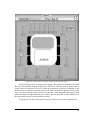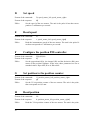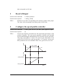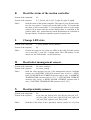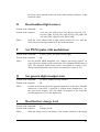
1
Koala
¨
USER MANUAL
Version 1.1
K-Team S.A.
Lausanne, 23 février 1999
Documentation author
K-Team S.A.
Ch. de Vuasset, CP 111
1028 Préverenges
Switzerland
email: [email protected]
WWW: http://www.k-team.com
Trademark Acknowledgements
IBM PC: International Business Machines Corp.
Macintosh: Apple Corp.
SUN Sparc-Station: SUN Microsystems Corp.
LabVIEW: National Instruments Corp.
Khepera: K-Team S.A.
NOTICE:
• The contents of this manual are subject to change without notice.
• All efforts have been made to ensure the accuracy of the contents of this manual. However, should any errors be detected. In this case, please inform the K-Team S.A.
• The above notwithstanding K-Team S.A. can assume no responsibility for any errors
in this manual.
TABLE OF CONTENT
Introduction . . . . . . . . . . . . . . . . . . . . . . . . . . . . . . . . . . . . . . . . . 1
How to Use this Manual . . . . . . . . . . . . . . . . . . . . . . . . . . 1
Safety Precautions . . . . . . . . . . . . . . . . . . . . . . . . . . . . . . . 2
Recycling . . . . . . . . . . . . . . . . . . . . . . . . . . . . . . . . . . . . . . 2
The Robot Parts . . . . . . . . . . . . . . . . . . . . . . . . . . . . . . . . . . . . . . 3
The Koala mobile robot . . . . . . . . . . . . . . . . . . . . . . . . . . . 3
Overview and part definition . . . . . . . . . . . . . . . . . . 3
ON - OFF battery switch . . . . . . . . . . . . . . . . . . . . . 7
Running mode selector, reset button and settings . . 7
The RS232 serial lines . . . . . . . . . . . . . . . . . . . . . . . 8
Motors and motor control . . . . . . . . . . . . . . . . . . . . . 8
Infra-red proximity sensors . . . . . . . . . . . . . . . . . . 10
Ambient light measurements . . . . . . . . . . . . 11
Reflected light measurements . . . . . . . . . . . . 13
Batteries . . . . . . . . . . . . . . . . . . . . . . . . . . . . . . . . . 14
General input and output ports . . . . . . . . . . . . . . . . 14
Cables and accessories . . . . . . . . . . . . . . . . . . . . . . . . . . . 15
Power supply accessory . . . . . . . . . . . . . . . . . . . . . . . . . . 15
Recharger accessory . . . . . . . . . . . . . . . . . . . . . . . . . . . . 16
Software support floppy disks . . . . . . . . . . . . . . . . . . . . . 17
Unpacking Test . . . . . . . . . . . . . . . . . . . . . . . . . . . . . . . . . . . . . 17
Connections . . . . . . . . . . . . . . . . . . . . . . . . . . . . . . . . . . . . . . . . 17
Configuration for robot-computer communication using
an external power supply . . . . . . . . . . . . . . . . . . . . . . . . . 17
Charging configuration . . . . . . . . . . . . . . . . . . . . . . . . . . 19
The serial communication protocol . . . . . . . . . . . . . . . . . . . . . . 20
The tools . . . . . . . . . . . . . . . . . . . . . . . . . . . . . . . . . . . . . 20
The control protocol . . . . . . . . . . . . . . . . . . . . . . . . . . . . . 21
Testing a simple interaction . . . . . . . . . . . . . . . . . . . . . . . 22
Using LabVIEW® . . . . . . . . . . . . . . . . . . . . . . . . . . . . . . . . . . . 24
Hardware configuration . . . . . . . . . . . . . . . . . . . . . . . . . . 24
Set up of the serial link . . . . . . . . . . . . . . . . . . . . . . . . . . 24
Motors . . . . . . . . . . . . . . . . . . . . . . . . . . . . . . . . . . . . . . . 25
Sensors . . . . . . . . . . . . . . . . . . . . . . . . . . . . . . . . . . . . . . . 28
Braitenberg's vehicle . . . . . . . . . . . . . . . . . . . . . . . . . . . . 30
Advanced programming . . . . . . . . . . . . . . . . . . . . . . . . . 31
Motors . . . . . . . . . . . . . . . . . . . . . . . . . . . . . . . . . . . 31
Sensors . . . . . . . . . . . . . . . . . . . . . . . . . . . . . . . . . . 32
Example of Braitenberg's vehicle . . . . . . . . . . . . . . 33
References . . . . . . . . . . . . . . . . . . . . . . . . . . . . . . . . . . . . . . . . . 35
Appendix A: Communication protocol to control the robot . . . 36
Appendix B: Connectors . . . . . . . . . . . . . . . . . . . . . . . . . . . . . . 43
Appendix C: How to open the robot and change the ROM . . . 47
Appendix D: Technical specifications . . . . . . . . . . . . . . . . . . . 49
Appendix E: Running modes . . . . . . . . . . . . . . . . . . . . . . . . . . 50
1
INTRODUCTION
First of all, thanks for choosing the Koala robot platform!
Koala is the continuation of the work of the K-Team started with the Khepera
miniature mobile robot. Khepera is worldwide known as a good and stable equipment for
basic research and education. Advantages of Khepera are the software and hardware
modularity, the software and hardware robustness and the simple use. The main disadvantage of Khepera is that it cannot be used for realistic tests and applications, mainly
due to its size. Koala brings the advantages of Khepera to a realistic size: multiprocessor,
BIOS software, simplicity to use, robustness and good price are scaled up to a bigger
robot. The Koala mobile robot is a Khepera compatible platform with added functionnalities, more computational power, better inter-processor communication and improved
expandibility.
To get the last information on K-Team products, look to http://www.k-team.com
1.1
How to Use this Manual
This manual is organised into 7 chapters and 5 appendix. To learn how to make the
best use of your Koala robot you are urged to read all of chapters 1 through 4. The chapter 5 presents the serial communication protocol that makes a remote control from a
workstation possible. You need to read the chapter 6 if you use the software LabVIEW®.
The appendix can be referred to as necessary.
Chapter 1
Gives an introduction to this manual and the Koala robot.
Chapter 2
explains the functionality of the Koala robot and their main
accessories.
Chapter 3
explains how to make the first test of the robot after unpacking.
Chapter 4
gives the standard Koala configurations.
Chapter 5
presents the serial communication protocol.
Chapter 6
is addressed to the users of LabVIEW®. It shows simple virtual instruments (VI) to control the robot functionality and a
little example of programming in this environment.
Appendix A details the commands of the serial communication protocol.
Appendix B details the connectors pinning.
Appendix C details how to change the ROM of the robot. This operation
has to be made only if really necessary!
Appendix D details the technical specifications of the basic Koala robot.
Appendix E details the different running modes.
1
1.2
Safety Precautions
Check all unit's operating voltage before operation.
It must be identical with that of your local power supply. The operating voltage is indicated on the nameplate of the power supply.
Don't plug or unplug any connector when the system is switched ON.
All connections (including extension addition or disconnection) must be made when the
robot and the interface are switched OFF. Otherwise damages can occur.
Switch OFF the robot if you will not use it for more than a day.
Switch the robot and any additional power supplies OFF if you do not work with the robot.
Do not open the robot if you do not have been explicitly allowed.
Open the robot only if you have been allowed by a specific documentation. Perform this
operation following carefully the instructions given in appendix C.
Do not manually force any mechanical movement.
Avoid to force, by any mechanical way, the movement of the wheels or any other part.
Avoid to push the robot in a way that forces the wheels.
If you have any questions or problems concerning the robot, please contact your Koala
dealer.
1.3
Recycling
Think about the end of life of your robot! Parts of the robot can be recycled and it
is important to do so. It is for instance important to keep Ni-Cd batteries out of the solid
waste stream. When you throw away a Ni-Cd battery, it eventually ends up in a landfill or
municipal incinerator. These batteries, which contain heavy metals, can contribute to the
toxicity levels of landfills or incinerator ash. By recycling the Ni-Cd batteries through
recycling programs, you can help to create a cleaner and safer environment for generations to come. For those reasons please take care to the recycling of your robot or robot
accessories at the end of its life cycle, for instance sending back the old equipment to the
manufacturer or to your local dealer.
Thanks for your contribution to a cleaner environment!
2
2
THE ROBOT PARTS
2.1
The Koala mobile robot
2.1.1
Overview and part definition
1
2
6
3
7
4
5
8
Figure 1: Side view and position of some parts of the robot.
Make an external inspection of the robot. Note the location of the following parts:
1. Controls and indicators
2. Cover
3. Infrared proximity sensors
4. Upper bodywork part
5. Front bodywork part
6. Motion block
7. Wheels
8. Wheel fixation
3
1
2
8
9
3
10
11
4
12
5
13
14
6
7
15
16
Figure 2: Back view and location of some parts.
1. Infrared proximity sensors
2. Upper bodywork part
3. Cover (can be removed easily)
4. Direct RS232 serial port
5. Reset button (has to be pressed inside the body)
6. Green TxD (transmit data) indication Light Emitting Diode “LED” (data
from the Koala robot to the host computer)
7. Red RxD (receive data) LED (data from host computer to the Koala robot)
8. Lateral (left) bodywork part
9. Green user reserved LED (number 0)
10. Green user reserved LED (number 1)
11. Red user reserved LED (used by process ALIVE, blinking, or user reserved number 2)
12. Running mode selector (0 to 15)
13. 10 A main power fuse (inside the robot)
14. Green power supply LED
15. Red empty battery LED
16. ON-OFF battery switch
4
1
7
8
2
9
3
10
4
11
5
12
6
13
14
Figure 3: Top view (cover and protection plate removed) with indication of some parts
1. Fixation points for the protection plate and the extension rack
2. DATA INPUT group of user I/O extensions
3. ANALOG INPUT group of user I/O extensions
4. Screws for the fixation of the upper bodywork part
5. Mechanical extension support plate
6. Khepera compatible serial extension bus
7. Parallel extension bus connector
8. Power connector for the extension rack
9. Jumper for selection of the active serial (RS232) line
10. ROM
11. BDM connector (only for factory use)
12. POWER OUTPUT group of user I/O extensions
13. DATA OUTPUT group of user I/O extensions
14. Koala Universal Interface Connector “UIC”
5
Viewpoint
1
10
2
3
11
12
4
5
13
6
14
7
15
16
8
17
9
18
Figure 4: Inside view (mechanical extension support plate removed) with indication of some parts
1. Fixation points for the upper bodywork part
2. POWER OUTPUT group of user I/O extensions
3. DATA OUTPUT group of user I/O extensions
4. Khepera compatible serial extension bus
5. Internal RS232 serial line (normally connected to the Koala “UIC”)
6. DATA INPUT group of user I/O extensions
7. ANALOG INPUT group of user I/O extensions
8. 1 A fuse of VCC (+5V) of connector 16 (internal, behind fuse 9)
9. 1 A fuse of +12V of connector 16
10. 1 A fuse of VCC (+5V) of group 3 (internal)
11. 1 A fuse of +12V of group 2 (internal)
12. Mechanical fixation points
13. 1 A fuse of VCC (+5V) of connectors 14 and 18
14. Power supply connector A
15. Power supply input connector (normally connected to the Koala “UIC”)
16. Power supply connector B
17. 1 A fuse of +12V of connectors 14 and 18
18. Power supply connector C
6
2.1.2
ON - OFF battery switch
It allows the user to switch the robot power ON or OFF.
When ON, the robot is powered. If the robot is connected to an external power supply, the power supply has also to be switched on before the robot. When OFF, the robot is
not powered.
2.1.3
Running mode selector, reset button and settings
The ROM installed on your robot has an important library of software modules for
the real time control of the Koala robot. Part of these modules (building the BIOS) ensure
the basic functionnalities of the Koala robot, like motor control, sensors scanning etc.
Another part of these modules ensure the interface with the user through the serial line.
Depending on your use of the robot (remote control, downloading, test, demo etc.) you
can select a specific module by setting the correspondent running mode.The “running
mode selector” (point 12 of figure 2) allows the selection of the most important running
modes in several configurations. You have the choice between the following configurations:
0. Demonstration mode: execution of a Braitenberg vehicle algorithm
(number 3 according to the “Vehicle” book [Braitenberg84]) for obstacle
avoidance.
1. Mode for the control of the robot by the serial communication protocol
using a serial link with a communication speed of 9600 Baud.
2. Same as mode 1 but with the communication speed of 19200 Baud.
3. Same as mode 1 but with the communication speed of 38400 Baud.
4. ROM user application mode: start an application stored into the ROM (if
any).
5. Downloading mode: in this mode the robot waits for a program to be
transferred from the host computer to the Koala robot (S format, 9600
Baud).
6. Same as mode 5 but with the serial link at 38400 Baud.
7. Test of the functionality of the robot. The result of successive tests is
given on the serial link (9600 Baud).
8. Same as mode 1 but using the MMA 0 as communication channel.
9. FLASH user application mode: start an application stored into the
FLASH memory (if any). To store a program in flash, look to the corresponding commands of the serial communication protocol (see “The
serial communication protocol” on page 20)
A-F. Reserved.
The serial link set-up is always 8 bit, 1 start bit, 2 stop bit, no parity. Only the baud
rate changes. The set-up of the jumpers can be changed at any time. If the robot is running it is necessary to reset it to make the set-up effective.
The reset button can be used at any time to reset the robot.
7
2.1.4
The RS232 serial lines
There are two main serial line connectors on the Koala robot: the external direct
RS232 serial line connector (item 4 of figure 2) and the internal RS232 serial line connector (item 5 of figure 4). To avoid conflicts, only one of these two connectors can be
active and be connected to the CPU. The choice of the connection is made using the
selection jumper showed in figure 3 under the point 9, following the rule illustrated in
figure 5.
Selection (active):
Forward robot
direction
Back
direct
connector
Internal
connector
Back direct RS232
serial line connector
Figure 5: Jumper position for the selection of the active RS232 serial connector.
Two LEDs (items 6 and 7 of figure 2) show the activity of the transmit and receive
RS232 serial channels of the Koala CPU. This activity will correspond to the activity of
the connector selected as indicated in figure 5. If the activity that you observe on these
lines do not correspond to the activity of your host computer (when you send data, the
red receive LED do not show any activity, for instance) then the problem could be at the
level of your computer, the cable or the jumper illustrated in figure 5.
The transmit LED (green, items 6 of figure 2) indicates the activity of the channel
transporting data from the Koala robot to the host PC. The receive LED (red, items 7 of
figure 2) indicates the activity of the channel transporting data from the host PC to the
Koala robot.
2.1.5
Motors and motor control
Every wheel is moved by a DC motor coupled with the wheel through a 84:1
reduction gear. An incremental encoder is placed on the motor axis and gives 100 pulses
per revolution of the motor. This allows a resolution of 8400 pulses per revolution of the
wheel that corresponds to 32.5 pulses per millimetre of forward displacement of the
robot.
The Koala main processor has the direct control on the motor power supply and
can read the pulses of the incremental encoder using a special unit called UPP (Universal
Pulse Processor). It can also read the current used by each motor, which are proportional
to the torque on the wheels.
The motor power supply can be adjusted by the main processor by switching it ON
and OFF at a given frequency and during a given time. The basic switching frequency is
constant and sufficiently high not to let the motor react to the single switching. By this
way, the motor react to the time average of the power supply, which can modified by
8
changing the period the motor is switched ON. This means that only the ratio between
ON and OFF periods is modified, as illustrated in figure 6. The PWM value is defined as
the time the motor is switched ON.
basic period
50µs
power
ON period
ON
OFF
time
power
power
basic period
basic period
ON
ON
95%
ON period
5%
ON period
OFF
OFF
time
time
Figure 6: The “pulse with modulation” (PWM) power supply mode is based on a ratio between the ON
time and the total time. The basic switching frequency is constant.
The PWM values can be set directly, or can be managed by a local motor controller. The motor controller can perform the control of the speed or position of the motor,
setting the correct PWM value according to the real speed read on the incremental encoders.
user control modes
target
position
control
speed
control
trajectory position
generator
+
position
error
+
position PID
controller
-
+
speed
error
+
speed PID
controller
dx/dt
PWM
control
automatic
switching
pulse
counter
motor
increments
PWM
PWM
generator
encoder
Figure 7: Structure of the motor controllers and levels of user access.
Both DC motors can be controlled by a PID controller executed in an interrupt rou-
9
tine of the main processor. Every term of this controller (Proportional, Integral, Derivative) is associated to a constant, setting the weight of the corresponding term: Kp for the
proportional, Ki for the integral, Kd for the derivative.
The motor controller can be used in two control modes: The speed and the position
modes. The active control mode is set according to the kind of command received. If the
controller receives a speed control command, it switches to the speed mode. If the controller receives a position control command, the control mode is automatically switched
to the position mode. Different control parameters (Kp, Ki and Kd) can be set for each of
the two control modes.
Used in speed mode, the controller has as input a speed value of the wheels, and
controls the motor to keep this wheel speed. The speed modification is made as quick as
possible, in an abrupt way. No limitation in acceleration is considered in this mode.
Used in position mode, the controller has as input a target position of the wheel, an
acceleration and a maximal speed. Using this values, the controller accelerates the wheel
until the maximal speed is reached, and decelerates in order to reach the target position.
This movement follows a trapezoidal speed profile, as described in figure 8.
speed
The input values and the control mode of this controller can be changed at every
moment. The controller will update and execute the new profile in the position mode, or
control the wheel speed following the new value in the speed mode. A status of the controller indicates the active control mode, the phase of the speed profile (on target or in
movement) and the position error of the controller.
max_speed
position
acc
-acc
time
target position
start position
time
Figure 8: Speed profile used to reach a target position with a fixed acceleration (acc) and a maximal speed
(max speed).
10
2.1.6
Infra-red proximity sensors
Sixteen sensors are placed around the robot and are positioned and numbered as
shown in figure 8.
L2
L1
L0
R0
R1
R2
R3
L3
L4
R4
L5
R5
R6
L6
L7
R7
Figure 9: Position of the 16 IR sensors.
These sensors embed an infra-red light emitter diode and a receiver. For more
information about these particular devices, please refer to the documentation of the sensor manufacturer. The exact type is TSL252 and the manufacturer is Texas Instruments.
This sensor device allows two measures:
• The normal ambient light. This measure is made using only the receiver
part of the device, without emitting light with the emitter. A new measurement is made every 20 ms. During the 20 ms, the sensors are read in a
sequential way every 2.5 ms. The value returned at a given time is the result
of the last measurement made.
• The light reflected by obstacles. This measure is made emitting light using
the emitter part of the device. The returned value is the difference between
the measurement made emitting light and the light measured without light
emission (ambient light). A new measurement is made every 20 ms. During
the 20 ms, the sensors are read in a sequential way every 2.5 ms. The value
returned at a given time is the result of the last measurement made.
The output of each measurement is an analogue value converted by a 10 bit A/D
converter. The following two sections (2.1.6.1 and 2.1.6.2) illustrate the meaning of this
10 bit values.
11
2.1.6.1
Ambient light measurements
The measurement of the ambient light versus the distance and angle of a light
source are illustrated in figure 10 and figure 11.
Measured value
1023
800
600
400
200
0
0
100
200
300
400
500
600
700
800
900
1000
Distance between robot and light source [mm]
Figure 10: Typical measurement of the ambient light versus the distance of a light source of 1,1 Watt.
Measured value
1023
900
800
700
600
500
400
300
200
100
0
-10 0
20
Sensor R0
Sensor R1
Sensor R2
Sensor R3
Sensor R4
Sensor R5
Sensor R6
Sensor R7
Sensor L7
Sensor L6
Sensor L5
Sensor L4
Sensor L3
Sensor L2
Sensor L1
Sensor L0
40
60
80 100 120 140 160 180 200 220 240 260 280 300 320 340 360
Angle ß (degrees)
ß
light source
R3
R2
R1
R0
L0
L1
L2
L3
R4
R5
R6
R7
L7
L4
L5
L6
Figure 11: Typical measurement of the ambient light with the robot turning in front of a light source. The
angle on the X axis is measured between the forward direction of the robot and the direction of the light.
12
The important difference between the various sensors is due to local differences of
the sensors themselves: The sensor orientation is not always radial, the distance to the
light source is not the same for all sensors and the local reflections due to the optics interact in a different way. This optical interaction is also the origin of the several double
maximum that can be observed on several sensors.
The dark correspond to a measured value of about 0. The saturation of the sensor
(too much light) correspond to a value of about 700.
All these measurements depend very strongly from various factors like the distance
of the light source, the colour, the intensity, the vertical position, etc. These two figures
show only the global shape of the sensor's response.
2.1.6.2
Reflected light measurements
The measurement of the proximity of obstacles by reflected light is not a distance
measurement. This kind of measure is based on the quantity of light the obstacle reflects
back to the robot. This measurement depends on two major factors: the reflexivity of the
obstacle (colour, kind of surface...) and the ambient light. Figure 12 shows some measurements giving an idea of the response of the sensor facing obstacle of different material
and colours. The difference is very important and this type of response has to be taken in
account by the controller.
Measured value
1050
White plastic
Wood
800
Red plastic
Grey sponge
600
Black plastic
Grey paper
400
200
0
0
25
50
75
100
125
150
175
200
225
250
Distance to the wall [mm]
Figure 12: Measurements of the light reflected by various kinds of objects versus the distance to the
object.
The dependence of the measurement from the ambient light is not illustrated here
but can be explained in the following way: The light receiver has a different sensibility in
different light conditions. If there is a basic important ambient light, the receiver is more
sensible that if it works in the dark. For this reason, an obstacle detected in the light will
13
return a bigger value than if the same object is detected in the dark. Also this difference
can be important and has to be taken in account by the controller.
The directionality of the sensor measurement is illustrated in figure 13: these sensors have a field of view of about ± 10 degrees.
Measured value
1023
800
600
ß
Obstacle
50mm
L0
400
200
0
-20
-10
0
10
20
Angle ß (degrees)
Figure 13: Typical response of a proximity sensor in front of an obstacle (20 mm in width) viewed under a
variable angle.
The characteristics of the different physical sensors can change in a large range.
The measurements made on six sensors of the same robot placed in near-to-identical
conditions can be different for several reasons. Small differences of sensors conditions
(horizontal orientation of the sensor, particular device sensibility due to differences in the
manufacturing process, difference in distance due to the fact that the robot has not a pure
cylindrical shape) can bring important differences. This aspect is well illustrated by
figure 11, where the robot turns on place and the different sensors, placed in similar conditions, react in a different way.
2.1.7
Batteries
The robot can be equipped with a pack composed by 10 rechargeable Nickel - Cadmium batteries with a capacity spanning from 1.4 to 2.4 Ah. This capacity allows the
robot an autonomy of about 2-4 hours in the basic configuration and running the braitenberg obstacle avoidance algorithm. The battery can be removed and recharged externally.
Each battery has an internal memory that can be accessed by the Koala main CPU
or by the battery recharger, if able to perform this action. In this internal memory are stored several characteristics of the battery, like the type, the total capacity and the charge
level. When the robot works using the battery, the power consumption is measured and
the charge level stored in the internal battery memory is updated. By this way, if the
recharger updates correctly the battery, it is possible to know the exact charge at every
moment, inside or outside the robot. If the battery recharger is not able to perform this
action, a manual update of the battery charge can be made.
14
2.1.8
General input and output ports
The Koala robot has a set of free input and output lines available to the user (items
2,3,12 and 13 in figure 3). Four main groups can be found:
• Analog input lines. Input voltage have to be in the range GNA-Vref which
should be 0-4.096V
• Digital CMOS input lines
• Digital CMOS output lines low current (<20mA, 0-5V). A GND and VCC
outputs are available in this group.
• Digital open collector output lines high current (<250mA, 0-12V). A battery voltage output and a power ground are available in this group.
Figure 14 shows the position of these four main groups, specifying all single lines.
Analog inputs
Vref
Reference voltage 4.096V
ANA5 Analog channel 5
......
ANA0 Analog channel 0
GNA Analog ground
DIN11 Digital input 11
.......................
DIN0
Digital input 0
Digital Inputs
Digital CMOS outputs
VCC
+5V (2 outputs)
DCO3 CMOS output channel 3
...
DCO0 CMOS output channel 0
GND Digital ground (2 outputs)
BATT
DPO7
+12V battery voltage (2 outputs)
Digital power output channel 7
..............
DPO0
GND
Digital power output channel 0
Power ground (2 outputs)
Digital open collector outputs
Figure 14: Position and description of the general input and output channels
2.2
Cables and accessories
The basic Koala configuration do not has any cables. Cables for external power
supply are supplied with the external power supply. Cables for recharge are supplied with
the battery recharger.
Some extra parts are also included in the package: screws and jumpers.
15
2.3
Power supply accessory
An external box can provide the power supply to the Koala. The power supply is
connected to the universal interface connector (item 14 of figure 3). The power coming
from this connector goes to the robot by the battery pack (see figure 15) which has to be
replaced by a DC/DC converter.
Universal
Interface
Connector
DC/DC
converter
Battery
external power supply
Power destination
Power source
Power transformation
Figure 15: Power route using a battery (left) or an external power supply (right). In the case of an external
power supply, a DC/DC converter replaces the battery pack.
The connection between the power supply and the Koala robot is made by the
general interface cable and rotating cable provided with the power supply.
The power supply box has a RS232 connector which is linked to the Koala robot
internal RS232 connector. To use it, please be careful about the RS232 configuration
jumper (see “The RS232 serial lines” on page 8).
SAFETY PRECAUTION: The power supply must be connected to the wall
socket and switched ON only when all other connections are already made.
2.4
Recharger accessory
To be recharged, the battery pack has to be removed from the Koala.
The general interface connector placed on the battery pack can be used to recharge
it. Different types of rechargers are available:
• Standard rechargers: these rechargers can recharge the battery included in
the pack, but do not access to the internal memory and do not update the
data stored inside the battery pack. This operation has to be performed
manually, if necessary.
• Intelligent rechargers: this type can access to the internal memory, can
recognise automatically the type of accumulator, the capacity and the
charge level. They also update the internal memory state and let you use the
full possibilities of the intelligent power management of the Koala.
16
2.5
Software support floppy disks
Three 3,5˝ floppy disks contain all the modules for interfacing the Koala robot with
LabVIEW® in it version 4.1 on PC, Macintosh® and SUN® (see “Using LabVIEW®” on
page 24). The software LabVIEW® is a product of National Instruments and is not included in the package.
3
UNPACKING TEST
After unpacking it is important to test the functionality of the robot. A test that
uses most of the possible functionnalities is available with the running mode 0: a Braitenberg vehicle (see “Running mode selector, reset button and settings” on page 7). To
obtain this running mode operate as following:
• Put the robot on a flat surface without danger for the robot. Water or steps
on the ground have to be considered as dangerous for the robot. Be aware
that the robot will move rather quickly and, avoiding obstacles, will avoid
your hand approaching to switch it OFF....
• Verify to be in running mode 0 (setting for the running mode 0, see “Running mode selector, reset button and settings” on page 7).
• Switch the robot ON and put the robot on the ground.
The robot must start to go forward while avoiding obstacles. The obstacles must be
bright to better reflect the light of the proximity sensors. If the robot does not operate
properly, check the three points mentioned above, recharge the robot and retry. If the
robot does not correctly avoid the obstacles, please contact your Koala dealer.
4
CONNECTIONS
There are two widely used standard configurations: a first one used to charge the
robot battery and a second one that allows the communication between the robot and the
host computer when the robot is connected to an external power supply.
4.1 Configuration for robot-computer communication using an external power supply
This configuration allows the communication between the robot and a host computer through a serial link. On the host computer side the link is made by a RS232 line.
The following connections must be made (see figure 16):
• Between the robot and the power supply box by the universal interface
cable delivered with the power supply box. This cable also supports the
17
RS232 serial line of the robot.
• Between the power supply box and the host computer by a standard RS232
cable. This cable is not in the package because there are several standards
at the level of the host connector. You can easily find this cable by your host
computer dealer.
• Set the running mode selector according to the desired running mode (see
“Running mode selector, reset button and settings” on page 7). Be careful
that in running mode 0 the robot starts moving when powered.
• Plug the power supply to the wall socket.
To test the connection and the settings of the serial port do the following manipulation:
• Put the robot on a flat surface on which the robot can move around easily.
The battery switch must be OFF.
• Place the running mode selector in the position 1 (setting for the running
mode 1, see “Running mode selector, reset button and settings” on page 7).
• Run a terminal emulator on your host computer (for instance VT100) connected to the serial port on which you have connected the robot. Configure
your terminal as following: 9600 Baud, 8 bit, 1 start bit, 2 stop bit, no
parity.
• Plug the mural power supply to the main, switch it ON, then switch the
robot ON.
Universal
Interface
Link
RS232
Figure 16: Configuration for the communication between the robot and the host computer using an external power supply.
18
Your terminal should display:
ROM of minirobot KOALA,...
The transmit data (Robot TxD on the power supply box) green lamp should blink
after reset. If the robot does not respond as indicated, check the points mentioned above
and retry. If unable to operate the serial transfer, please contact your dealer.
4.2
Charging configuration
Warning: It is necessary to discharge the batteries before recharging. Avoid to
start a recharging process on charged batteries. This can cause damages.
To charge the battery of the robot, the following connections have to be made:
• Between the battery pack and the charger module with the universal interface cable.
Charger
Battery
Universal Interface Link
Figure 17: Connections to recharge the robot’s batteries.
• Between the interface/charger module and the power supply with the jack.
• Plug the power supply to the wall socket only when these connections are
established.
If the charger allows different charging modes, select the right one. Prefer a slower
“discharge and charge” to a simple “charge” which can, in long term, damage the battery.
If a selection is required, consider that the battery pack includes 10 cells.
19
5
THE SERIAL COMMUNICATION PROTOCOL
The serial communication protocol allows the complete control of the set-up and of
the functionnalities of the robot through an RS232 serial line. It correspond to running
modes 1 to 3 (see “Running mode selector, reset button and settings” on page 7). The
connection configuration necessary to use these functionnalities is presented in the section 4.1 of this manual. The set-up (baudrate as well as data, start, stop and parity bits) of
the serial line of your host computer must correspond to the one set on the robot with the
jumpers (running modes 1 to 3, always 8 bit, 1 start bit, 2 stop bit, no parity).
The communication between the host computer and the Koala robot is made sending and receiving ASCII messages. Every interaction is composed by:
• A command, sent by the host computer to the Koala robot and followed by
a carriage return or a line feed.
• When needed, a response, sent by the Koala to the host computer.
In all communications the host computer plays the role of master and the Koala the
role of slave. All communications are initiated by the master.
The communication is based on two types of interactions: one type of interaction
for the set-up of the robot (for instance to set the running modes, the transmission baudrate...), and one type of interaction for the control of the functionality of the robot (for
instance to set the speed of the motors, to get the values of the sensors...). The interactions allowing the set-up of the robot are based on commands called tools. The interactions for the control of the robot functionality uses protocol commands and responses.
5.1
The tools
Here is the description of some basic tools:
“run”
Start a function stored in the ROM. It has to be followed by
the function name. The functions available in the ROM can
be listed with the list tool and have a identification string
beginning with “FU”. Some of the functions correspond to
the running modes presented in the section 2.1.3. Using the
run tool it is possible, for instance, to start the demo mode
(Braitenberg vehicle, corresponding to the running mode 0,
as described in section 2.1.3) typing “run demo” and return.
“serial”
Set the serial channel to a baud-rate, given as parameter. For
instance, typing “serial 19200” and return sets the baudrate
to 19200 Baud.
“help”
Show the help message of the modules available in the ROM.
A parameter can be used to indicate a need of help on a particular item. “help list” gives an help message for the list tool.
“help demo” gives an help message on the demo function
mentioned above.
“list”
Give the list of all the tools, functions, protocol commands
20
“k-team”
“net”
“memory”
“restart”
“process”
“sfill”
“flash”
5.2
and other modules available in ROM. For every item listed
you get an ID, a name, a description and a version. The ID is
composed by four letters. The first two letters define the
family of the module: IDs starting by “TA” define tasks running on Koala, “FU” functions that can be executed with the
run command, “PR” protocol commands, “TO” tools like
this one and “BI” BIOS components.
Give a short description of the K-Team active members.
Give an information about the extensions installed on the
robot. For each item listed you get a name, an ID (to be used
to address the turret), a description and a revision.
Give an information about the memory used by the system.
Reset the robot. This action is the same as a hardware reset.
Give the list of all processes running on Koala in parallel to
the serial communication protocol management.
Start a Motorola S format downloader. This downloader do
not start the execution of the code at the end of the download.
To download and execute a code, please use the sloader function, started by the command “run sloader”.
Gives access to some action taken on the flash memory.
“flash E” erases the flash. “flash W” copy the RAM to the
flash. The sequence “flash E”, “sfill” followed by a download
and “flash W” make your program to be stored in the flash.
To execute it, just type “run user-flash” or select running
mode 9.
The control protocol
To control the functionnalities of the Koala robot (motors, sensors etc.), a set of
command are implemented in the control protocol. Also in this case, the communication
with the Koala robot is made sending and receiving ASCII messages. Every interaction
between host computer and Koala is composed by:
• A command, beginning with one or two ASCII capital letters and followed,
if necessary, by numerical or literal parameters separated by a comma and
terminated by a carriage return or a line feed, sent by the host computer to
the Koala robot.
• A response, beginning with the same one or two ASCII letters of the command but in lower-case and followed, if necessary, by numerical or literal
parameters separated by a comma and terminated by a carriage return and a
line feed, sent by the Koala to the host computer.
In all communication the host computer plays the role of master and the Koala the
role of slave. All communications are initiated by the master. The protocol commands are
17 and a complete description is given in Appendix A.
21
5.3
Testing a simple interaction
To better understand both tools and protocol commands, we propose to do a very simple
test as following:
• Set the connection configuration presented in section 4.2.
• Start on your host computer a terminal emulator (for instance VT100) with
the serial line set to 9600 Baud, 8 bit data, 1 start bit, 2 stop bit, no parity.
We start testing some protocol commands:
• Type the capital letter B followed by a carriage return or a line feed.
• The robot must respond with b followed by an indication of the version of
software running on the robot and terminated by a line feed.
• Type the capital letter N followed by a carriage return or a line feed.
• The robot must respond with n followed by 8 numbers separated by a
comma and terminated by a line feed. These numbers are the values of the
proximity sensors presents on the robots.
• Retry the same command (N) putting some obstacles on the front of the
robot. The response must change.
• Type the protocol command D,5,-5 followed by a carriage return or a line
feed.
• The robot must start turning on place and respond with d and a line feed.
• To stop the robot type the protocol command D,0,0 followed by a carriage
return or a line feed.
• Type the protocol command H followed by a carriage return or a line feed.
• The robot must respond with h followed by 2 numbers separated by a
comma and terminated by a line feed. These numbers are the values of the
position counters of each wheel.
• Type the protocol command G,0,0 followed by a carriage return or a line
feed.
• This command set the position counters to the 2 values given as parameters. The answer is composed by a g and a line feed.
• Retry the protocol command H to verify that the G command has been executed.
• Type the protocol command C,1000,1000 followed by a carriage return or
a line feed.
• The robot respond with d and goes forward 80 mm.
• Retry the protocol command H to verify the final position.
• Try other commands following the description given in Appendix A.
We start testing some tools:
• Type the command help followed by a carriage return or a line feed.
• The robot must respond with the list of all tools available.
22
•
•
•
•
•
•
Type the command help serial followed by a carriage return or a line feed.
The robot must respond with the description of the “serial” tool.
Type the command help D followed by a carriage return or a line feed.
The robot must respond with the description of the “D” protocol command.
Type the command list followed by a carriage return or a line feed.
The robot must respond with the list of all code modules present in the
EPROM. In addition to the “tools” (characterised by a “TOXX” ID) and
the “protocol” commands (characterised by a “PRXX” ID) you can find on
the list “functions” (characterised by a “FUXX” ID) and BIOS modules
(characterised by a “BIXX” ID). On every module you can have an help
message.
23
6
USING LABVIEW®
The goal of this chapter is to familiarise you with the LabVIEW environment in the
context of Koala use. To this end, the examples are presented in an increasing order of
complexity, our advice is to follow the chronological order of presentation. Please refer
to the LabVIEW manuals for more general information about this software.
LabVIEW runs on your PC, Macintosh® or SUN®, and controls the functionality
of the Koala robot using the serial communication protocol described in chapter 5.
6.1
Hardware configuration
Set your environment as explained in section 4.1. The running mode selector must
be set to obtain the running mode 2.
6.2
Set up of the serial link
To enable the exchange of information between your computer and the robot, you have
to set up the serial link. Be sure that the connection cable is connected at both ends, that
the robot is powered, then start LabVIEW and open the Set-up virtual instrument (called
also VI) present in your floppy disk. The following panel appears:
Figure 18: Set up panel for serial link initialisation.
24
Now, select the serial port on which the robot is connected. This selection must be
made for every module that you will use. Then click once on the run arrow at the top of
the window. That's all! The serial link with Koala is set to 19200 baud. It will remain so
until you quit LabVIEW.
6.3
Motors
We will now control the displacement of the robot. Be sure that the serial link has
been correctly installed, then open the Motors VI present on the floppy disk. Now your
screen displays the following panel:
Figure 19: Motors panel: 2 sliders controlling the speed of each wheel.
Before to move the robot, you must learn how to stop it. Different means are
available. Starting from the most efficient:
• Press the reset button on the robot once.
• Put the value 0 for each speed using the sliders. Don't forget that these new
values will only be taken into account at the next execution (i.e., click on
the arrow).
• Click on the button labelled Stop. You have also to click on the arrow again
25
so that the robot takes your last decision into account. Before trying to give
another values to the motors, click again on the button (to de-select this
option). This last option is the best way to stop the robot.
You control directly each one of the motors by simply putting the desired speed
values. There are two ways of actions:
• Move the cursors,
• Write directly the desired values in the digital display.
Possible values are constrained between -10 and +10 so to take care of the mechanics. To transmit your order to the robot, just click once on the arrow. Change the values
and click again. You see that the robot continues moving at the same speed until new
values are send. If you are getting bored with clicking on the arrow, try one click on the
double arrow. Click on the stop icon to stop the execution.
The robot has two incremental encoders on the wheels. Using these sensors it is
possible to measure the displacement and the speed of each wheel at every moment. The
VI “Get_position” ask for the content of the increment counter, which represent the displacement of the wheel. The unit of displacement correspond to 0.03 mm.
Figure 20: Get_position panel: 2 indicators show the position of each wheel.
To test the functionality of this module just click on the double arrow to start the
recurrent running mode. At this moment the VI will show you the actual position of each
wheel. To change the position of the wheel use the “Motors” VI as described above, and
observe the result on the “Get_position” VI. To set the position counter to a given value
you can use the “Set_position” VI.
The “Get_speed” VI display the speed of each wheel. This value is computed on
the robot, based on the information of the position and the time.
26
Figure 21: Get_speed panel: 2 indicators show the speed of each wheel.
To test the functionality of this module just click on the double arrow to start the
recurrent running mode. At this moment the VI will show you the actual speed of each
motor. To change the speed of the motors use the “Motors” VI as described above. You
can also try to set the motor speed to 15 using the “Motors” VI, then slow down the
wheels with your fingers and look to the result on the “Get_speed” VI.
It is also possible to give to the robot a position to reach, expressed using the position of the two wheels and the speed profile to reach these positions (as described in section 2.1.5 of this manual). The target position can be given to the robot with the
“Control_position” VI:
Figure 22: Control_position panel: 2 sliders controlling the position to reach for every wheel.
27
This VI is associated with the “Conf_pos_param” VI, which set all the parameters
of the speed profile:
Figure 23: Conf_pos_param panel: all the parameters of the speed profile can be controlled.
To test the position control, please start setting to 0 the two position counters of the
two wheels, using the “Set_position” VI or resetting the robot. At this moment you can
try the “Control_position” VI setting a distance of 1000 on both sliders and running the
VI once, clicking on the run arrow. Test other movements keeping both left and right displacements identical.
To start other kinds of trajectory, bring back the robot to the 0 position or use the
“Set_position” VI to reset the counter. Then use the “Conf_pos_param” VI to set the left
maximal speed to 10, the left acceleration to 32, and keeping the values of the right trajectory to the default value indicated in figure 24. Run the VI once to make these values
effective. Then set, on the “Control_position” VI, the goal position of the left wheel to
1000 and the goal position of the right wheel to 2000. Run the VI once and observe the
trajectory of the robot.
6.4
Sensors
In its basic version, Koala has 16 infra-red sensors. You will now easily understand
their characteristics. Be sure of the set-up of the serial link, then open the Sensors VI that
you have on the floppy disk. Now your screen displays the following panel:
28
Figure 24: Sensors panel: 16 gauges displaying the infra red values.
Each proximity sensor is displayed as a gauge. The gauges are placed on the panel
like the corresponding sensors on the robot. The exact value received is written underneath. Values are between 0 and 1023. Start the acquisition as before by clicking on the
double arrow (to stop the execution, click on the stop icon that will appear). Now you are
free to test the response of the sensors. In particular, some materials reflect better than
others the infra-red light emitted by the sensors. You are also able to state difference in
the individual response of the proximity sensors.
The graph on the left of the panel shows the values for each sensor against time.
29
6.5
Braitenberg's vehicle
At this stage, you have a good understanding of motors and sensors functionality.
In the next step we will combine these two modules. Let's open both panels (Motors and
Sensors), but do not start them. This way, you will be able to watch, at the same time,
data issued from the sensors and those send to the motors. Open the instrument called
Braitenberg3c. Now your screen displays also the following panel:
Figure 25: Braitenberg’s vehicle panel: 3 sliders defining the sensibility thresholds.
Each of these three sliders defines the sensibility to the obstacles of a given group
of sensors:
• “Front” corresponds to the central front sensors,
• “45 degrees” corresponds to the lateral front sensors,
• “90 degrees” corresponds to the sensors on the side of the robot.
Start the application by clicking on the arrow. It is not necessary to click on the
double arrow in the present case. The sensibility can be modified by moving the cursors
or writing directly the desired values. Koala now moves, avoiding bumping into obstacles. Test different sensibilities on its behaviour. This control structure is inspired from
the work of V. Braitenberg [Braitenberg84].
Note that this VI uses the “Motors” and “Sensors” modules as sub-VIs. One of the
30
advantages of LabVIEW is to allow a context-free use of the building modules. This fact
is particularly interesting for debugging.
The button labelled “stop” stops the robot and the execution of the VI. It is a much
better way than using the stop icon (above rubber), because the stop button stops the
robot before stopping the VI.
6.6
Advanced programming
Now that we have executed different manipulations using LabVIEW and Koala, it
becomes interesting to present how it has been programmed. First, it is important to be
able to manipulate LabVIEW and its rolling menus. It is important that you locate the
“Show diagram” command in the “Windows” menu.
6.6.1
Motors
Select the Motors panel and open the diagram using the option ‘Show diagram’ of
the menu Windows. Your screen now displays the following schema:
Figure 26: Motors diagram corresponding to the Motors panel.
Each element of the panel used for displaying or getting data corresponds to an
icon. So, the box I32 under ‘Speed motor right’ is the getting variable of the corresponding slider on the front panel (of type 32 bits Integer). The same is true for the icon TF,
labelled Stop on the left, which is a boolean variable (type True False). This variable
allows to stop the motors by sending to each one a null speed value. The triangle represents an indirection controlled by the boolean variable “Stop”: If “Stop” is true, then the
output value (on the right) will be 0, if “Stop” is false, then the output value is the Speed
variable. These values are formatted by the next two icons to a string of ASCII characters. The character D is placed at the beginning of the string. Then, successively, the two
31
speed values are added and the string is terminated by a carriage return (\n). This string is
send to the robot using the serial link.
To control the speed of the wheels from another VI, the “Motors” VI can be used as
sub-VI. This use is demonstrated with the Braitenberg3c VI. The help window (figure
29) displays positions and semantics associated to the icon.
Figure 27: Semantic of the Motors connector.
6.6.2
Sensors
Select the Sensors panel and open the diagram using the option Show diagram of
the menu Windows. Your screen now displays the following schema:
Figure 28: Sensors diagram of the Sensors panel.
32
On the contrary to the “Motors” panel which sends values, this panel receives
values from the serial link. 16 values are extracted in 8 steps from the string. These
values are put into the variables (type Integer 32 bits) corresponding to the panel gauges.
These 16 values are transmitted to others modules through the icon used as a connector. This use is demonstrated with the experiment on Braitenberg's vehicle. The help
window (figure 29) displays positions and semantics associated to the icon.
Figure 29: Semantic of the Sensors connector.
6.6.3
Example of Braitenberg's vehicle
Select the Braitenberg panel and open the diagram using the option Show diagram
of the menu Windows. Your screen now displays the schema illustrated in figure 30.
This schema may appear complex at first glance. But, as we will see, it takes back
elements already studied. It can be decomposed into two parts: serial link initialisation
and avoiding behaviour. LabVIEW is a data-flow controlled language, so the execution
order of non-dependent control structures is not fixed. Serial link initialisation and avoidance behaviour are independent; but initialisation must occur first. The sequential structure allows the definition of an execution order, so initialisation is the first element of the
sequence. The second element contains the while loop where the avoidance behaviour is
executed until the boolean variable Stop becomes True (note the presence of a logical
inversion). This boolean variable is also transmitted to the “Motors” VI through its icon.
Its action will be to stop both motors. In the same way, the two speeds computed here are
sent to the “Motors” VI to be sent through the serial link to Koala.
33
Figure 30: Braitenberg’s vehicle diagram of Braitenberg’s vehicle panel.
Sensors values are received from the “Sensors” icon. They are normalised (/1000)
and multiplied by the corresponding sensibility value (type real Single). Front corresponds to the six central sensors (numbers 0, 1 and 2), 45 degree corresponds to the two
oblique sensors (number 3) and 90 degree corresponds to the two side sensors (numbers
4 and 5). The result is added to the value given by the spped input. The sum of the left
sensors corresponds to motor right. The sum of the right sensors corresponds to motor
left. These two values are then send to the motors. The computation needed is simple and
fast enough to control Koala in real-time without big delays. However, displaying
“Motors” and “Sensors” panels is a computational expensive operation. If you want
Koala to move faster, close these panels but don't close the Braitenberg panel!
34
7
REFERENCES
[Braitenberg84] Braitenberg V., “Vehicles: Experiments in synthetic psychology,” MIT
Press, 1984.
[Mondada93b] Mondada F., Franzi E. and Ienne P., “Mobile robot miniaturisation: a tool
for investigation in control algorithms.”, ISER3, Kyoto, Japan, 1993.
[National92] National Instruments, LabVIEW manuals, 1992-1996.
[K-Team94] Khepera User Manual 4.0, K-Team manuals, Lausanne, 1994.
35
APPENDIX A
COMMUNICATION PROTOCOL
TO CONTROL THE ROBOT
This communication protocol allows the complete control of the functionality of
the robot trough a RS232 serial line. The connection configuration needed is presented in
section 4.2. The set-up of the serial line of your host computer must correspond to the
one set on the robot with the jumpers (running modes 1 to 3). The protocol is constituted
by commands and responses, all in standard ASCII codes. A command goes from the
host computer to the robot: it is constituted by a capital letter followed, if necessary, by
numerical or literal parameters separated by a comma and terminated by a line feed. The
response goes from the robot to the host computer: it is constituted by the same letter of
the command but in lower case, followed, if necessary, by numerical or literal parameters
separated by a comma and terminated by a line feed.
To better understand this protocol we propose to do a very simple test as following:
• Set the jumpers of the robot for the running mode number 1 (See Figure 4).
• Set the connection configuration presented in section 4.2.
• Start on your host computer a terminal emulator (for instance VT100) with
the serial line set to 9600 Baud, 8 bit data, 1 start bit, 2 stop bit, no parity.
• Type the capital letter B followed by a carriage return or a line feed.
• The robot must respond with b followed by an indication of the version of
software running on the robot and terminated by a line feed.
• Type the capital letter N followed by a carriage return or a line feed.
• The robot must respond with n followed by 8 numbers separated by a
comma and terminated by a line feed. These numbers are the values of the
proximity sensors presents on the robots.
• Retry the same command (N) putting some obstacles on the front of the
robot. The response must change.
• Try other commands:
36
List of Available Commands
(∏ indicates CR (carriage return) or LF (line feed). ¶ indicates CR and LF.)
A
Configure PID speed controller
Format of the command:
A, Kp, Ki, Kd∏
Format of the response:
a¶
Effect:
B
Set the proportional (Kp), integral (Ki) and derivative (Kd) parameters of
the speed controller. At the reset, these parameters are set to standard
values: Kp to 1000, Ki to 800, Kd to 100.
Read software version
Format of the command:
B∏
Format of the response:
b, version_of_BIOS, version_of_protocol¶
Effect:
C
Give the version of the software present in the EPROM of the robot.
Set a position to be reached
Format of the command:
C,pos_left,pos_right∏
Format of the response:
c¶
Effect:
Indicate to the wheel position controller an absolute position to be reached. The motion control perform the movement using the three control
phases of a trapezoidal speed shape: an acceleration, a constant speed and
a deceleration period. These phases are performed according to the parameters selected for the trapezoidal speed controller (command J). The
maximum distance that can be given by this command is (2**23)-2 pulses
that correspond to 258m. The unit is the pulse that corresponds to
0.03mm. The movement is done immediately after the command is sent.
In the case another command is under execution (speed or position control) the last command replaces the precedent one. Any replacement transition follows acceleration and maximal speed constraints.
37
D
Set speed
Format of the command:
D, speed_motor_left, speed_motor_right∏
Format of the response:
d¶
Effect:
E
Set the speed of the two motors. The unit is the pulse/10 ms that corresponds to 3 millimetres per second.
Read speed
Format of the command:
E∏
Format of the response:
e, speed_motor_left, speed_motor_right¶
Effect:
F
Read the instantaneous speed of the two motors. The unit is the pulse/10
ms that corresponds to 3 millimetres per second.
Configure the position PID controller
Format of the command:
F,Kp,Ki,Kd∏
Format of the response:
f¶
Effect:
G
Set the proportional (Kp), the integral (Ki) and the derivative (Kd) parameters of the position regulator. At the reset, these parameters are set to
standard values: Kp to 400, Ki to 4, Kd to 400.
Set position to the position counter
Format of the command:
G, position_motor_left, position_motor_right∏
Format of the response:
g¶
Effect:
H
Set the 32 bit position counter of the two motors. The unit is the pulse,
that corresponds to 0,03 mm.
Read position
Format of the command:
H∏
Format of the response:
h, position_motor_left, position_motor_right¶
Effect:
38
Read the 32 bit position counter of the two motors. The unit is the pulse,
that corresponds to 0,03 mm.
I
Read A/D input
Format of the command:
I, channel_number∏
Format of the response:
i, analog_value¶
Effect:
J
Read the 10 bit value corresponding to the channel_number analog input.
The value 1024 corresponds to an analog value of 4,09 Volts.
Configure the speed profile controller
Format of the command:
J, max_speed_left, acc_left, max_speed_right, acc_right∏
Format of the response:
j¶
speed
Set the speed and the acceleration for the trapezoidal speed shape of the
position controller. The max_speed parameter indicates the maximal
speed reached during the displacement. The unit for the speed is the pulse/
10ms that corresponds to 3 mm/s. The unit for the acceleration is the
((pulse/256)/10 ms)/10 ms, that correspond to 1.172 mm/s2. At the reset,
these parameters are set to standard values: max_speed to 20, acc to 64.
max_speed
acc
position
Effect:
-acc
time
end position
start position
time
39
K
Read the status of the motion controller
Format of the command:
K∏
Format of the response:
k, T_left, M_left, E_left, T_right, M_right, E_right¶
Effect:
L
Read the status of the motion controller. The status is given by three numbers for every motor: T (target), M (mode) and E (error). T=0 means that
the robot is still on movement. T=1 means that the robot is on the target
position. M=0 means that the current displacement is controlled in the
position mode. M=1 means that the current displacement is controlled in
the speed mode. E indicates controller position or speed error.
Change LED state
Format of the command:
L, LED_number, action_number∏
Format of the response:
l¶
Effect:
M
Perform an action on one of the two LEDs of the robot. Possible actions
are: 0: turn OFF, 1: turn ON, 2: change status. The LED number 0 is the
lateral one, the LED number 1 is the frontal one.
Read robot management sensors
Format of the command:
M, sensor_number∏
Format of the response:
m, sensor_value¶
Effect:
N
Read the value measured on one of the management sensors. Available
sensors are: 0:BATTERY VOLTAGE (measure unit: 20 mV). 1: GENERAL CONSUMPTION CURRENT (measure unit: 8 mA). 2: AMBIENT
TEMPERATURE (measure unit: 0.1° C). 3: LEFT MOTOR CURRENT
(measure unit: 4 mA). 4: RIGHT MOTOR CURRENT (measure unit: 4
mA). 5: BATTERY TEMPERATURE (measure unit: 0.1° C).
Read proximity sensors
Format of the command:
N∏
Format of the response:
n,val_sens_left_90°,val_sens_left_45°,val_sens_left_10°,
val_sens_right_10°,val_sens_right_45°,val_sens_right_90°
,val_sens_back_right,val_sens_back_left¶
Effect:
40
Read the 10 bit values of the 8 proximity sensors (section 2.1.6.2), from
the front sensor situated at the left of the robot, turning clockwise to the
back-left sensor.
O
Read ambient light sensors
Format of the command:
O∏
Format of the response:
o,val_sens_left_90°,val_sens_left_45°,val_sens_left_10°,
val_sens_right_10°,val_sens_right_45°,val_sens_right_90°
,val_sens_back_right,val_sens_back_left¶
Effect:
P
Read the 10 bit values of the 8 light sensors (section 2.1.6.1), from the
front left sensor turning clockwise to the back-left sensor.
Set PWM (pulse with modulation)
Format of the command:
P, pwm_motor_left, pwm_motor_right∏
Format of the response:
p¶
Effect:
Q
Set the desired PWM amplitude (see “Motors and motor control” on
page 8 for more details) on the two motors. The minimum PWM ratio is 0
(0%). The maximal forward ratio (100%) correspond to a value of 255.
The maximal backwards ratio (100%) correspond to a value of -255.
Set general digital output state
Format of the command:
Q, output_number, action_number∏
Format of the response:
q¶
Effect:
S
Perform an action on one of the general output lines of the robot. Possible
actions are: 0: turn OFF, 1: turn ON, 2: change status. Outputs 0 to 7 are
the open drain outputs. The ON status correspond to the transistor
closed.Outputs 8 to 11 are the digital ones.
Read battery charge level
Format of the command:
S∏
Format of the response:
s,charge_level¶
Effect:
Read the charge level of the battery. The number returned is the charge
41
expressed in mAh.
Y
Read general digital input state
Format of the command:
Y, input_number∏
Format of the response:
y, input_value¶
Effect:
T
Read the status of the general input lines.
Send a message to an additional module
Format of the command:
T, module_ID, command∏
Format of the response:
t, response¶
Effect:
R
Send a command and return the response of the additional module with
module_ID. This module should be connected to the Khepera compatible
serial extension bus. The command parameter takes the same form as a
standard command, including an identification capital letter followed, if
necessary, by numerical parameters separated by a comma and terminated
by a line feed. The response takes the same format, starting with the same
letter but in lower case, followed, if necessary, by numerical parameters
separated by a comma and terminated by a line feed. The command and
response format are specific for every module.
Read a byte on the extension bus
Format of the command:
R, relative_address∏
Format of the response:
r, data¶
Effect:
W
Read the data byte available at the relative_address (0...63) of the extension bus.
Write a byte on the extension bus
Format of the command:
W, data, relative_address∏
Format of the response:
w¶
Effect:
42
Write the data byte at the relative_address (0...63) of the extension bus.
APPENDIX B
CONNECTORS
Female connector
Power supply 10-20V
Power supply 10-20V
Power supply ground
Power supply ground
Battery +
Battery VCC (+5V)
GND (0V)
Analog GND
1
2
3
4
5
6
7
8
9
10 Power sense +
19 Configuration pin 0
11 Power sense -
20 Configuration pin 1
12 Battery temperature
13 /SS
21 Configuration pin 2
22 Configuration pin 3
14 SCK
23 Rx Receive data RS232
15 MISO
24 Tx Transmit data RS232
16 MOSI
25 User reserved line
17 PAI
26 User reserved line
18 F7
Figure 31: Universal Interface Connector pinout.
1-2
3-4
5-6
7-8
GND
VCC
VBat
GNP
Logic power supply ground
Logic power supply +5V
Batter power supply +
Battery power supply -
Figure 32: Power supply general connector pinout
43
DB25 female connector
1 NC
14 NC
2 RxD
15 NC
3 TxD
16 NC
4 NC
17 NC
5 CTS
18 NC
6 DSR
19 NC
7 GND
20 NC
8 DCD
21 NC
9 NC
22 NC
10 NC
23 NC
11 NC
24 NC
12 NC
25 NC
13 NC
Not connected
Not connected
Receive data (data from PC to Koala)
Not connected
Transmit data (data from Koala to PC)
Not connected
Not connected
Not connected
Clear To Send (from Koala to PC)
Not connected
Data Set Ready (from Koala to PC)
Not connected
Ground
Not connected
Data Carrier Detect (from Koala to PC)
Not connected
Not connected
Not connected
Not connected
Not connected
Not connected
Not connected
Not connected
Not connected
Not connected
Figure 33: Direct external RS232 (DCE) connector pinout.
44
DB25 male connector
1 NC
14 NC
2 TxD
15 NC
3 RxD
16 NC
4 RTS
17 NC
5 CTS
18 NC
6 DSR
19 NC
7 GND
20 DTR
8 DCD
21 NC
9 NC
22 NC
10 NC
23 NC
11 NC
24 NC
12 NC
25 NC
13 NC
Not connected
Not connected
Transmit data (data from Koala to internal device)
Not connected
Receive data (data from internal device to Koala)
Not connected
Request To Send (from Koala to internal device)
Not connected
Clear To Send (from internal device to Koala)
Not connected
Data Set Ready (from internal device to Koala)
Not connected
Ground
Data Terminal Ready (from Koala to internal device)
Data Carrier Detect (from internal device to Koala)
Not connected
Not connected
Not connected
Not connected
Not connected
Not connected
Not connected
Not connected
Not connected
Not connected
Figure 34: Internal RS232 (DTE) connector pinout.
45
Female connector
1 GND Power supply ground
2 SCK
3 MISO
4 MOSI
5 /SPCOM
6 PAI
7 F7
8 VCC Power supply +5V
Figure 35: Khepera bus compatible connector pinout.
46
APPENDIX C
HOW TO OPEN THE ROBOT
AND CHANGE THE ROM
Changing the ROM of Koala needs very fine operations. The complete sequence of
actions is described in this appendix. Please follow very carefully these instructions. A
wrong action can cause mechanical damages to your robot. We do assume no responsibility for your wrong manipulations.
The ROM is situated on the main CPU board of the robot. To change it please:
• Disconnect the robot from the power supply, switch the robot OFF.
• Open the robot by removing the CPU cover and the protection plate. Be
very careful in this operation and be sure to be statically discharged.
• To extract the EPROM operate carefully. There are two access holes that
make the extraction possible as indicated in figure 36.
Figure 36: Location of the access holes for the extraction of the ROM.
• Use a specific extraction tool to push out the EPROM, very carefully, and
in a parallel way as indicated in figure 37.
GOOD
DAMAGE
BAD
Figure 37: Correct and wrong ROM extraction operation. On the left, the ROM extraction tool.
47
• Finally plug the new EPROM. Be careful about the orientation, given by a
corner of the ROM, as showed in figure 38.
Figure 38: One corner of the chip define its orientation.
• Place protection plate and cover again.
48
APPENDIX D
Processor
RAM
Flash
ROM
Motion
Sensors
Power
Autonomy
Extension busses
User free I/O
Size
Weight
TECHNICAL SPECIFICATIONS
Motorola 68331@16MHz
1 Mbyte
256Kbyte
128Kbyte
DC Motors with incremental encoder (about 25 pulses
per mm of avancement of the robot)
16 Infra-Red proximity and light sensors
Battery and ambient temperature
Motors torque and global power consumption
Rechargeable NiCd Battery with charge level memory.
The battery pack can be easily removed and replaced.
3 hours (Basic configuration with 2.4 Ah battery)
The robot can be expanded by modules added on the KExtension rack. Khepera turrets (with local processor)
and PC104 modules are also supported.
A special support is available on the front part of the
robot for mechanical extensions.
12 digital inputs [5...12V]
4 CMOS / TTL digital outputs
8 power (open collector) digital outputs [12V 250mA/
output]
6 analog inputs (10 bits A/D converter, 4.096V of dynamic)
Length: 32 cm, Width: 32 cm, Height: 20 cm
about 3 Kg
49
APPENDIX E
RUNNING MODES
F 0 1
2
3 4 56
BCDE
White line
7 8 9A
Figure 39: Running mode selector: the white line indicates the active mode. When changed, the active
mode becomes available only after a reset of the robot.
Running modes (see “Running mode selector, reset button and settings” on page 7):
0. Demonstration mode: execution of a Braitenberg vehicle algorithm
(number 3 according to the “Vehicle” book [Braitenberg84]) for obstacle
avoidance.
1. Mode for the control of the robot by the serial communication protocol
using a serial link with a communication speed of 9600 Baud.
2. Same as mode 1 but with the communication speed of 19200 Baud.
3. Same as mode 1 but with the communication speed of 38400 Baud.
4. ROM user application mode: start an application stored into the ROM
(if any).
5. Downloading mode: in this mode the robot waits for a program to be
transferred from the host computer to the Koala robot (S format, 9600
Baud).
6. Same as mode 5 but with the serial link at 38400 Baud.
7. Test of the functionality of the robot. The result of successive tests is
given on the serial link (9600 Baud).
8. Same as mode 1 but using the MMA 0 as communication channel.
9. FLASH user application mode: start an application stored into the
FLASH memory (if any). To store a program in flash, look to the corresponding commands of the serial communication protocol (see “The
serial communication protocol” on page 20)
A-F. Reserved.
The serial link set-up is always 8 bit, 1 start bit, 2 stop bit, no parity. Only the baud rate
changes. The set-up of the jumpers can be changed at any time. If the robot is running
it is necessary to reset it to make the set-up effective.
50