1
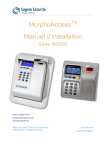
MorphoAccess® VP Series
Installation Guide
Copyright© 2011 Morpho
Osny, France
MorphoAccess® VP Series - Installation Guide
SSE-0000083011-01
July 2011
MorphoAccess® VP Series - Installation Guide
Warning
Warning
Copyright© 2011 Morpho. All rights reserved.
Information in this document is subject to change without notice and do not
represent a commitment on the part of Morpho. No part of this document may be
reproduced or transmitted in any form or by any means, electronic or mechanical,
including photocopying or recording, for any purpose without the express written
permission of Morpho.
This legend is applicable to all pages of this document.
This manual makes reference to names and products that are trademarks of their
respective owners.
2
MORPHO DOCUMENT – REPRODUCTION AND DISCLOSURE FORBIDDEN
SSE-0000083011-01
July 2011
MorphoAccess® VP Series - Installation Guide
Revision History
Revision History
The table below contains the history of changes made to the present document.
Version
01
SSE-0000083011-01
July 2011
Date
July 2011
Description
Document Creation
MORPHO DOCUMENT – REPRODUCTION AND DISCLOSURE FORBIDDEN
3
MorphoAccess® VP Series - Installation Guide
Table of Content
Table of Content
Section 1:
Introduction ............................................................................................................ 7
MorphoAccess® VP Terminal .................................................................................................... 8
Scope of the document.............................................................................................................. 9
Safety Instructions ................................................................................................................... 10
Recommendations for terminal implementation.................................................................... 12
Section 2: General Description .............................................................................................. 14
Box opening ............................................................................................................................. 15
Components of the initial package ......................................................................................... 16
Terminal's front view description ............................................................................................ 17
Terminal’s rear view description ............................................................................................. 18
MorphoAccess® VP Series Technical Characteristics .............................................................. 19
Section 3: Installation Procedure .......................................................................................... 21
Before proceeding to the installation: .................................................................................... 22
Installation directly on a wall .................................................................................................. 23
Installation on a standard electric box (Example of European electric box)........................... 28
Installation on a standard electric box (example of NON-European electric boxes) ............. 31
Installation without electric box (Direct to the wall) .............................................................. 33
Section 4: Electrical Interface ................................................................................................ 36
Wiring overview ...................................................................................................................... 37
Output Relay ........................................................................................................................... 39
Tamper Switch......................................................................................................................... 41
Power Supply ........................................................................................................................... 42
Wiegand output wiring ........................................................................................................... 43
Serial port cabling for DataClock and RS485 protocols .......................................................... 46
Ethernet wiring........................................................................................................................ 47
Section 5: User Interface ....................................................................................................... 49
Modes for controlling access rights ........................................................................................ 50
Configuring the terminal ......................................................................................................... 52
Anti-tamper and anti-pulling switches.................................................................................... 53
Section 6: Accessories, Software Licenses and PC Applications............................................ 54
Compatible Accessories, Licenses and Software ..................................................................... 55
Compatible PC applications .................................................................................................... 56
Section 7: Recommendations ................................................................................................ 57
Most useful areas for biometric data...................................................................................... 61
Position of finger ..................................................................................................................... 62
4
MORPHO DOCUMENT – REPRODUCTION AND DISCLOSURE FORBIDDEN
SSE-0000083011-01
July 2011
MorphoAccess® VP Series - Installation Guide
Table of Content
Condition of the finger ............................................................................................................ 64
How to get the latest versions of documents ......................................................................... 66
Documents concerning the MorphoAccess® terminal ............................................................ 67
Troubleshooting ...................................................................................................................... 70
Contacts .................................................................................................................................. 71
SSE-0000083011-01
July 2011
MORPHO DOCUMENT – REPRODUCTION AND DISCLOSURE FORBIDDEN
5
MorphoAccess® VP Series - Installation Guide
Table of Figures
Table of Figures
Figure 1: Implementation Recommendations .............................................................................12
Figure 2: Box Opening..................................................................................................................15
Figure 3: Box Content ..................................................................................................................16
Figure 4: MorphoAccess® VP Series terminal front views...........................................................17
Figure 5: MorphoAccess® VP Series terminal rear view ..............................................................18
Figure 6: Removing the top cover ...............................................................................................22
Figure 7: Drilling template ...........................................................................................................24
Figure 8: Wall plate fixing ............................................................................................................25
Figure 9: Terminal’s Body fixation ...............................................................................................25
Figure 10: USB Mass Storage Key plug ........................................................................................26
Figure 11: Assembling top and bottom covers ............................................................................26
Figure 12: Assembling protection accessory ...............................................................................27
Figure 13: MorphoAccess® VP with protection accessory ..........................................................27
Figure 14: Wall plate fixation.......................................................................................................29
Figure 15: Sample of Electric boxes .............................................................................................32
Figure 16: Fixing holes for mounting spacer ...............................................................................33
Figure 17: Sealing joint on wall plate / spacer.............................................................................34
Figure 18: Anti-pulling switches ..................................................................................................35
Figure 19: Cabling layout .............................................................................................................37
Figure 20: Internal relay block .....................................................................................................39
Figure 21: Example of electric latch connection .........................................................................40
Figure 22: Tamper switch block ...................................................................................................41
Figure 23: Power supply block .....................................................................................................42
Figure 24: Serial port Block – Wiegand protocol .........................................................................43
Figure 25: Serial port terminal, DataClock and RS485 protocols ................................................46
Figure 26: Ethernet Block ............................................................................................................47
Figure 27: RJ45 wiring ..................................................................................................................48
Figure 28: Most useful areas for biometric data .........................................................................61
Figure 29: Recommended finger positions..................................................................................62
Figure 30: Incorrect finger positions ...........................................................................................63
6
MORPHO DOCUMENT – REPRODUCTION AND DISCLOSURE FORBIDDEN
SSE-0000083011-01
July 2011
MorphoAccess® VP Series - Installation Guide
Section 1: Introduction
Section 1: Introduction
SSE-0000083011-01
July 2011
MORPHO DOCUMENT – REPRODUCTION AND DISCLOSURE FORBIDDEN
7
MorphoAccess® VP Series - Installation Guide
Section 1: Introduction
MorphoAccess® VP Terminal
Congratulations for selecting the MorphoAccess® VP Series, first ever Physical Access
Control terminals to integrate the state of the art multimodal technology combining
finger vein and fingerprint biometrics.
These terminals bring to access control systems the strong assets of the finger
vein/fingerprint multimodality:
the capability to address those individuals who usually experience difficulties to use
mono-modal biometric devices,
an excellent FRR@FAR ratio, which allows a high security level without affecting
comfort of use,
an enhanced resistance to spoofing (by combining the protection mechanisms
intrinsic to each technology and also by making the most of the new characteristics
resulting from the fusion of the two biometrics),
while offering the same easiness of use which makes finger biometrics-based systems
quickly adopted by end-users.
In addition, the MorphoAccess® VP Series have been designed with in mind two key
concepts:
attractiveness (choice of texture, quality of finishing…),
practicality at installation and connection, as illustrated by this installation guide.
We definitely believe that our MorphoAccess® VP Series will come up to the
expectations of our faithful and most demanding partners, as the ultimate solution for
Security, Accuracy and Performance of their equipments!
To ensure the most effective use of your MorphoAccess® VP Series terminal, we
recommend that you read this Installation Guide completely and attentively.
8
MORPHO DOCUMENT – REPRODUCTION AND DISCLOSURE FORBIDDEN
SSE-0000083011-01
July 2011
MorphoAccess® VP Series - Installation Guide
Section 1: Introduction
Scope of the document
This guide deals with the installation of MorphoAccess® VP Series, which is made up of
following list of products:
Products
MorphoAccess®
VP Series
SSE-0000083011-01
July 2011
Multimodal
finger vein/ fingerprint
biometrics
MorphoAccess®
VP-Bio
X
MorphoAccess®
VP-Dual
X
MIFARE®/DESFire®
Contactless smartcard
reader
MORPHO DOCUMENT – REPRODUCTION AND DISCLOSURE FORBIDDEN
X
9
MorphoAccess® VP Series - Installation Guide
Section 1: Introduction
Safety Instructions
The installation of this product should be made by a qualified service Person and
should comply with all local regulations.
It is strongly recommended to use a class II power supply at 12V [9V-16V] and 1A. min
in conformity with Safety Electrical Low Voltage (SELV). The 12V power supply cable
length should not exceed 10 meters.
This product is intended to be installed with a power supply complying with EN60950,
in accordance with the NEC Class 2 requirements; or supplied by a listed EN60950
external Power Unit marked Class 2, Limited Power source, or LPS and rated 12VDC,
1A minimum.
In case of building-to-building connection it is recommended to connect 0V to ground.
Ground cable must be connected with the terminal block 0V GND.
Note that all connections of the MorphoAccess® VP Series terminal described
hereafter are of SELV (Safety Electrical Low Voltage) type.
Wiring Recommendations
Morpho recommends to use a gauge AWG18 for 12V power supply when POE supply
is not use.
For information, this table shows the maximum weakening voltage observed on the
terminal MorphoAccess® VP:
Gauge AWG
Diameter
(mm)
Maximum
weakening @
1m
Maximum
weakening @
5m
Maximum
weakening @
10m
18
1.02362
0.021 V
0.105 V
0.209 V
20
0.8128
0.033 V
0.166 V
0.333 V
25
0.45466
0.106 V
0.531 V
1.062 V
28
0.32004
0.213 V
1.064 V
2.129 V
V2
V1
L
Weakening = loss of power due to wire resistance and its length
V2 = V1 – Weakening
10
MORPHO DOCUMENT – REPRODUCTION AND DISCLOSURE FORBIDDEN
SSE-0000083011-01
July 2011
MorphoAccess® VP Series - Installation Guide
Section 1: Introduction
Europe information
Morpho hereby declares that the MorphoAccess® VP Series terminal has been tested
and found compliant with following listed standards: EN302 291-2 V.1.1.1 (2005-07) +
recommendation 1999/519/CE with standard EN 50364; EN 301 489-3 V.1.4.1 (02),
and low voltage Directive 2006/95/CE: CEI60950-1:2005 2nd edition.
USA information
This device complies with part 15 of the FCC Rules. Operation is subject to
the following two conditions: (1) this device may not cause harmful
interference, and (2) this device must accept any interference received,
including interference that may cause undesired operation.
Changes or modifications not expressly approved by the party responsible for
compliance could void the user's authority to operate the equipment.
Responsible Party:
Morpho,
Le Ponant de Paris
27, rue Leblanc
F 75512 PARIS CEDEX 15
FRANCE
NOTE: This equipment has been tested and found to comply with the limits for a Class B
digital device, pursuant to Part 15 of the FCC Rules. These limits are designed to
provide reasonable protection against harmful interference in a residential
installation. This equipment generates uses and can radiate radio frequency energy
and, if not installed and used in accordance with the instructions, may cause
harmful interference to radio communications. However, there is no guarantee that
interference will not occur in a particular installation. If this equipment does cause
harmful interference to radio or television reception, which can be determined by
turning the equipment off and on, the user is encouraged to try to correct the
interference by one of the following measures:
Reorient or relocate the receiving antenna.
Increase the separation between the equipment and receiver.
Connect the equipment into an outlet on a circuit different from that to which the
receiver is connected.
Consult the dealer or an experienced radio/TV technician for help.
Shielded cables must be used with this unit to ensure compliance with category B FCC
restrictions.
SSE-0000083011-01
July 2011
MORPHO DOCUMENT – REPRODUCTION AND DISCLOSURE FORBIDDEN
11
MorphoAccess® VP Series - Installation Guide
Section 1: Introduction
Recommendations for terminal implementation
To secure properly an access, Morpho recommends installing the MorphoAccess® VP
terminal as a part of the typical Access Control environment, described in the figure
below.
Figure 1: Implementation Recommendations
This environment comprises:
-
The MorphoAccess® VP terminal itself
Its role is to perform one-to-many multimodal biometric identification or one-to-one
multimodal biometric verification, i.e. to identify the individual who is presenting his
finger on the terminal sensor by comparing his multimodal biometric data with the
references previously stored in the terminal database (in the form of multimodal
biometric templates) or to verify his identity using the reference stored in a
contactless card presented to the terminal.
12
MORPHO DOCUMENT – REPRODUCTION AND DISCLOSURE FORBIDDEN
SSE-0000083011-01
July 2011
MorphoAccess® VP Series - Installation Guide
Section 1: Introduction
-
An Access Controller (3rd party product)
The Controller is the element which controls the access rights of the individuals to the
secured area. For that reason, it must be located in the secured area.
The individuals who are authorized to access the secured area have their User ID listed
in a so-called "White List" (in contrast with a black list).
The MorphoAccess® VP terminal and the Controller are communicating according to
one of the TCP/IP, Wiegand, Dataclock or RS485 protocols:
The MorphoAccess® VP terminal sends User ID to the Controller
The Controller sends its decision to the MorphoAccess® VP terminal (which displays
GREEN light if access is granted or RED light if denied)
The MorphoAccess® VP terminal sends an alarm signal to the Controller as soon as a
malicious operation (terminal pulled out from the wall or having its bottom cover
opened out of maintenance operations) is detected; refer the paragraph dealing
with anti-pulling and anti-tamper switches for more explanations.
The Controller is part of the global Access Control System of the secured area, which
for instance can administrate the White List of the Controller and receive diaries of the
decisions taken by the Controller.
-
An Alarm (3rd party product)
This element is connected to the MorphoAccess® VP terminal through a dry contact.
The MorphoAccess® VP terminal sends the command to activate the Alarm as soon as
a malicious operation (terminal pulled out from the wall or having its bottom cover
opened out of maintenance operations) is detected; refer the paragraph dealing with
anti-pulling and anti-tamper switches for more explanations.
-
A Door Electric Latch or equivalent (3rd party product)
This element once activated opens the access. The Controller is the one which sends
the command to activate the latch if access is granted (i.e. if the individual's User ID is
listed in the Controller White List). Connection between these two elements is done
through a dry contact.
SSE-0000083011-01
July 2011
MORPHO DOCUMENT – REPRODUCTION AND DISCLOSURE FORBIDDEN
13
MorphoAccess® VP Series - Installation Guide
Section 2: General Description
Section 2: General Description
14
MORPHO DOCUMENT – REPRODUCTION AND DISCLOSURE FORBIDDEN
SSE-0000083011-01
July 2011
MorphoAccess® VP Series - Installation Guide
Section 2: General Description
Box opening
At the box opening, components shall be extracted from the white protection casing
as depicted in the pictures below.
Extract the bottom cover and the wall plate (which are not screwed to the terminal)
and keep them separate until the installation of the terminal is completed. The
screwing of the bottom cover is the last stage of the installation.
Not to forget to withdraw the sachet of screws, bolts and connectors from the white
protection casing.
The protection accessory provided is optional: it is recommended in the event of
installation in a strong parasitic luminosity area.
Figure 2: Box Opening
SSE-0000083011-01
July 2011
MORPHO DOCUMENT – REPRODUCTION AND DISCLOSURE FORBIDDEN
15
MorphoAccess® VP Series - Installation Guide
Section 2: General Description
Components of the initial package
2
4
5
6
3
1
8
7
Figure 3: Box Content
1. One (1) terminal’s body
2. One (1) top cover fixed at the body of the terminal
3. One (1) bottom cover
4. Two (2) block connectors (6 and 10 pins) for terminal's joint blocks
5. Four (4) M3X10 Screws (for terminal fixing to the wall plate) – T10 Torx and 4mm
flat print
6. Four (4) K25x8 Screws (Bottom cover fixing) – T8 Torx Print
7. One (1) protection accessory (which usage is optional)
8. One (1) wall plate
16
MORPHO DOCUMENT – REPRODUCTION AND DISCLOSURE FORBIDDEN
SSE-0000083011-01
July 2011
MorphoAccess® VP Series - Installation Guide
Section 2: General Description
Terminal's front view description
2
3
4
1
5
6
7
8
6
Figure 4: MorphoAccess® VP Series terminal front views
1. Terminal's body
2. Top cover
3. Contactless card reader
4. Multimodal biometric sensor (optical)
5. Bottom cover
6. Anti-tamper switches
7. USB port (for configuration and settings with a USB mass storage key, or for
installation of a Wi-Fi™ USB dongle)
8. Reset button
SSE-0000083011-01
July 2011
MORPHO DOCUMENT – REPRODUCTION AND DISCLOSURE FORBIDDEN
17
MorphoAccess® VP Series - Installation Guide
Section 2: General Description
Terminal’s rear view description
1
1
2
4
4
3
2
1
1
Figure 5: MorphoAccess® VP Series terminal rear view
1. Mounting holes (4)
2. Anti-pulling switches (2)
3. RJ45 (Power Over Ethernet)
4. Terminal blocks (2)
18
MORPHO DOCUMENT – REPRODUCTION AND DISCLOSURE FORBIDDEN
SSE-0000083011-01
July 2011
MorphoAccess® VP Series - Installation Guide
Section 2: General Description
MorphoAccess® VP Series Technical Characteristics
Item
Access control modes
Description
Identification (search for multimodal biometric data in a local
database)
Authentication with contactless card, with or without multimodal
biometric data check (only if terminal equipped with a smartcard
reader)
Multi-factor: identification or authentication (only if equipped
with a smartcard reader)
Proxy: the access control check is fully driven by a remote system
Man Machine Interface
Multi color LED
Multi tone Buzzer
Biometrics
MorphoSmart™ FINGER VP Biometric module inside for
multimodal biometric comparison.
With 500dpi, 256 gray levels optical sensor, PIV IQS certified by
the FBI
False Acceptance Rate (FAR) adjustable from 10-2 down to 10-8
Database capacity: 5,000 users (standard) or 10 000 users (with
specific license).
Log capacity
8,000 records (one per access request)
LAN/WLAN connection
For terminal configuration and data transfer:
Ethernet 10/100 Base T
Or Wi-Fi™ Wireless LAN (option), WEP and WPA encryption
available
Either TCP or SSL protocol
RFID cards (MorphoAccess® MIFARE® 4k
VP Dual only)
DESFire® 2k, 4k, 8k
Output serial port
The serial port supports WIEGAND, DATACLOCK ISO2, and RS485
protocols
Output relay switches
Access granted: 1 switch (either "open" or "close" in default state)
USB host port
Front port for terminal configuration through a USB mass storage
key or for Wi-Fi™ USB dongle.
Input signals
LED1/LED2 to activate the access granted relay
SSE-0000083011-01
July 2011
MORPHO DOCUMENT – REPRODUCTION AND DISCLOSURE FORBIDDEN
19
MorphoAccess® VP Series - Installation Guide
Section 2: General Description
Item
Power supply
Description
Power Over Ethernet RJ45 connector
Or 9 to 16 V DC power supply (1A min @12V)
Security of the terminal
Anti-tamper switches.
Anti-pulling switches.
Tamper and/or pulling detection: one relay switch ("close" in
default state).
Size and weight
W x H x D: 90 mm x 160 mm x 125 mm
(3.54” x 6,3” x 4,92”)
675g with wall plate
515g without wall plate
Environmental conditions
Operating temperature -10 °C to + 50 °C (14°F to 122°F)
Operating humidity 10 % < RH < 80 %
Storage temperature -20 °C to + 70 °C (-4°F to 158°F)
Storage humidity RH < 95 %
IP65 rated for outdoor use (once wall-mounted)
The terminal should be installed in controlled lighting conditions.
Avoid direct exposure to sunlight or to UV lights.
Certifications
20
CE, CB, FCC, RoHS, REACh, WEEE
MORPHO DOCUMENT – REPRODUCTION AND DISCLOSURE FORBIDDEN
SSE-0000083011-01
July 2011
MorphoAccess® VP Series - Installation Guide
Section 3: Installation Procedure
Section 3: Installation
Procedure
SSE-0000083011-01
July 2011
MORPHO DOCUMENT – REPRODUCTION AND DISCLOSURE FORBIDDEN
21
MorphoAccess® VP Series - Installation Guide
Section 3: Installation Procedure
Before proceeding to the installation:
Make sure that you have all the components described in “Components of the
initial package” section at your disposal.
Remove the bottom cover from the terminal (with its gasket), the top cover (see
Figure 6 for how to unclip it) and the wall plate. Keep these elements at hand.
Figure 6: Removing the top cover
It is then possible to fix the terminal:
either directly on a wall,
or using a standard electric case (not provided).
The recommended height for fixing of the terminal lies between 1m and 1.20m.
For an optimal use the terminal must be installed in an area where the
lighting conditions are controlled. Avoid direct exposure of the sensor to the
sun light and to the ultraviolet rays (UV).
22
MORPHO DOCUMENT – REPRODUCTION AND DISCLOSURE FORBIDDEN
SSE-0000083011-01
July 2011
MorphoAccess® VP Series - Installation Guide
Section 3: Installation Procedure
Installation directly on a wall
Required tools (not supplied)
Two (2) rawplugs + two (2) ø 3.5mm max and length 30mm screws.
One (1) screwdriver adapted to screws above.
One (1) Drill (with a drill bit diameter adapted to rawplugs above).
One (1) hole saw ø 67mm.
One (1) Flat tip screwdriver (2,5mm) for block connector screws.
A (1) Torx T10 screwdriver or a (1) regular 4 mm screwdriver.
A (1) Torx T8 screwdriver.
Equipment from the initial package to use
One (1) Terminal’s body.
One (1) wall plate.
Four (4) M3x25 screws.
One (1) bottom cover.
Four (4) K2.5x8 screws.
Two (2) Block connectors.
One (1) top cover.
Step by step procedure
Power supply from electrical source shall be switched off before starting the
installation.
The strength of the attachment depends on the solidity of the wall on which
the terminal is mounted.
The adhesive foam joint at the back of the wall plate is required for sealing
purposes (watertightness). If walls have a rough or uneven surface, a silicon
bead may be required between the wall plate and the wall to ensure sealing.
1. If not present, drill in the wall a hole with a diameter of 67mm (see Figure 7).
2. Confirm the presence inside the hole of all the cables needed for the electrical
installation (see Section 4: “Electrical Interface”).
3. Drill in the wall 2 holes with a diameter adapted to screws and fit them with
the rawplugs (see Figure 7 and Figure 8).
SSE-0000083011-01
July 2011
MORPHO DOCUMENT – REPRODUCTION AND DISCLOSURE FORBIDDEN
23
MorphoAccess® VP Series - Installation Guide
Section 3: Installation Procedure
Figure 7: Drilling template
4. Place the wall plate against the wall, opposite the two holes pierced in the wall
(see Figure 8).
5. Fix the wall plate using the two screws that fit the rawplugs (Max diameter:
3.5 mm, length 30 mm) (see Figure 8). Use the 2 upper screw shanks to make sure
that the wall plate is mounted horizontally.
6. Connect the necessary cables on the block connectors according to Section 4:
« Electrical Interface »; then plug the block connectors into the terminal blocks (4
on Figure 5).
7. Plug Ethernet cable (if present) into the RJ45 connector (3 on Figure 5).
8. Fixed Terminal’s body with four (4) M3x8 screws (Figure 9).
24
MORPHO DOCUMENT – REPRODUCTION AND DISCLOSURE FORBIDDEN
SSE-0000083011-01
July 2011
MorphoAccess® VP Series - Installation Guide
Section 3: Installation Procedure
Figure 8: Wall plate fixing
Figure 9: Terminal’s Body fixation
9. Switch on power supply from electrical source and confirm that the terminal
switches on (checking light from LED indicator and sound from buzzer).
10. At this stage, a USB mass storage key can be plugged into the terminal for
configuration (see Figure 10). For more details about product configuration and
setting, refer to MorphoAccess® VP Series User Guide. Once configuration is
completed, remove the USB mass storage key.
SSE-0000083011-01
July 2011
MORPHO DOCUMENT – REPRODUCTION AND DISCLOSURE FORBIDDEN
25
MorphoAccess® VP Series - Installation Guide
Section 3: Installation Procedure
Figure 10: USB Mass Storage Key plug
11. Clip the top cover (see Figure 6, following steps 1 to 3 in reverse, and Figure 11).
12. Screw on the bottom cover (see Figure 11), using the four K2.5 x 8 screws.
Figure 11: Assembling top and bottom covers
26
MORPHO DOCUMENT – REPRODUCTION AND DISCLOSURE FORBIDDEN
SSE-0000083011-01
July 2011
MorphoAccess® VP Series - Installation Guide
Section 3: Installation Procedure
13. Depending on the light environment, it will be necessary to use a protection
accessory (reference 7 in Figure 12) on the terminal as shown in Figure 12.
Remove the adhesive protection and place the protection accessory on the side
walls of biometric sensor.
Figure 12: Assembling protection accessory
Figure 13: MorphoAccess® VP with protection accessory
SSE-0000083011-01
July 2011
MORPHO DOCUMENT – REPRODUCTION AND DISCLOSURE FORBIDDEN
27
MorphoAccess® VP Series - Installation Guide
Section 3: Installation Procedure
Installation on a standard electric box (Example of European
electric box)
Required tools (not supplied)
A (1) screwdriver that fits the screw on the electric box.
One (1) rawplug + one (1) ø 3.5mm max and length 30mm max screw.
One (1) Drill (with a drill bit diameter adapted to rawplug above).
One (1) Flat tip screw driver (diameter 2,5mm) for block connector screws.
A (1) Torx T10 screwdriver or a (1) regular 4 mm screwdriver.
A (1) Torx T8 screwdriver.
Equipment from the initial package to use
One (1) Terminal’s body.
One (1) wall plate.
Four (4) M3x25 screws.
One (1) bottom cover.
Four (4) K2.5x8 screws.
Two (2) Block connectors.
One (1) top cover.
Step by step procedure
Power supply from electrical source shall be switched off before starting
the installation.
The terminal’s attachment to the unit depends on the quality of the
mounting of the standard electric box.
The adhesive foam joint at the back of the wall plate is required for sealing
purposes (watertightness). If walls have a rough or uneven surface, a
silicon bead may be required between the wall plate and the wall to ensure
sealing.
1. Confirm the presence of the electric box (ø65 mm for a standard box) in the
wall or add it if not present. Remove the two horizontal screws from the
electric box (see Figure 14): these screws will be used for terminal’s body
fixation.
28
MORPHO DOCUMENT – REPRODUCTION AND DISCLOSURE FORBIDDEN
SSE-0000083011-01
July 2011
MorphoAccess® VP Series - Installation Guide
Section 3: Installation Procedure
2. Confirm the presence of all the cables needed for the electrical installation (see
Section 4: “Electrical Interface”).
3. Drill in the wall one hole with a rawplug diameter and fit it with the rawplug (see
Figure 14). The hole centre can be located by placing the wall plate on the wall
with its horizontal mounting holes facing the ones of the electric box.
4. Bring the wall plate close to the wall, opposite the 2 holes on the electric box and
the rawplug (see Figure 14).
5. Fix the wall plate with the one screw ø 3.5mm max and length 30mm and the
2 screws coming from the electric box (see Figure 14).
6. Connect the necessary cables on the block connectors according to Section 4:
“Electrical Interface”; then plug the block connectors into the terminal blocks (4
on Figure 5).
7. Plug Ethernet cable (if present) into the RJ45 connector (3 on Figure 5).
Please note that the third screw which is located on the bottom part of the
terminal is optional. Use it only if necessary to strengthen this installation
depending to the wall.
Electric box screws
(not provided with
the terminal)
Optional
screw
Figure 14: Wall plate fixation
8. Switch on power supply from electrical source and confirm that the terminal
switches on (checking light from LED indicator and sound from buzzer).
9. At this stage, a USB mass storage key can be plugged into the terminal for
configuration (see Figure 10). For more details about product configuration and
setting, refer to MorphoAccess® VP Series User Guide. Once configuration is
completed, remove the USB mass storage key.
10. Plug the top cover (see Figure 6, steps 1 to 3 in reverse, and Figure 11).
SSE-0000083011-01
July 2011
MORPHO DOCUMENT – REPRODUCTION AND DISCLOSURE FORBIDDEN
29
MorphoAccess® VP Series - Installation Guide
Section 3: Installation Procedure
11. Fix the Bottom cover with the screwdriver (see Figure 11), using the four K2.5 x
8 screws.
12. Depending on the light environment, it will be necessary to use the protection
accessory (reference 7 on Figure 12). Remove the adhesive protection and place
the protection accessory on the side walls of the biometric sensor.
30
MORPHO DOCUMENT – REPRODUCTION AND DISCLOSURE FORBIDDEN
SSE-0000083011-01
July 2011
MorphoAccess® VP Series - Installation Guide
Section 3: Installation Procedure
Installation on a standard electric box
(example of NON-European electric boxes)
Required tools (not supplied)
A (1) screwdriver that fits the screw on the electric box.
One (1) rawplug + one (1) ø 3.5mm max and length 30mm max screw (option).
One (1) Drill (with a drill bit diameter adapted to rawplug above) (option).
One (1) Flat tip screw driver (diameter 2,5mm) for block connector screws.
A (1) Torx T10 screwdriver or a (1) regular 4 mm screwdriver.
A (1) Torx T8 screwdriver.
Equipment from the initial package to use
One (1) Terminal’s body.
One (1) wall plate.
Four (4) M3x25 screws.
One (1) Bottom cover.
Four (4) K2.5x8 screws.
Two (2) Block connectors.
One (1) Top cover.
Step by step procedure
Follow the procedure described in the section “Installation on a standard electric box
(Example of European electric box)”, as per illustrations in Figure 15
SSE-0000083011-01
July 2011
MORPHO DOCUMENT – REPRODUCTION AND DISCLOSURE FORBIDDEN
31
MorphoAccess® VP Series - Installation Guide
Section 3: Installation Procedure
NOTE: For a distance center between of axes around 84mm, two screws are sufficient. For
a distance center between of axes around 60mm, the third screw could be used.
For 60 mm center-to.
center screws.
The optional screw can
be used if necessary.
Figure 15: Sample of Electric boxes
32
MORPHO DOCUMENT – REPRODUCTION AND DISCLOSURE FORBIDDEN
SSE-0000083011-01
July 2011
MorphoAccess® VP Series - Installation Guide
Section 3: Installation Procedure
Installation without electric box (Direct to the wall)
If it’s necessary to use a mounting spacer (mounting spacer not supplied), it must be
obligatory to follow the steps listed below:
provide watertightness between the wall and the spacer (foam gasket, silicon
bead),
interface between the terminal and the wall must respect conditions below:
- fixation between the terminal and the mounting spacer is made using the
screw’s holes indicated on the figure below (See preceding paragraphs to know
how many screws are needed),
Screw’s
holes
Figure 16: Fixing holes for mounting spacer
SSE-0000083011-01
July 2011
MORPHO DOCUMENT – REPRODUCTION AND DISCLOSURE FORBIDDEN
33
MorphoAccess® VP Series - Installation Guide
Section 3: Installation Procedure
- mounting spacer must guarantee the watertightness with the terminal by
compressing the foam gasket (striped area below). This area is located on the
back of the wall plate and need to be compressed homogeneously (= 30% to
50% of the thickness),
Foam joint with
max. 30 to 50%
compression
(max. 1 to
1.5 mm)
Figure 17: Sealing joint on wall plate / spacer
34
MORPHO DOCUMENT – REPRODUCTION AND DISCLOSURE FORBIDDEN
SSE-0000083011-01
July 2011
MorphoAccess® VP Series - Installation Guide
Section 3: Installation Procedure
- the spacer needs to switch the two anti-pulling switches (if necessary):
Anti-pulling switches
Minimum push on switches for switching:
1 mm
Figure 18: Anti-pulling switches
SSE-0000083011-01
July 2011
MORPHO DOCUMENT – REPRODUCTION AND DISCLOSURE FORBIDDEN
35
MorphoAccess® VP Series - Installation Guide
Section 4: Electrical Interface
Section 4: Electrical Interface
36
MORPHO DOCUMENT – REPRODUCTION AND DISCLOSURE FORBIDDEN
SSE-0000083011-01
July 2011
MorphoAccess® VP Series - Installation Guide
Section 4: Electrical Interface
Wiring overview
Before proceeding, make sure that the person in charge of installation and
connections is properly connected to earth, in order to prevent
Electrostatic Discharges (ESD).
Note that all connections of the MorphoAccess® VP Series described hereafter are of
SELV (Safety Electrical Low Voltage) type.
Relay 1
Relay 2
Tamper switch 1
Tamper switch 2
12V-power supply
Ground
Figure 19: Cabling layout
NOTE: The “tamper switch” is a relay contact which indicates the current status of the
anti-tamper switches (elements 6 on Figure 4) and anti-pulling switches (elements
2 on Figure 5).
SSE-0000083011-01
July 2011
MORPHO DOCUMENT – REPRODUCTION AND DISCLOSURE FORBIDDEN
37
MorphoAccess® VP Series - Installation Guide
Section 4: Electrical Interface
To connect wire to block connector (6 and 10 pins), use the following tool (not
supplied):
one (1) flat print ø 2.5mm screwdriver for screws on the connector blocks.
Regarding the wiring order for connectors:
first insert the 6 and 10 point connector block,
then insert the RJ45 connector.
Regarding the disconnection of 6 and 10 point terminal connectors, use this tool (not
supplied with the product):
a flat print ø 2.5mm screwdriver to unplug the cables from the wires.
38
MORPHO DOCUMENT – REPRODUCTION AND DISCLOSURE FORBIDDEN
SSE-0000083011-01
July 2011
MorphoAccess® VP Series - Installation Guide
Section 4: Electrical Interface
Output Relay
Figure 20: Internal relay block
Relay 1
Contact Relay (RL1)
Relay 2
Relay Strip (RL2)
Nominal characteristics of relay
Load characteristics:
1 A max @ 30 VDC (according to the safety extra low voltage requirements
independently of the power supply),
resistive load or inductive load; see warning information hereafter for inductive
load.
Inductive load management requires a parallel diode for a better contact lifetime.
SSE-0000083011-01
July 2011
MORPHO DOCUMENT – REPRODUCTION AND DISCLOSURE FORBIDDEN
39
MorphoAccess® VP Series - Installation Guide
Section 4: Electrical Interface
Example of connection for electrical door locks
Overswing diode
Electric door
lock
Relay
Pin 1
MorphoAccess®
VP Terminal
Button on other
side of door
Relay
Pin 2
Figure 21: Example of electric latch connection
40
MORPHO DOCUMENT – REPRODUCTION AND DISCLOSURE FORBIDDEN
SSE-0000083011-01
July 2011
MorphoAccess® VP Series - Installation Guide
Section 4: Electrical Interface
Tamper Switch
Figure 22: Tamper switch block
Tamper switch 1 (SW1)
Tamper switch contact
Tamper switch 2 (SW2)
Strip on tamper switch
Operating principle for the switch
Bottom cover screwed onto the terminal and terminal mounted on wall: switch
enabled (contact closed).
Bottom cover unscrewed and removed from terminal, or terminal removed from
wall: switch disabled (contact open).
Nominal characteristics of switch block
50 mA at 20 VDC max according to the safety extra low voltage standard.
This MorphoAccess® VP Series terminal is part of security system; it is customer’s
responsibility to connect the tamper switch (contact) to physical access controller, in
order to prevent the access to the connector blocks.
SSE-0000083011-01
July 2011
MORPHO DOCUMENT – REPRODUCTION AND DISCLOSURE FORBIDDEN
41
MorphoAccess® VP Series - Installation Guide
Section 4: Electrical Interface
Power Supply
Figure 23: Power supply block
+ 12 V Positive 12 Volts, power supply
GND
Ground power supply
External power supply
Must comply with CEE/EEC EN60950 standard.
12 Volts [9V-16V] (regulated) 1 Amp min.
Could be provided by a 12 Volts Wiegand power supply, which complies with the
Security Industry Association's Wiegand standard March 1995.
NOTE: MorphoAccess® VP Series terminal's power supply can also be provided by the
Ethernet using RJ45 connection (Power Over Ethernet mode).
42
MORPHO DOCUMENT – REPRODUCTION AND DISCLOSURE FORBIDDEN
SSE-0000083011-01
July 2011
MorphoAccess® VP Series - Installation Guide
Section 4: Electrical Interface
Wiegand output wiring
The following figure shows how to cable the wires of the serial port of the terminal
for the Wiegand protocol.
Figure 24: Serial port Block – Wiegand protocol
GND
Ground for Wiegand / RS485 / Dataclock
TR- / D1
Output
Wiegand D1 wire
TR+ / D0
Output
Wiegand D0 wire
LED1
Input
Wiegand LED1 wire
LED2
Input
Wiegand LED2 wire
Electrical interface is in conformity with the Security industry Association’s Wiegand
standard March 1995, and it is 5V TTL compatible.
The use of LED1 and LED2 wires is described in the paragraphs below.
SSE-0000083011-01
July 2011
MORPHO DOCUMENT – REPRODUCTION AND DISCLOSURE FORBIDDEN
43
MorphoAccess® VP Series - Installation Guide
Section 4: Electrical Interface
The controller supports neither LED1 nor LED2 signals
When the access controller has no relay contact to provide an answer to the
MorphoAccess® terminal, then the decision to emit either the “access granted” signal
or the “access denied” signal is taken by another way. It is either the MorphoAccess®
terminal itself that decide, or it waits for the access controller answer through the
local area network (TCP), or on the serial port in (RS422).
It is strongly recommended to disable the LED IN feature, to avoid any interference
on MorphoAccess® terminal behavior.
The controller supports only LED1 signal
When the access controller has only one relay contact which is dedicated to the
“access granted” answer, this one must be connected between the LED1 and GND
wires.
The MorphoAccess® terminal considers that the answer of the access controller is
“access granted" “when the LED1 wire is set to low level (this happens when the
access controller closes the contact connected between the LED1 and the GND wires).
The MorphoAccess® terminal considers that the answer of the access controller is
“access denied” when the LED1 wire remains to high level until timeout occurs, while
waiting for the answer from the access controller.
To minimize at most the waiting time of the user, the MorphoAccess® terminal
timeout value must be adjusted to a value a little bit higher than the maximal value of
the controller response time.
Warning: if the LED2 wire is connected, it must be constantly maintained in the high
state.
The controller supports LED1 and LED2 signals
When the controller supports one relay contact for each of the possible answers
then:
the “access granted” contact must be connected between the LED1 and the GND
wires of the terminal
the “access denied” contact must be connected between the LED2 et the GND
wires of the terminal.
The MorphoAccess® terminal considers that:
The answer of the controller is "access granted", when the controller puts the
LED1 wire to the low state (by closing a contact between the LED1 and the GND
wires), and leaves the LED 2 wire to the high state.
The answer of the controller is "access denied", when the controller puts the LED2
wire to the low state (by closing a contact between the LED2 and the GND wires),
whatever is the state of the LED 1 wire.
44
MORPHO DOCUMENT – REPRODUCTION AND DISCLOSURE FORBIDDEN
SSE-0000083011-01
July 2011
MorphoAccess® VP Series - Installation Guide
Section 4: Electrical Interface
The MorphoAccess® terminal also considers that the answer of the controller is
"access denied" in case of time-out while expecting for a low level on the LED1
terminal or on the LED2 terminal.
SSE-0000083011-01
July 2011
MORPHO DOCUMENT – REPRODUCTION AND DISCLOSURE FORBIDDEN
45
MorphoAccess® VP Series - Installation Guide
Section 4: Electrical Interface
Serial port cabling for DataClock and RS485 protocols
The following figure shows how to cable the wires of the serial port of the terminal,
for the DataClock protocol or for the RS485 protocol.
Figure 25: Serial port terminal, DataClock and RS485 protocols
Item
DataClock
RS485
GND
Ground
Ground
TR- / D1
Clock
RS485 TX / RX-
TR+ / D0
Data
RS485 TX / RX +
Specific cabling for DataClock
The electrical interface is 5V TTL compatible.
Specific cabling for RS485
For a half-duplex RS485 connection, only Tx/Rx+, Tx/Rx- and ground reference signals
are necessary.
Depending on RS485 network, an impedance adaptation may be required.
46
MORPHO DOCUMENT – REPRODUCTION AND DISCLOSURE FORBIDDEN
SSE-0000083011-01
July 2011
MorphoAccess® VP Series - Installation Guide
Section 4: Electrical Interface
Ethernet wiring
Ethernet interface can be used to power the MorphoAccess® VP Series terminal
through POE (Power Over Ethernet) mode. According to the POE standard two modes
are available: power on data pins and power on dedicated pins.
On MorphoAccess® VP Series terminal, POE can be used with RJ45 connector or with
block connector. Modes are implemented as follows:
POE through RJ45 connector: on data pins or on dedicated pins,
POE through block connector: only on data pins.
Use either one of these modes depending on POE implementation on your local
Ethernet network
Figure 26: Ethernet Block
GND
Ground for Ethernet interface (LAN 10 / 100 Mbit/s
RX-
Receive negative Ethernet
RX+
Receive positive Ethernet
TX -
Transmit negative Ethernet
TX+
Transmit positive Ethernet
SSE-0000083011-01
July 2011
MORPHO DOCUMENT – REPRODUCTION AND DISCLOSURE FORBIDDEN
47
MorphoAccess® VP Series - Installation Guide
Section 4: Electrical Interface
Default IP address from factory
134.1.32.214
Recommendations for RJ 45 wiring
Pin
1
2
3
4
5
6
TX(+)
TX(-)
RX(+)
NC/POE pin
dedicated (+)
NC/POE pin
dedicated (+)
RX(-)
EIA / TIA
T568B
Colors
White
orange
Orange
White
green
Blue
White blue
Green
White
brown
EIA / TIA
T568A
Colors
White
green
White
green
White
green
White green
White green
White
green
White green White green
Corel
L120
Colors
Grey
White
Pink
Orange
Yellow
Blue
Purple
Signals
7
8
Ground/ pin NC/POE pin
dedicated (-) dedicated (-)
Brown
Brown
Figure 27: RJ45 wiring
48
MORPHO DOCUMENT – REPRODUCTION AND DISCLOSURE FORBIDDEN
SSE-0000083011-01
July 2011
MorphoAccess® VP Series - Installation Guide
Section 5: User Interface
Section 5: User Interface
SSE-0000083011-01
July 2011
MORPHO DOCUMENT – REPRODUCTION AND DISCLOSURE FORBIDDEN
49
MorphoAccess® VP Series - Installation Guide
Section 5: User Interface
Modes for controlling access rights
Introduction
The MorphoAccess® VP terminal offers several methods for controlling access rights:
it needs to be configured in one of the following four modes:
Identification mode,
Authentication mode (requires a contactless smartcard reader in the terminal),
Multi-factor mode (requires a contactless smartcard reader in the terminal),
Proxy mode.
Identification mode
The user requests access by placing a finger on the biometric sensor. The terminal
compares the biometric data of the finger with all the biometric data stored in its
local database. Access is authorized if the terminal finds a correspondence.
This is the default mode for terminals that are not equipped with a contactless
smartcard reader.
For further information, please see the "Identification mode" section in the
MorphoAccess® VP terminal user manual.
Authentication (verification) mode
The user requests access by placing his contactless card on the terminal smartcard
reader (integrated in the top part of the terminal). The terminal checks the
compatibility of data on the card then asks the user to place a finger on the biometric
sensor.
The terminal then compares the biometric data of the finger with the user’s reference
biometric data read on his personal contactless card.
Access is authorized if the terminal finds a correspondence.
For further information, please see the "Authentication mode" section in the
MorphoAccess® VP terminal user manual.
Multi-factor mode
In this mode, the "identification" and "authentication" modes are available
simultaneously; the user decides which control method will be used:
by placing his finger on the sensor, thereby triggering the identification process,
by placing his contactless card on the reader, thereby triggering the authentication
process,
This is the default mode for terminals fitted with a contactless smartcard reader.
50
MORPHO DOCUMENT – REPRODUCTION AND DISCLOSURE FORBIDDEN
SSE-0000083011-01
July 2011
MorphoAccess® VP Series - Installation Guide
Section 5: User Interface
For further information, please see the "Multi-factors method" section in the
MorphoAccess® VP terminal user manual.
Proxy mode
In this mode, the access rights check process is controlled by an application on a host
system. This application sends commands to the terminal to tell it on how to proceed.
For further information, please see the "Proxy Mode" section in the MorphoAccess®
VP terminal user manual.
SSE-0000083011-01
July 2011
MORPHO DOCUMENT – REPRODUCTION AND DISCLOSURE FORBIDDEN
51
MorphoAccess® VP Series - Installation Guide
Section 5: User Interface
Configuring the terminal
The following methods can be used to configure a MorphoAccess® terminal:
through the Ethernet interface (remote management)
via a Wi-Fi™ connection (license and dongle required)
using USB key containing configuration scripts (local management)
Configuration procedures are described inside the MorphoAccess® VP Series User
Guide as follows:
Section 3: Terminal Configuration
Annex 1: Terminal Customization
The operating methods are described in the sections between Section and Annex 1.
52
MORPHO DOCUMENT – REPRODUCTION AND DISCLOSURE FORBIDDEN
SSE-0000083011-01
July 2011
MorphoAccess® VP Series - Installation Guide
Section 5: User Interface
Anti-tamper and anti-pulling switches
Anti-tamper switches
Please refer also to “Tamper Switch” section.
These switches are enabled when the bottom cover is fixed to the terminal
When the switches are deactivated, the MorphoAccess® VP Series terminal acts as
required by the related configuration key (see MorphoAccess® VP Series User Guide
for key configuration description):
Ignore the event (default): useful during normal maintenance operations.
Send an alarm message to the Central Access Controller, through the usual channel
of the access control result messages (Wiegand, DataClock, RS485, Ethernet or WiFi™). An alarm switch (relay contact) is directly available on block terminal
«tamper switch pins». Please refer to “Wiring overview” and to “Tamper Switch”
sections.
Generate an audible alarm signal with the buzzer and a visual alarm signal with the
status Led.
Anti-pulling switches
Please refer also to “Tamper Switch” section.
These switches are activated as soon as there is enough pressure applied on the
terminal against the wall or the mounting spacer. They are deactivated as soon as this
pressure is not big enough, e.g. when the terminal is pulled out of the wall.
When the switches are deactivated, the MorphoAccess® VP Series terminal acts as
required by the related configuration key (see MorphoAccess® VP Series User Guide
for key configuration description):
ignore the event (default): useful during normal maintenance operations,
send an alarm message to the Central Access Controller, through the usual channel
if the access control result messages (Wiegand, DataClock, RS485, Ethernet or WiFi™). An alarm switch (relay contact) is directly available on block terminal “tamper
switch pins”. Please refer to “Wiring overview” and to “Tamper Switch” sections.,
generate an audible alarm signal with the buzzer and a visual alarm signal with the
status LED.
SSE-0000083011-01
July 2011
MORPHO DOCUMENT – REPRODUCTION AND DISCLOSURE FORBIDDEN
53
MorphoAccess® VP Series - Installation Guide
Section 6: Accessories, Software Licenses and PC Applications
Section 6: Accessories,
Software Licenses and PC
Applications
54
MORPHO DOCUMENT – REPRODUCTION AND DISCLOSURE FORBIDDEN
SSE-0000083011-01
July 2011
MorphoAccess® VP Series - Installation Guide
Section 6: Accessories, Software Licenses and PC Applications
Compatible Accessories, Licenses and Software
The following items can be ordered directly to Morpho or to an official distributor, so
as to enjoy all the features of your MorphoAccess® VP Series terminal:
Power supply units,
Contactless smartcards: MIFARE® 4K; DESFire® 2K, 4K or 8K,
MA WI-FI PACK, containing a Wi-Fi™ USB dongle and a Wi-Fi™ license to activate
Wi-Fi™ capability on your terminal,
MA_10K_USERS license, enabling database size upgrade from 5,000 to 10,000
users capacity (*2 fingers per record) at creation of the database.
SSE-0000083011-01
July 2011
MORPHO DOCUMENT – REPRODUCTION AND DISCLOSURE FORBIDDEN
55
MorphoAccess® VP Series - Installation Guide
Section 6: Accessories, Software Licenses and PC Applications
Compatible PC applications
MorphoAccess® VP Series terminals are fully compatible with:
MorphoEnroll™ enrollment application,
the low level protocol using ILV commands,
Morpho Integrator’s Kit (MIK) software development kit (pending release).
56
MORPHO DOCUMENT – REPRODUCTION AND DISCLOSURE FORBIDDEN
SSE-0000083011-01
July 2011
MorphoAccess® VP Series - Installation Guide
Section 7: Recommendations
Section 7: Recommendations
SSE-0000083011-01
July 2011
MORPHO DOCUMENT – REPRODUCTION AND DISCLOSURE FORBIDDEN
57
MorphoAccess® VP Series - Installation Guide
Section 7: Recommendations
Notice
The manufacturer cannot be held responsible in case of non-compliance with the
following recommendations or incorrect use of the terminal.
General precautions
Do not attempt to repair your MorphoAccess® VP Series terminal yourself. The
manufacturer cannot be held responsible for any damage/accident that may result
from attempts to repair components. Any work carried out by non-authorized
personnel will invalidate your warranty.
Do not expose your MorphoAccess® VP Series terminal to extreme temperatures.
Use your MorphoAccess® VP Series terminal with original accessories. Attempts to
integrate unapproved accessories to the MorphoAccess® VP Series terminal will
void your warranty.
Due to electrostatic discharge, and depending on the environment, synthetic
carpet should be avoided in areas where the MorphoAccess® VP Series terminal
has been installed.
Areas containing combustibles
It is strongly recommended that you do not install your MorphoAccess® VP Series
terminal in the vicinity of gas stations, petroleum processing facilities or any other
facility containing flammable or combustible gasses or materials.
Specific precautions for terminals equipped with a contactless smartcard
reader
It is recommended to install MorphoAccess® VP Series terminals equipped with a
contactless smartcard reader at a certain distance (> 30cm) from metallic elements
such as iron fixations or lift gates. Performances in terms of contactless badge reading
distance will decrease when metallic elements are closer.
Ethernet connection
It is recommended to use a category 5 shielding cable (120 Ohms). It is also strongly
recommended to insert a repeater unit every 90m.
Extreme care must be taken while connecting Ethernet wire to the MorphoAccess®
VP Series terminal block board since low quality connection may strongly impact
Ethernet signal sensibility.
It is recommended to connect Rx+ and Rx- with the same twisted-pair wire (and to do
the same with Tx+/Tx- and the other twisted-pair wire).
58
MORPHO DOCUMENT – REPRODUCTION AND DISCLOSURE FORBIDDEN
SSE-0000083011-01
July 2011
MorphoAccess® VP Series - Installation Guide
Section 7: Recommendations
Date / Time synchronization
If you want to use the MorphoAccess® VP Series terminal for application requiring
high time precision, we recommend synchronizing regularly your MorphoAccess® VP
Series terminal time with an external clock.
The MorphoAccess® VP Series terminal clock has a +/- 40.10-6 (ppm) typical time
deviation at +25°C (roughly +/- 4sec per day).
At +45°C, the time deviation may be up to +/-8sec per day.
Cleaning precautions
The use of a dry cloth is recommended to clean the terminal, especially the biometric
sensor. Acid liquids, alcohol or abrasive materials are prohibited.
SSE-0000083011-01
July 2011
MORPHO DOCUMENT – REPRODUCTION AND DISCLOSURE FORBIDDEN
59
MorphoAccess® VP Series - Installation Guide
Appendix 1 : Finger Placement Recommendations
Appendix 1 : Finger Placement
Recommendations
60
MORPHO DOCUMENT – REPRODUCTION AND DISCLOSURE FORBIDDEN
SSE-0000083011-01
July 2011
MorphoAccess® VP Series - Installation Guide
Appendix 1 : Finger Placement Recommendations
Most useful areas for biometric data
Areas with the most useful biometric data are different according to the type of
biometric data:
Fingerprint: the most useful zone is around the centre of the first phalanx of the
finger.
Vein network: the useful zone is between the first and third phalanx of the finger.
First
phalanx
Second
phalanx
Area containing the maximum
information
Figure 28: Most useful areas for biometric data
The sensor is designed so that when the fingertip is in contact with the rounded
hollow guide:
the central zone of the first phalanx is aligned with that of the section dedicated to
the fingerprint capture,
the second phalanx is positioned inside the section dedicated to capturing the
finger vein network.
SSE-0000083011-01
July 2011
MORPHO DOCUMENT – REPRODUCTION AND DISCLOSURE FORBIDDEN
61
MorphoAccess® VP Series - Installation Guide
Appendix 1 : Finger Placement Recommendations
Position of finger
Correct position
Place the fingertip in contact with the rounded
hollow guide (1).
In case of long nail, pass it over the fingertip guide
so that the fingertip is correctly in contact with the
hollow guide (1) and not the tip of the nail.
Keep the fingertip in contact with the rounded
hollow guide (1).
Make sure that the fingerprint is properly in
contact with the transparent optical surface (2).
Place the base of the finger in the position guide on
the other side (3).
Let rest the palm of the hand on the shell of the
terminal.
Keep the finger straight.
Figure 29: Recommended finger positions
To guarantee good acquisition quality, please leave the finger on the biometric sensor
until the backlighting switches off.
62
MORPHO DOCUMENT – REPRODUCTION AND DISCLOSURE FORBIDDEN
SSE-0000083011-01
July 2011
MorphoAccess® VP Series - Installation Guide
Appendix 1 : Finger Placement Recommendations
Bad finger position
The following figures show incorrect finger positions.
Do not place the fingertip on the top of the
fingertip guide.
Do not place the fingertip on the surface of
the sensor: it must be in contact with the
rounded hollow guide.
Do not leave the finger in the air.
Do not bend the finger.
Do not tilt the finger: it must be parallel with
the sensor’s walls.
Do not roll the finger.
Do not bend the finger upwards.
Do not bend the finger downwards.
Figure 30: Incorrect finger positions
SSE-0000083011-01
July 2011
MORPHO DOCUMENT – REPRODUCTION AND DISCLOSURE FORBIDDEN
63
MorphoAccess® VP Series - Installation Guide
Appendix 1 : Finger Placement Recommendations
Condition of the finger
Please follow these recommendations to improve acquisition quality:
wipe the finger if it is too wet,
warm the finger if cold or dry,
lightly moisten the finger if dry,
clean the finger if dirty,
remove any band aids and adhesive tape if they are obstructing the fingerprint or
second phalanx of the finger,
do not press down too hard and do not contract the finger to avoid constricting
blood vessels.
64
MORPHO DOCUMENT – REPRODUCTION AND DISCLOSURE FORBIDDEN
SSE-0000083011-01
July 2011
MorphoAccess® VP Series - Installation Guide
Appendix 2 : Bibliography
Appendix 2 : Bibliography
SSE-0000083011-01
July 2011
MORPHO DOCUMENT – REPRODUCTION AND DISCLOSURE FORBIDDEN
65
MorphoAccess® VP Series - Installation Guide
Appendix 2 : Bibliography
How to get the latest versions of documents
The latest version of the documents is available on CD/ROM package from our
factory, or can be downloaded from our Website at the address below:
www.biometric-terminals.com
(Login and password required).
To request a login please send us an email to the address below.
[email protected]
66
MORPHO DOCUMENT – REPRODUCTION AND DISCLOSURE FORBIDDEN
SSE-0000083011-01
July 2011
MorphoAccess® VP Series - Installation Guide
Appendix 2 : Bibliography
Documents concerning the MorphoAccess® terminal
Documents about installing the terminal
MorphoAccess® VP Series Installation guide ref. SSE-0000083011
This document describes the different functions available on the terminal and
procedures for configuring the terminal. This document is in English.
Documents about using the terminal
MorphoAccess® VP Series User Guide, ref. SSE-0000082427
This document describes the different functions available on the terminal and
procedures for configuring the terminal. This document is in English.
Administrator Information
MorphoAccess® Parameters Guide, ref. SSE-0000062458
This document contains the full description of all the terminal configuration
parameters. This document is in English.
SSL Solution for MorphoAccess®, ref. SSE-0000069007
This document describes the roll-out of the SSL Solution for MorphoAccess®. This
document is in English.
MorphoAccess® Terminal License Management, ref. SSE-0000066855
This document explains how to load and read licenses in a MorphoAccess ® terminal.
This document is in English.
MorphoAccess® Enrollment Station – User guide, ref. SSE-0000062354
Chapter 15 "Configuring network parameters on a MorphoAccess ® terminal"
describes how to configure network parameters (Wired or Wi-Fi™) on a
MorphoAccess® terminal using the MATM application. This document is in English.
SSE-0000083011-01
July 2011
MORPHO DOCUMENT – REPRODUCTION AND DISCLOSURE FORBIDDEN
67
MorphoAccess® VP Series - Installation Guide
Appendix 2 : Bibliography
Documents for the developer
MorphoAccess® Host System Interface Specifications, ref. SSE-0000056821
This document contains the full description of all commands accepted by a
MorphoAccess® terminal. This document is in English.
MorphoAccess® Contactless Card Specifications, ref. SSE-0000062610
This document describes the characteristics of contactless cards managed by a
MorphoAccess® terminal. This document also describes the format of data stored on
the card. This document is in English.
MorphoAccess® Remote Messages Specification, ref. SSE-0000062580
This document describes the format of messages sent by the terminal to a distant
system. This document is in English.
Support tools
MorphoAccess® Configuration Tool User Guide, ref. SSE-0000036539
This document describes the Configuration Tool application, which enables to
configure a MorphoAccess® terminal through an IP link (Ethernet or Wi-Fi™). This
document is in English.
MorphoAccess® Terminal Management User Guide, ref. SSE-0000068869
This document describes the MATM application, which enables to configure a
MorphoAccess® terminal through Ethernet or Wi-Fi™. This document is in English.
MorphoAccess® USB Network Tool User Guide, ref. SSE-0000043164
User guide of the configuration application dedicated to network parameter setting,
using a USB mass storage key. This document is in English.
MorphoAccess® USB encoder User Guide, ref. SSE-0000050386
User guide of the application dedicated to MorphoAccess® terminal configuration,
using a USB mass storage key. This document is in English.
MorphoAccess® Firmware Upgrade Guide, ref. SSE-0000038184
This document provides a detailed description of the different procedures for
updating the firmware of the MorphoAccess® terminal. This document is in English.
68
MORPHO DOCUMENT – REPRODUCTION AND DISCLOSURE FORBIDDEN
SSE-0000083011-01
July 2011
MorphoAccess® VP Series - Installation Guide
Appendix 3 : Support
Appendix 3 : Support
SSE-0000083011-01
July 2011
MORPHO DOCUMENT – REPRODUCTION AND DISCLOSURE FORBIDDEN
69
MorphoAccess® VP Series - Installation Guide
Appendix 3 : Support
Troubleshooting
The IP address for the terminal is unknown or it is not possible to connect to
the terminal
Use USB Network configuration tool to configure a valid set of network parameters in
your terminal. Please refer to MorphoAccess® USB Network Tool User Guide
document.
The sensor is switched off
Check that the database contains at least one record.
Check that the identification mode is enabled.
The terminal returns erratic responses to Ping commands
Check the subnet mask.
Ask the network administrator for the correct value.
Check that each device connected to the network has a different IP address.
70
MORPHO DOCUMENT – REPRODUCTION AND DISCLOSURE FORBIDDEN
SSE-0000083011-01
July 2011
MorphoAccess® VP Series - Installation Guide
Appendix 3 : Support
Contacts
Customer Service
Morpho
SAV Terminaux Biométriques
Boulevard Lénine - BP428
76805 Saint Etienne du Rouvray
FRANCE
Phone: +33 2 35 64 53 52
Hotline
Morpho
Support Terminaux Biométriques
18, Chaussée Jules César
95520 Osny
FRANCE
[email protected]
Phone: + 33 1 58 11 39 19
(9H00am to 6H00pm French Time, Monday to Friday)
http://www.biometric-terminals.com/
A login and password are required to access the full site content. If you don’t have
one, please send us an email to the address above to request one.
Contact by email is preferred.
SSE-0000083011-01
July 2011
MORPHO DOCUMENT – REPRODUCTION AND DISCLOSURE FORBIDDEN
71
Copyright© 2011 Morpho
Siège social: Le Ponant de Paris
27, rue Leblanc - 75512 PARIS CEDEX 15 – France
www.morpho.com