1
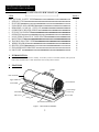
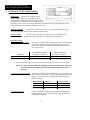
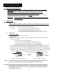
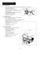
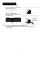
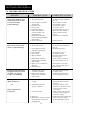
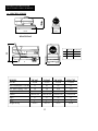
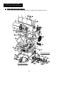
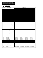
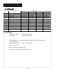
PORTABLE
FORCED AIR HEATERS
“USER’S MANUAL”
DuraHeat®
MODEL:
DFA45
DFA65
DFA120
DFA170T
C
US
C
US
LISTED
Before the first use of this heater, please read this USER’S MANUAL
very carefully. This USER’S MANUAL has been designed to instruct you
as to the proper manner in which to assemble the heater, maintain the
heater, store the heater, and most importantly, how to operate the heater in
a safe and efficient manner. Please keep this manual for future reference.
WORLD MARKETING OF AMERICA, INC.
RT. 22 WEST, P.O. BOX 192
MILL CREEK, PA 17060
1-800-776-9425 (9 AM - 4 PM EST)
MON. - FRI. ONLY
www.yourheater.com
NEVER LEAVE THE HEATER
UNATTENDED WHILE BURNING!
DANGER IMPROPER USE OF THIS HEATER CAN RESULT IN SERIOUS INJURY OR DEATH
FROM BURNS, FIRE, EXPLOSION, ELECTRICAL SHOCK AND/OR CARBON MONOXIDE POISONING.
WARNINGS:
1. RISK OF INDOOR AIR POLLUTION!
• Use this heater only in well ventilated areas. Provide at least a three-square foot (2800 sq. cm.)
opening of fresh outside air for each 100,000 BTU/hr. of heater rating.
• People with breathing problems should consult a physician before using the heater.
• Carbon monoxide poisoning: Early signs of carbon monoxide poisoning resemble the flu, with
headaches, dizziness and/or nausea. If you have these signs, the heater may not be working properly.
Get fresh air at once! Have the heater serviced. Some people are more affected by carbon monoxide
than others. These include pregnant women, persons with heart or lung disease or anemia, those under the
influence of alcohol, or those at high altitudes.
• Never use this heater in living or sleeping areas.
2. RISK OF BURNS/FIRE/EXPLOSION!
• NEVER use any fuel other than 1-K kerosene in this heater. #1 fuel oil is the only acceptable
substitute.
• NEVER use fuel such as gasoline, benzene, paint thinners or other oil compounds in this heater.
(RISK OF FIRE OR EXPLOSION)
• NEVER use this heater where flammable vapors may be present.
• NEVER refill the heaters fuel tank while heater is operating or is still hot.
• This heater is EXTREMELY HOT while in operation. Keep all combustible materials away from heater.
Minimum Clearances: Outlet: 8 feet (250cm) / Sides, top and rear: 4 feet (125cm)
• NEVER block air inlet (rear) or air outlet (front) of heater.
• NEVER use duct work in front or rear of heater.
• NEVER move or handle heater while still hot.
• NEVER transport heater with fuel in it’s tank.
• When used with an optional thermostat or if equipped with a thermostat (DFA170T) heater may start
at any time.
• ALWAYS locate heater on a stable and level surface.
• ALWAYS keep children and animals away from heater.
• Bulk fuel storage should be a minimum of 25 ft. from heaters, torches, portable generators or
other sources of ignition. All fuel storage should be in accordance with federal, state or local
authorities having jurisdiction.
3. RISK OF ELECTRIC SHOCK!
•
•
•
•
Use only the electrical power (voltage and frequency) specified on the model plate of the heater.
Use only a three-prong, grounded outlet and extension cord.
ALWAYS install the heater so that it is not directly exposed to water spray, rain, dripping water or wind.
ALWAYS unplug the heater when not in use.
CALIFORNIA RESIDENTS: This heater produces carbon monoxide, which is listed by the State of
California as a reproductive toxin under Proposition 65.
MASSACHUSETTS RESIDENTS: Massachusetts state law prohibits the use of this heater in any
building which is used in whole or in part for human habitation. Use of this heating device in
Massachusetts requires local fire dept. permit (M.E.L.C. 148, Section 10A.)
CANADIAN RESIDENTS: Use of this heater shall be in accordance with authorities having
jurisdiction and CSA Standard B139.
1
NEVER LEAVE THE HEATER
UNATTENDED WHILE BURNING!
CONTENTS OF USER’S MANUAL
ITEM
PAGE #
PRECAUTIONS - SAFETY GUIDE
1. INTRODUCTION
2. FEATURES
3. UNPACKING AND ASSEMBLY
4. KEROSENE (1-K OR NO. 1 FUEL OIL)
5. OVERVIEW OF HEATER DESIGN
6. FUELING YOUR HEATER
7. OPERATION
8. LONG TERM STORAGE OF YOUR HEATER
9. MAINTENANCE
10. TROUBLE SHOOTING GUIDE
11. WIRING DIAGRAM
12. SPECIFICATIONS
13 EXPLODED PARTS DRAWING
14. PARTS LIST
1
2
2
4
6
7
8
8
9
9
13
14
15
16
17
1. INTRODUCTION
Please read this USER’S MANUAL carefully. It will show you how to assemble, maintain, and operate the
heater safely and efficiently to obtain full benefits from its many built-in features.
2. FEATURES
Handle
Hot Air Outlet
Upper Shell
Fan Guard
Lower Shell
Fuel Gauge
Fuel Cap
Fuel Tank
Side Cover
Power Cord
Lamp
Power/Reset Switch
Figure 1. DFA45/DFA65 MODEL
2
NEVER LEAVE THE HEATER
UNATTENDED WHILE BURNING!
Figure 2. DFA120 MODEL
Handle
Upper Shell
Hot Air Outlet
Upper Shell
Fan Guard
Lower Shell
Fuel Gauge
Fuel Cap
Side Cover
Power Cord
Lamp
Fuel Tank
Power/Reset Switch
Figure 3. DFA170 T MODEL
Handle
Upper Shell
Hot Air Outlet
Upper Shell
Fan Guard
Lower Shell
Fuel Gauge
Power Cord
Fuel Cap
Side Cover
Thermostat Knob
Fuel Tank
Lamp
Power/Reset Switch
3
NEVER LEAVE THE HEATER
UNATTENDED WHILE BURNING!
3. UNPACKING AND ASSEMBLY
1. REMOVE THE HEATER AND ALL PACKING MATERIALS FROM THE BOX. (Fig. 4)
NOTE: Save the shipping carton and packing materials for future storage.
DFA45/ 65
Wheel Support Frame
Wheels
Handle
Screws and Nuts
Axle
Split Pin and Washer
No
No
Yes
Yes
No
No
DFA120
DFA170T
Yes
Yes
Yes
Yes
Yes
Yes
Yes
Yes
Yes
Yes
Yes
Yes
Figure 4. DFA45/DFA65 MODEL
Handle
Screws
Figure 5. DFA120 MODEL/DFA170T MODEL
Wheels
Screws and
Nuts
Handle
Axle
Wheel Support Frame
4
Split Pin and
Plane Washer
NEVER LEAVE THE HEATER
UNATTENDED WHILE BURNING!
2. ASSEMBLING
A. For DFA45/DFA65 Model only (Figure 6)
Screw
Tools Required
• Medium Phillips Screwdriver
1. Align the holes on the upper shell
with the 2 mounting holes on the
handle as shown in Figure 6.
Handle
2. Secure each hole with a screw.
Figure 6
B. For DFA120 and DFA170T only (Figure 7)
These models are furnished with wheels and handles. Wheels, handles, and the mounting
hardware are found in the shipping carton.
Tools Required
• Medium Phillips Screwdriver
• M5 Open or Adjustable Wrench
• Long Nose Pliers
1. Slide axle through wheel support frame. Install wheels on axle.
NOTE: When installing wheels, point extended hub of wheels toward
wheel support frame (see Figure 7)
2. Place plane washers and split pin on axle ends and bend split pins with long
nose pliers to secure.
3. Place heater on wheel support frame. Make sure air inlet end (rear) of heater is
over wheels. Align the holes on fuel tank flange with holes on wheel support frame.
4. Position the handle on top of fuel tank flange. Insert screws through handles, fuel
tank flange, and wheel support frames as shown in Figure 7 and attach nut finger
tight after each screw is inserted.
5. After all screws are inserted, tighten nuts firmly.
CAUTION: DO NOT OPERATE heater without support frame assembled to tank.
5
NEVER LEAVE THE HEATER
UNATTENDED WHILE BURNING!
Handle
Screw
Hot Air Outlet
Fuel Tank Flange
Air Inlet
Wheel Support Frame
Extended Hub
Nut
Wheel
Axle
Plane Washer
Split Pin
Figure 7. Wheel and Handle Assembly, DFA120/DFA170T MODELS ONLY
4. KEROSENE (1-K)
It is EXTREMELY IMPORTANT for the proper operation of this heater that you use the correct grade
of kerosene. The correct grade of kerosene is identified as 1-K kerosene.
1-K Kerosene has been refined to virtually eliminate contaminants such as sulphur, which can cause
a rotten egg odor during operation of the heater. #1 fuel oil may be used if 1-K kerosene is not available.
KEROSENE SHOULD ONLY BE STORED IN A BLUE CONTAINER THAT IS CLEARLY
MARKED “KEROSENE”. NEVER STORE KEROSENE IN A RED CONTAINER.
Red containers are associated with gasoline.
NEVER store kerosene in the living space. Kerosene should be stored in a well ventilated place
outside the living area.
NEVER use any fuel other than 1-K kerosene (#1 fuel oil is an acceptable substitute.)
NEVER use fuel such as gasoline, benzene, alcohol, white gas, camp stove fuel, paint thinners, or
other oil compounds in this heater. These are volatile fuels that can cause explosion or
uncontrolled flames.
NEVER store kerosene in direct sunlight or near a source of heat.
NEVER use kerosene that has been stored from one season to the next. Kerosene deteriorates over
time. “OLD KEROSENE” WILL NOT BURN PROPERLY IN THIS HEATER.
6
NEVER LEAVE THE HEATER
UNATTENDED WHILE BURNING!
5. OVERVIEW OF HEATERS DESIGN
Fuel System:
This heater is equipped with an
electric air pump that forces air through the air line
connected to the fuel intake and then through a nozzle
in the burner head. When the air passes in front of the
fuel intake it causes fuel to rise from the tank and into the burner nozzle. This fuel and air mixture
is then sprayed into the combustion chamber in a fine mist.
“Sure Fire Ignition:
The electronic ignitor sends voltage to a specially designed spark plug.
The spark plug ignites the fuel and air mixture described above.
The Air System:
The heavy duty motor turns a fan that forces air into and around the
combustion chamber. Here the air is heated and then forced out the front of the heater.
The Safety System:
A. Temperature Limit Control:
MODELS
DFA120/DFA170T
DFA45/DFA65
This heater is equipped with a Temperature Limit Control designed
to turn off the heater should the internal temperature rise to an
unsafe level. If this device activates and turns your heater off it
may require service.
Internal Shut-Off Temp.
Plus/Minus 10 Degrees
230˚F/110˚C
176˚F/80˚C
Reset Temperature
Plus/Minus 10 Degrees
194˚F/90˚C
122˚F/50˚C
Once the temperature falls below the reset temperature you will be able to start your heater.
NOTE: For your safety the temperature limiting safety device built into this heater will
allow the heater to run continuously when the ambient temperature is below
80˚F/24˚C.
B. Electrical System Protection:
This heaters electrical system is protected by a fuse mounted to the
PCB Assembly that protects it and other electrical components from
damage. If your heater fails to operate check this fuse first and
replace as needed.
FUSE TYPES:
C. Flame-Out Sensor:
DFA45
DFA65
DFA120
DFA170T
125 volt/2 amps
125 volt/2 amps
125 volt/4 amps
125 volt/5 amps
Utilizes a photocell to monitor the flame in burn chamber during
normal operation. It will cause the heater to shut-off should the
burner flame extinguish.
7
NEVER LEAVE THE HEATER
UNATTENDED WHILE BURNING!
6. FUELING YOUR HEATER
NEVER FILL THE HEATER FUEL TANK IN THE LIVING SPACE: FILL THE TANK
OUTDOORS.
DO NOT OVERFILL YOUR HEATER AND BE SURE HEATER IS LEVELED.
IMPORTANT NOTICE REGARDING FIRST IGNITION OF HEATER:
The first time you light the heater, it should be done outdoors. This allows the oils, etc. used in
manufacturing the heater to burn off outside.
WARNING!!: NEVER REFILL HEATER FUEL TANK WHEN HEATER IS OPERATING
OR STILL HOT.
7. OPERATION
A.)
B.)
VENTILATION
RISK OF INDOOR AIR POLLUTION/USE HEATER ONLY IN WELL VENTILATED AREAS.
Provide a fresh air opening of at least three square feet (2800 sq. cm) for each 100,000 BTU/Hr.
rating. Provide extra fresh air if more heaters are being used.
Example:
A DFA170T heater requires one of the following:
• a two-car garage door raised six inches (15.24 cm)
• a single-car garage door raised nine inches (22.86 cm)
• two, thirty-inch (76.20 cm) windows raised twelve inches (30.48 cm)
OPERATION
TO START HEATER
1. Fill fuel tank with kerosene or No. 1 fuel oil.
2. Attach fuel cap.
3. Plug power cord of heater into three-prong, grounded extension cord. Extension cord must
be at least six feet long.
Extension Cord Wire Size Requirements
• 6 to 10 feet (1.8 to 3 meters) long, use 18 AWG conductor.
• 11 to 100 feet (3.4 to 30.5 meters) long, use 16 AWG conductor.
• 101 to 200 feet (30.8 to 61 meters) long, use 14 AWG conductor.
4. Turn “THERMOSTAT CONTROL Knob” to desired setting (DFA170T) and push power switch
to “ON” position, power indicator lamp will light and heater will start. If heater does not start,
the thermostat setting may be too low, turn “THERMOSTAT CONTROL Knob” to higher position
to start heater. If heater still does not start, turn power switch to “OFF” and then to “ON” position.
(See Figure 8 and 9). If heater still does not start, see Troubleshooting Guide on page 13.
Thermostat Control Knob
Lamp
Lamp
Power/Reset
Switch
Figure 8. DFA45/65/120 Models
NOTE:
Power/Reset
Switch
Figure 9. DFA170T Model
For your safety the temperature limiting safety device built into this heater will allow the
heater to run continuously when the ambient temperature is below 80˚F/24˚C.
NOTICE:The major electrical components of this heater are protected by a safety fuse mounted to
the PCB board. If your heater fails to start, check this fuse first and replace as necessary.
You should also check your power source to insure that proper voltage and frequency are
being supplied to the heater.
8
NEVER LEAVE THE HEATER
UNATTENDED WHILE BURNING!
TO STOP HEATER
1. Turn switch to “OFF” and unplug power cord.
TO RESTART HEATER
1.Wait 10 seconds after stopping heater.
2. Repeat steps under to start heater.
8. LONG TERM STORAGE OF YOUR HEATER
1. Drain fuel tank through fuel cap opening.
2. Using a small amount of kerosene, swirl and rinse the inside of the tank.
NEVER mix water with the kerosene as it will cause rust inside the tank. Pour the kerosene out
making sure that you remove it all.
IMPORTANT: Do not store kerosene over summer months for use during next heating season.
Using old fuel could damage heater.
- Reinstall fuel cap. Properly dispose of old and dirty fuel.
- Store heater in dry well ventilated area. Make sure storage place is free of dust and corrosive fumes.
- Store the heater in the original box with the original packing material and keep the USER’S
MANUAL with the heater.
9. MAINTENANCE
WARNING!!: NEVER SERVICE HEATER WHILE IT IS PLUGGED IN
OR WHILE HOT!
USE ORIGINAL EQUIPMENT REPLACEMENT PARTS. Use of third party
or other alternate components will void warranty and may cause unsafe operating
conditions.
A.) FUEL TANK
FLUSH EVERY 200 HOURS OF OPERATION OR AS NEEDED (SEE STORAGE ABOVE)
B.) AIR INTAKE FILTER
WASH AND DRY WITH SOAP
AND WATER EVERY 500 HOURS
OF OPERATION OR AS NEEDED.
- Remove screws along each side
of heater using M5 nut-driver.
- Lift upper shell off.
- Remove fan guard.
- Wash or replace air intake filter.
- Reinstall fan guard and upper shell.
Upper Shell
Fan
Guard
Air Intake Filter
Figure 10
9
NEVER LEAVE THE HEATER
UNATTENDED WHILE BURNING!
C.) AIR OUTPUT FILTER, LINT FILTER
REPLACE EVERY 500 HOURS OF OPERATION
OR ONCE A YEAR.
- Remove upper shell and fan guard (See page 9).
- Remove filter end cover screws using M5 nut driver.
- Remove filter end cover.
- Replace air output and lint filter.
- Reinstall filter end cover.
- Reinstall fan guard and upper shell.
Air Output Filter
Intake
Filter
Filter End
Cover
Lint Filter
Figure 11.
D.) FAN BLADES
CLEAN EVERY SEASON OR AS NEEDED.
- Remove upper shell (See page 9).
- Use M6 allen wrench to loosen set screw
Motor Shaft
which holds fan blade to motor shaft.
- Slip fan blade off motor shaft.
- Clean fan blade using a soft cloth
moistened with kerosene or solvent.
- Dry fan blade thoroughly.
- Reinstall fan blade on motor shaft. Place
fan blade hub flush with end of motor
shaft.
- Place set screw on flat of shaft. Tighten
set screw firmly (40-50 inch-pounds/4.5-5.6 N-m).
- Reinstall upper shell.
Set screw
Set screw
Motor Shaft
Flush
Fan Blade
Fan
Blade
Figure 12.
E.) NOZZLE
REMOVE DIRT IN NOZZLE AS NEEDED (SEE PAGE 13).
- Remove upper shell (See page 9).
- Remove fan blade (See Section D above).
- Remove fuel and air line hoses from burner head.
- Remove ignitor wire from spark plug. Combustion Chamber
Nozzle Face
- Remove three screws using medium
phillips screwdriver and remove burner
Screw
Nozzle
head from combustion chamber.
Burner Head
- Remove spark plug from burner head
Spark Plug
using medium phillips screwdriver.
Ignitor Wire
- Carefully remove nozzle from burner
Burner
head using 5/8” socket wrench.
Head
- Blow compressed air through face of
Fuel Line Hose
nozzle. (this will remove any dirty in
Air Line Hose
Air Line Fitting
nozzle)
- Reinstall nozzle into burner head
tighten firmly. (80~110 inch-pounds)
Figure 13.
- Install spark plug in burner head.
- Attach burner head to combustion chamber.
- Attach ignitor wire to spark plug.
- Attach fuel and air line hoses to burner head.
- Reinstall fan blade and upper shell.
10
Fuel
Line
Fitting
NEVER LEAVE THE HEATER
UNATTENDED WHILE BURNING!
F.) SPARK PLUG
CLEAN AND REGAP EVERY 600 HOURS OPERATION OR REPLACE AS NEEDED.
- Remove upper shell (See page 9).
- Remove fan (See page 10).
Burner
- Remove ignitor wire from spark plug.
Head
Gap
- Remove spark plug from burner head using medium
phillips screwdriver.
- Clean and regap spark plug electrodes to 3.5mm gap.
- Install spark plug in burner head.
- Attach ignitor wire to spark plug.
Spark Plug
- Reinstall fan and upper shell.
Figure 14.
Ignitor
Wire
G.) PHOTO CELL
CLEAN PHOTOCELLANNUALLY OR AS NEEDED.
- Remove upper shell (See page 9).
- Remove photocell from it’s mounting. Clean with cotton swab.
TO REPLACE: Remove side panel near on/off switch.
- Disconnect wires from circuit board and
remove photocell.
- Install new photocell and attach wires to
circuit board.
- Replace fan and upper shell.
H.)
FUEL FILTER
CLEAN OR REPLACE TWICE A HEATING
SEASON OR AS NEEDED.
- Remove side cover screws using
medium phillips screwdriver.
- Remove side cover.
- Pull fuel line off fuel filter neck.
- Remove fuel filter assembly.
- Wash fuel filter with clean fuel and replace
in tank.
- Attach fuel line to fuel filter neck.
- Reinstall side cover.
Figure 15
Fuel Filter
Fuel Line
Side Cover
Figure 16
11
NEVER LEAVE THE HEATER
UNATTENDED WHILE BURNING!
I.)
PUMP PRESSURE ADJUSTMENT
- Remove pressure gauge plug from filter end cover.
- Install accessory pressure gauge.
- Start heater (See Operation, page 8)
- Adjust pressure (Using a flat blade screwdriver)
Turn relief valve to right to increase pressure. Turn
relief valve to left to decrease pressure. Set pump
pressure as noted below correct pressure for each model.
- Stop heater (See Operation, page 8)
- Remove pressure gauge. Replace pressure gauge
plug in filter end cover.
MODEL
DFA45
DFA65
DFA120
DFA170T
PUMP PRESSURE
3.5 psi
3.5 psi
4.5 psi
6.5 psi
Pressure Gauge
Plug
Relief Valve
Pressure Gauge
Figure 17.
NOTE: USE ONLY ORIGINAL EQUIPMENT REPLACEMENT PARTS.
Use of alternate or third party components will void any warranty and may cause unsafe
operation condition.
12
NEVER LEAVE THE HEATER
UNATTENDED WHILE BURNING!
10.
TROUBLE SHOOTING GUIDE
TROUBLE
Heater ignites but MAIN PCB
assembly shuts heater off after
a short period of time.
(Lamp is flickering)
Heater will not ignite but
motor runs for a short period
of time. (Lamp is flickering)
POSSIBLE CAUSE
1. Wrong pump pressure
2. Dirty Air Output, Air Intake
and Lint Filter
3. Dirty Fuel Filter
4. Dirt in Nozzle
5. Dirty Photocell Lens
6. Photocell Assembly not
properly installed. (Not
seeing the flame)
7. Bad electrical connection
between photocell and MAIN
PCB assembly
8. Defective photocell
1. No fuel in tank
2. Wrong pump pressure
3. Carbon deposits on spark
plug and/or improper gap
4. Dirty fuel filter
5. Dirt in nozzle
6. Water in fuel tank
7. Bad electrical connection
between ignitor and MAIN
PCB assembly
8. Ignitor wire is not attached to
spark plug
9. Defective ignitor
CORRECTIVE ACTION
1. See Pump Pressure Adjustment,
page 12.
2. See Air Output, Air intake
and Lint Filters, page 10.
3. See Fuel Filter, page 11.
4. See Nozzle, page 10.
5. Clean Photocell Lens, page 11.
6. Make sure photocell boot is
properly seated in bracket,
page 11.
7. Check electrical components
8. Replace photocell
1. Fill tank with kerosene
2. See Pump Pressure Adjustment,
page 12.
3. See Spark Plug, page 11.
4. See Fuel Filter, page 11.
5. See Nozzle, page 10.
6. Flush fuel tank with clean
kerosene, page 9.
7. Check electrical connections,
See wiring diagram, page 14.
8. Attach ignitor wire to spark
plug. See Spark Plug, page 11.
9. Replace ignitor.
Fan does not turn when heater
is plugged in and power switch
was in the “ON” position
(Lamp is on or flickering)
1. Thermostat setting is too
low (DFA170T model)
2. Bad electrical connection
between motor and MAIN
PCB assembly
1. Turn thermostat control knob
to a higher setting
2. Check electrical connections,
See Wiring Diagram, page 14.
Heater ignites but shuts off
quickly (Lamp is on)
1. Ambient temperature is
too high
1. Heater cannot be operated in
temperatures above 85˚F/24˚C
See page 7.
2. Turn power switch to “OFF”
and allow to cool (about 10 min.).
Then turn power switch to
“ON” position.
3. Check to insure heater cord and
extension cord are plugged in.
Check power supply.
4. Replace safety fuse in PCB board.
5. Check electrical connections.
See Wiring Diagram, page 14.
OR
Heater will not turn-on
(Lamp is off)
2. Temperature limit safety
device is overheated
3. No electrical power
4. Blown fuse
5. Bad electrical connection between
temperature limit safety device
and PCB board
13
NEVER LEAVE THE HEATER
UNATTENDED WHILE BURNING!
11.
WIRING DIAGRAM
A. WIRING DIAGRAM (DFA45/DFA65)
B. WIRING DIAGRAM (DFA120)
C. WIRING DIAGRAM (DFA170T)
14
NEVER LEAVE THE HEATER
UNATTENDED WHILE BURNING!
12.
SPECIFICATIONS
760cm
300cm
DFA45/DFA65
H
D
W
DFA120 DFA170T
589cm
629cm
853cm
993cm
483cm
522cm
W
D
MODEL
DFA45
DFA65
DFA120
DFA170T
BTU/Hr.
45,000
65,000
120,000
170,000
Fuel Consumption - Gal./Hr.
.35
0.5
0.9
1.3
Fuel Tank Capacity - Gal.
5.0
5.0
10.0
13.0
Pump Pressure PSI
3.5
3.5
4.5
6.5
120VAC/60
120VAC/60
120VAC/60
120VAC/60
Amps
1.7
1.7
2.6
3.3
Phase
1
1
1
1
32/14.5
32/14.5
55/25
62/28
Volt/Hz
Weight lbs./kg.
15
NEVER LEAVE THE HEATER
UNATTENDED WHILE BURNING!
13.
EXPLODED PARTS DRAWING
NOTE: SPECIFY MODEL NUMBER AND PART NUMBER WHEN ORDERING PARTS.
23-1
Motor Pump Assembly
Burner Head Assembly
16
NEVER LEAVE THE HEATER
UNATTENDED WHILE BURNING!
14.
PARTS LIST
KEY NO.
1
2
3
4
5
6
7
8
9
10
11
12
13
14
15
16
16-1
16-2
16-3
16-4
16-5
17
17-1
17-2
17-3
17-4
17-5
17-6
17-7
17-8
17-9
17-10
17-11
17-12
17-13
18
19
DESCRIPTION
Fuel Tank Assembly
Fuel Gauge
Fuel Filter Assembly
Fuel Cap
Power Cord
Power Switch
Display P.C.B. Assembly
Thermostat Control Knob
Lower Shell
Air Line
Temperature Limit Control
Combustion Chamber
Photocell
Fuel Line
Photocell Assembly
Burner Head Assembly
Nozzle
Nozzle Seal Washer
Nozzle Seal Spring
Burner Head
Spark Plug
Motor and Pump Assembly
Motor
Pump Body
Rotor Kit
Blade
End Pump Cover
Filter Kit
Lint Filter
Output Filter
End Filter Cover
Plug/Pump Adj. Kit
Ball
Spring
Adj. Screw
Fan Assembly
Ignitor
DFA45
280-1004-02
282-1001-01
287-4000-20
282-2000-90
140-9000-013
110-9400-001
160-9200-072
----285-5103-00
578-5100-51
154-9000-008
280-8000-02
FA1007
287-5100-50
126-9200-001
Ref.
FA1001
--------284-7112-00
FA1008
283-1000-42
111-9000-985
288-3100-00
FA1000
288-3100-60
288-3100-10
FA1005
See 17-6
See 17-6
288-3100-40
FA1006
See 17-10
See 17-10
See 17-10
283-1000-72
158-9100-001
17
PART NO.
DFA65
DFA120
280-1004-02
280-1004-01
282-1001-01
282-1001-00
287-4000-20
287-4000-21
282-2000-90
282-2000-90
140-9000-013 140-9000-013
110-9400-001 110-9400-001
160-9200-072 160-9200-027
--------285-5103-00
285-5104-00
578-5100-51
287-5100-53
154-9000-008 154-9000-007
280-8000-02
280-8000-01
FA1007
FA1007
287-5100-50
287-5100-52
126-9200-001 126-9200-001
Ref.
Ref.
FA1002
FA1003
----285-8109-90
----285-8110-00
284-7112-00
284-7112-11
FA1008
FA1009
283-1000-42
283-1000-41
111-9000-985
111-9000-984
288-3100-00
288-3100-00
FA1000
FA1000
288-3100-60
288-3100-60
288-3100-10
288-3100-10
FA1005
FA1005
See 17-6
See 17-6
See 17-6
See 17-6
288-3100-40
288-3100-40
FA1006
FA1006
See 17-10
See 17-10
See 17-10
See 17-10
See 17-10
See 17-10
283-1000-72
283-1000-71
158-9100-001 158-9100-007
DFA170T
280-1004-00
282-1001-00
287-4000-21
282-2000-90
140-9000-013
110-9400-001
160-9200-027
285-2103-00
285-5104-20
287-5100-53
154-9000-007
280-8000-00
FA1007
287-5100-52
126-9200-001
Ref.
FA1004
285-8109-90
285-8110-00
284-7112-10
FA1009
283-1000-40
111-9000-955
288-3100-00
FA1000
288-3100-60
288-3100-10
FA1005
See 17-6
See 17-6
288-3100-40
FA1006
See 17-10
See 17-10
See 17-10
283-1000-70
158-9100-009
NEVER LEAVE THE HEATER
UNATTENDED WHILE BURNING!
14.
PARTS LIST
KEY NO.
20
21
22
23
23-1
24
25
26
27
DESCRIPTION
Side Cover R
Side Cover L
Fan Guard
Main P.C.B. Assembly
Fuse
Clip Nut
Upper Shell
Handle
Wheel Assembly
ACCESSORIES
Air Pressure Gauge
Thermostat
DFA45
280-5102-90
280-5102-91
285-3107-40
160-9200-080
FA1015
285-4105-00
285-5103-10
285-3106-80
-----
PART NO.
DFA65
DFA120
280-5102-90
280-5103-01
280-5102-91
280-5103-02
285-3107-40
285-3107-41
160-9200-080 160-9200-071
FA1015
FA1016
285-4105-00
285-4105-00
285-5103-10
285-5104-10
285-3106-80
285-3107-61
----287-6000-01
DFA170T
280-5103-10
280-5103-11
285-3107-41
160-9200-026
FA1017
285-4105-00
285-5104-30
285-3107-60
287-6000-00
FA1010 (all models)
FA1012 (all models)
FOR TECHNICAL ASSISTANCE SEE YOUR LOCAL RETAILER OR
CONTACT US AT:
Phone: 814-643-1775
Tech.: 814-643-2299
Fax: 814-643-3443
Email: [email protected]
or visit our website at www.yourheater.com
18
LIMITED WARRANTY:
This limited warranty is extended to the original retail purchaser of this DuraHeat Heater and warrants against any defect in materials and
workmanship for a period of one (1) year from the date of retail sale. World Marketing of America, Inc., at it's option, will either provide
replacement parts or replace or repair the unit, within one (1) year of retail purchase. (Shipping costs, labor costs, etc. are the responsibility
of the purchaser.)
DO NOT RETURN TO RETAILER UNTILCONTACTING WORLD MARKETING AT 1-800-776-9425,
FAX: 814-643-3443, EMAIL: [email protected] OR MAIL: P.O. BOX 192, MILLCREEK PA 17060
DUTIES OF THE OWNER:
This heating appliance must be operated in accordance with the written instructions furnished with this heater. This warranty shall not
excuse the owner from properly maintaining this heater in accordance with the written instructions furnished with this heater. A bill of sale,
canceled check or payment record must be kept to verify purchase date and establish warranty period. Original carton should be kept in case
of warranty return of unit.
WHAT IS NOT COVERED:
1. Damage resulting from use of improper fuel.
2. Damage caused by misuse or use contrary to the owners manual and safety guidelines.
3. Damaged caused by lack of normal maintenance.
4. Air filters, fuel filters, fuses.
5. Use of non-standard parts or accessories.
6. Damage caused in transit.
This warranty does not imply or assume any responsibility for consequential damages that may result from the use, misuse, lack of routine
maintenance of this heating appliance. A cleaning fee and the cost of parts may be charged for appliance failures resulting from lack of
maintenance. This warranty does not cover claims which do not involve defective workmanship or materials. Freight charges on warranty
parts orheaters to and from the factory shall be the responsibility of the owner. FAILURE TO PERFORM GENERAL
MAINTENANCE (INCLUDING CLEANING) WILLVOID THIS WARRANTY.
THIS LIMITED WARRANTYIS GIVEN TO THE PURCHASER IN LIEU OF ALLOTHER WARRANTIES, EXPRESSED OR
IMPLIED, INCLUDING BUTNOT LIMITED TO THE WARRANTIES OF MERCHANTABILITY OF FITNESS FOR A PARTICULAR
PURPOSE. THE REMEDYPROVIDED IN THIS WARRANTYIS EXCLUSIVE AND IS GRANTED IN LIEU OF ALLOTHER
REMEDIES. IN NO EVENTWILLWORLD MARKETING OF AMERICABE LIABLE FOR INCIDENTALOR CONSEQUENTIAL
DAMAGES.
Some states do not allow limitations on how long an implied warranty lasts, so the above limitation may not apply to you. Some states do
not allow the exclusion or limitation of incidental or consequential damages so the above limitation or exclusion may not apply to you.
CLAIMS HANDLED AS FOLLOWS:
1. Contact our Consumer Warranty Dept. noting the heater model, the problem, copy of the sales receipt or date of purchase. The
Warranty Dept. can be reached at 1-800-776-9425, Fax at 814-643-3443 or email at [email protected].
2. A representative will contact you. DO NOT RETURN THE HEATER TO RETAILER unless instructed by our Representative.
This warranty gives you specific legal rights and you may also have other rights which vary from state to state.
DO NOTRETURN THE HEATER TO THERETAILERWITHOUTPRIORINSTRUCTION FROM OURREPRESENTATIVE.
TO REGISTER THE WARRANTYON YOUR NEW KEROSENE HEATER, PLEASE FILL OUT THIS CARD
COMPLETELY AND MAIL WITHIN 14 DAYS FROM DATE OF PURCHASE.
NAME:
ADDRESS:
CITY:
STATE:
MODEL:
SERIAL #:
DEALER PURCHASED FROM:
CITY & STATE WHERE PURCHASED:
PHONE: (
)
ZIP:
DATE PURCHASED:
TYPE OF STORE:
PRICE PAID:
Please Take a Minute To Give Us YourAnswers To The Following Questions.
All Responses Are Used Solely For Market Research And Are Held In Strict Confidence.
Do you own any other portable heaters?
Yes
No
If you do: How many?
What Brands?
Satisfied?
Please indicate your age group:
Under 25,
25-34,
35-44,
45-54,
55-64,
65 or older
How do you intend to use your new heater?
Where did you hear about this heater?
What made you select this heater?
Price,
Store Display,
Salesperson,
Recommendation,
Radio ad,
Newspaper Ad,
Other (Please Specify)
What is your occupation?
Part No. DHF-WTY
Would you recommend this heater to a friend?
THANK YOU FOR COMPLETING THIS FORM!