1
Introduction
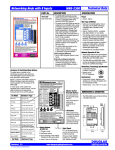
WRS-2224 Programmable Relay Scanner /
WNX-2624 Network Node
24V Transformer
Connections
Group Input Connections
· 5 available, each controlling one
relay group.
· Up to 6 low-voltage switching
Relay Output Connections
·
24 outputs, 12 per side.
·
The relay scanner can be
programmed with the built-in keypad
to switch a group of relay outputs
when signaled by an input from any
scanner in the network.
·
Each output group can support the
FLICK WARN switching option, while
only one group can be programmed
to support the TIME OUT option.
devices can be connected in
parallel to each input.
· Separate electrically isolated 24V
return connections provided for
groups 1, 2 & 3 and for groups
4 & 5.
Digital Link Connection
· Connect the network node to the
·
·
scanner, as shown.
LED indicator is ON when the node
is plugged into the scanner.
Power must be disconnected from
the scanner when plugging or
unplugging the node.
LookUp Buttons
· Press the NODE ID button and hold
for 3 seconds to display the node's
network address (1-24) on the
scanner.
· Press the SWITCH CODE button and
·
Service & Unconfigure Pin
· Press and hold for 3 seconds with
hold for 3 seconds to display on the
scanner (in binary code) the network
address of the selected scanner
switch input.
WINK LED, which is activated by the
network wink command, is disabled
by pressing SWITCH CODE button.
scanner in Program mode to delete
groups and return to default settings.
· Press and hold for 3 seconds with
·
scanner in Normal mode to unconfigure
the node.
Indicator LED flashes continually when
the node is unconfigured. Indicator LED
flashes on 3 seconds and off 1 second
when the node is defective.
Network Manager Select Switch
· Select one network node to be the Network
· Connect #16 AWG, unshielded
·
· Polarity insensitive.
·
Manager by setting its switch to ON position.
Indicator LED is ON when the node is
correctly set as Network Manager.
Except for the Network Manager node, this switch
must be set to OFF for all nodes in the network.
LonWorks Self-Configured: Directions & Applications
page 1
Digital Signal Connection
twisted pair data signal.
lighting controls