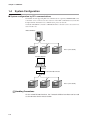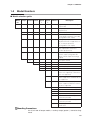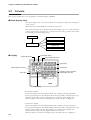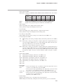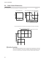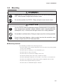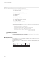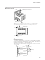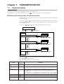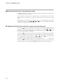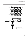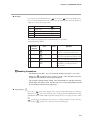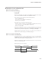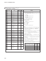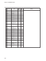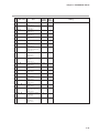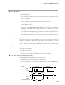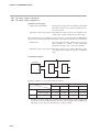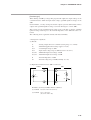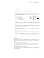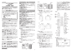
1
No. CP-UM-1757E DCP31 DIGITRONIK Digital Program Controller User's Manual Thank you for purchasing the DCP31 DIGITRONIK Digital Program Controller. This manual contains information for ensuring correct use of the DCP31. It also provides necessary information for installation, maintenance, and troubleshooting. This manual should be read by those who design and maintain devices that use the DCP31. Be sure to keep this manual nearby for handy reference. RESTRICTIONS ON USE This product has been designed, developed and manufactured for general-purpose application in machinery and equipment. Accordingly, when used in applications outlined below, special care should be taken to implement a fail-safe and/or redundant design concept as well as a periodic maintenance program. • Safety devices for plant worker protection • Start/stop control devices for transportation and material handling machines • Aeronautical/aerospace machines • Control devices for nuclear reactors Never use this product in applications where human safety may be put at risk. REQUEST Make sure that this User's Manual is handed over to the user before the product is used. Copying or duplicating this User's Manual in part or in whole is forbidden. The information and specifications in this User's Manual are subject to change without notice. Considerable effort has been made to ensure that this User's Manual is free from inaccuracies and omissions. If you should find any inaccuracies or omissions, please contact Yamatake Corporation. In no event is Yamatake Corporation liable to anyone for any indirect, special or consequential damages as a result of using this product. 1996 Yamatake Corporation ALL RIGHTS RESERVED DIGITRONIKTM, DCPTM, and SDCTM are trademarks of Yamatake Corporation in Japan. SAFETY REQUIREMENTS To reduce risk of electric shock which could cause personal injury, follow all safety notices in this documentation. This symbol warns the user of a potential shock hazard where hazardous live voltages may be accessible. • • • • • • If the equipment is used in a manner not specified by the manufacturer, the protection provided by the equipment must be impaired. Do not replace any component (or part) not explicity specified as replaceable by your supplier. All wiring must be in accordance with local norms and carried out by authorized and experienced personnel. The ground terminal must be connected before any other wiring (and disconnected last). A switch in the main supply is required near the equipment. Mains power supply wiring requires a (T) 1.0A, 250V fuse(s). EQUIPMENT RATINGS Supply voltages : 100 to 240Vac (operation power voltages 90 to 264Vac) Frequency : 50/60Hz Power consumption : 30VA maximum EQUIPMENT CONDITIONS Do not operate the instrument in the presence of flammable liquids or vapors. Operation of any electrical instrument in such an environment constitutes a safety hazard. Temperature : 0 to 50˚C Humidity : 10 to 90%RH Vibration : Frequency 10 to 60Hz Acceleration 1.96m/s2 maximum Over-voltage category : Category II(IEC60364-4-443, IEC60664-1) Pollution degree :2 EQUIPMENT INSTALLATION • The controller must be mounted into a panel to limit operator access to the rear terminals. • Specification of common mode voltage: The common mode voltages of all I/O except for main supply are less than 33Vrms, 46.7V peak and 70Vdc. APPLICABLE STANDARD EN61010-1, EN61326 CAUTION Danger of explosion if battery is incorrectly replaced. Replace only with the same or equivalent type recommended by the manufacturer. Dispose of used batterries according to the manufacturer’s instructions. i SAFETY PRECAUTIONS ■ About Icons The safety precautions described in this manual are indicated by various icons. Please be sure you read and understand the icons and their meanings described below before reading the rest of the manual. Safety precautions are intended to ensure the safe and correct use of this product, to prevent injury to the operator and others, and to prevent damage to property. Be sure to observe these safety precautions. WARNING Warnings are indicated when mishandling this product might result in death or serious injury. CAUTION Cautions are indicated when mishandling this product might result in minor injury to the user, or only physical damage to the product. ■ Examples Use caution when handling the product. The indicated action is prohibited. Be sure to follow the indicated instructions. ii WARNING Before removing or mounting the DCP31, be sure to turn the power OFF. Failure to do so might cause electric shock. Do not disassemble the DCP31. Doing so might cause electric shock or faulty operation. Before connecting the DCP31 to the measurement target or external control circuits, make sure that the FG terminal is properly grounded (100Ω max.). Failure to do so might cause electric shock or fire. Turn the DCP31 OFF before starting wiring. Failure to do so might cause electric shock. Do not touch electrically charged parts such as the power terminals. Doing so might cause electric shock. CAUTION Use the DCP31 within the operating ranges recommended in the specifications (temperature, humidity, voltage, vibration, shock, mounting direction, atmosphere, etc.). Failure to do so might cause fire or faulty operation. Do not block ventilation holes. Doing so might cause fire or faulty operation. Do not allow lead clippings, chips or water to enter the DCP31 case. Doing so might cause fire or faulty operation. Wire the DCP31 properly according to predetermined standards. Also wire the DCP31 using designed power leads according to recognized installation methods. Failure to do so might cause electric shock, fire or faulty operation. Inputs to the current input terminals 31 and 33 on the DCP31 should be within the current and voltage ranges listed in the specifications. Failure to do so might cause fire or faulty operation. Firmly tighten the terminal screws at the torque listed in the specifications. Insufficient tightening of terminal screws might cause electric shock or fire. Do not use unused terminals on the DCP31 as relay terminals. Doing so might cause electric shock, fire or faulty operation. We recommend attaching the terminal cover (sold separately) after wiring the DCP31. Failure to do so might cause electric shock. iii CAUTION Use the relays on the DCP31 within the service life listed in the specifications. Continued use of the relays after the recommended service life might cause fire or faulty operation. Use Yamatake SurgeNon if there is the risk of power surges caused by lightning. Failure to do might cause fire or faulty operation. Before replacing the battery, be sure to turn the power OFF. Failure to do so might cause electric shock. Do not touch internal components immediately after turning the power OFF to replace the battery. Doing so might cause burns. ・ Do not insert the battery with the polarities (+, -) reversed. ・ Do not use damaged (broken battery skin, leaking battery fluid) batteries. ・ Do not throw batteries into fires, or charge, short-circuit, disassemble or heat batteries. ・ Store batteries in low-temperature, dry locations. Failure to observe the above cautions may cause batteries to emit heat or split, or battery fluid to leak. Store batteries out of the reach of small children. Batteries are small and are easy to swallow. If a child swallows a battery, consult a physician immediately. When disposing of used batteries at the user site, observe bylaws. If you touch components inside the DCP31, touch a grounded metal object to discharge any static electricity from your body. Otherwise, static electricity might damage the components. Handling Precautions After turning the power ON, do not operate the DCP31 for at least 15 seconds to allow the DCP31 to stabilize. iv Unpacking Check the following when removing the DCP31 from its package: 1. Check the model No. to make sure that you have received the product that you ordered. 2. Check the DCP31 for any apparent physical damage. 3. Check the contents of the package against the Package List to make sure that all accessories are included in the package. After unpacking, handle the DCP31 and its accessories taking care to prevent damage or loss of parts. If an inconsistency is found or the package contents are not in order, immediately contact your dealer. Product List Name Model No. Body Q’ty Remarks 1 See 1-5 How Model Nos. Are Configured, page 1-5. The Model No. is the parts No. for two installation tools. Mounting bracket 81405411-001 1 set (2) User's Manual CP-UM-1757E 1 Unit indicator label (SI units) N-3132 1 This manual Request The filter on the front of the controller is Covered with a protective film to protect the surface of the controller. When you have finished mounting and wiring the controller, fix cellophane adhesive tape on the corners of the filter, and pull in the direction of the arrow to peel off the protective film. Pull towards you. Handling Precautions Peeling off the protective film with your fingernail might scratch the surface of the controller. v The Role of This Manual Two manuals have been prepared for the DCP31. Read the manual according to your specific requirements. The lists below all the manuals that accompany the DCP31 and gives a brief outline of the manual. If you do not have the required manual, contact Yamatake Corporation or your dealer. DCP31 DIGITRONIK Digital Program Controller User's Manual No.CP-UM-1757E This manual. This manual is provided with the DCP31 (single-loop model). It is required reading for those in charge of designing, producing and maintaining control systems incorporating the DCP31, and for those using the DCP31 in other applications. It describes mounting onto control panels, wiring, parameter setup, program setup, operation methods, maintenance and inspection, troubleshooting and specifications. DIGITRONIK CPL Communication DCP31/32 User's Manual No.CP-SP-1066E This manual is required reading for those using the CPL communications functions of the DCP31/32. This manual describes an outline of CPL communications, wiring, communications procedures and DCP31/32 communications data, how to remedy trouble, and communications specifications. vi Organization of This User’s Manual This manual is organized as follows: Chapter 1. GENERAL This chapter describes DCP31 applications, features and basic function blocks. It also gives a list of model numbers. Chapter 2. NAMES & FUNCTIONS OF PARTS This chapter describes the names and functions of DCP31 parts, input types and range Nos. Chapter 3. MOUNTING This chapter describes how to mount the DCP31 on control panels. This chapter is required reading for designers of control systems using the DCP31. Chapter 4. WIRING This chapter describes the precautions when wiring the DCP31 to a control system and how to wire the DCP31. This chapter is required reading for designers of control systems and supervisors of wiring work. Chapter 5. FUNCTIONS This chapter describes the functions of the controller. This chapter is required reading for designers of control systems using the DCP31. Chapter 6. OPERATION This chapter describes how to switch the basic display states of the DCP31, and select and run programs. This chapter is required reading for designers of control systems using the DCP31 and users of the DCP31. Chapter 7. PARAMETER SETUP This chapter describes how to set up parameters on the controller and the meaning of settings. Chapter 8. PROGRAM SETUP This chapter describes how to set up programs on the controller and the meanings of settings. Chapter 9. MAINTENANCE & TROUBLESHOOTING This chapter describes points to check when the DCP31 is not working properly or how to remedy trouble that might occur. Chapter 10. SPECIFICATIONS This chapter describes the general specifications, performance specifications and external dimensions of the DCP31. vii Contents SAFETY REQUIREMENTS SAFETY PRECAUTIONS Unpacking Request The Role of This Manual Organization of This User's Manual Conventions Used in This Manual Chapter 1. GENERAL 1-1 1-2 1-3 1-4 Features . . . . . . . . . . . . . . . . . . . . . . . . . . . . . . . . . . . . . . . . . . . . . . . . . . . . . . . 1-1 Basic Function Blocks . . . . . . . . . . . . . . . . . . . . . . . . . . . . . . . . . . . . . . . . . . . 1-2 Data Structure . . . . . . . . . . . . . . . . . . . . . . . . . . . . . . . . . . . . . . . . . . . . . . . . . . 1-3 System Configuration. . . . . . . . . . . . . . . . . . . . . . . . . . . . . . . . . . . . . . . . . . . . 1-4 ■ System configuration by CPL communications . . . . . . . . . . . . . . . . . . . 1-4 1-5 Model Numbers . . . . . . . . . . . . . . . . . . . . . . . . . . . . . . . . . . . . . . . . . . . . . . . . . 1-5 ■ Model selection guide . . . . . . . . . . . . . . . . . . . . . . . . . . . . . . . . . . . . . . . . 1-5 Chapter 2. NAMES & FUNCTIONS OF PARTS 2-1 Structure . . . . . . . . . . . . . . . . . . . . . . . . . . . . . . . . . . . . . . . . . . . . . . . . . . . . . . 2-1 2-2 Console . . . . . . . . . . . . . . . . . . . . . . . . . . . . . . . . . . . . . . . . . . . . . . . . . . . . . . . 2-2 ■ Basic display state . . . . . . . . . . . . . . . . . . . . . . . . . . . . . . . . . . . . . . . . . . . 2-2 ■ Display . . . . . . . . . . . . . . . . . . . . . . . . . . . . . . . . . . . . . . . . . . . . . . . . . . . . . 2-2 ■ Keys . . . . . . . . . . . . . . . . . . . . . . . . . . . . . . . . . . . . . . . . . . . . . . . . . . . . . . . 2-4 ■ Functions using two or more keys . . . . . . . . . . . . . . . . . . . . . . . . . . . . . . 2-7 ■ Loader jack . . . . . . . . . . . . . . . . . . . . . . . . . . . . . . . . . . . . . . . . . . . . . . . . . 2-7 2-3 Input Type and Range No. . . . . . . . . . . . . . . . . . . . . . . . . . . . . . . . . . . . . . . . . 2-8 ■ Inputs . . . . . . . . . . . . . . . . . . . . . . . . . . . . . . . . . . . . . . . . . . . . . . . . . . . . . . 2-8 Chapter 3. MOUNTING 3-1 External Dimensions . . . . . . . . . . . . . . . . . . . . . . . . . . . . . . . . . . . . . . . . . . . . 3-1 3-2 Panel Cutout Dimensions . . . . . . . . . . . . . . . . . . . . . . . . . . . . . . . . . . . . . . . . 3-2 3-3 Mounting . . . . . . . . . . . . . . . . . . . . . . . . . . . . . . . . . . . . . . . . . . . . . . . . . . . . . . 3-3 ■ Mounting locations. . . . . . . . . . . . . . . . . . . . . . . . . . . . . . . . . . . . . . . . . . . 3-3 ■ Noise generating sources and countermeasures . . . . . . . . . . . . . . . . . . 3-4 ■ Dust-proof cover. . . . . . . . . . . . . . . . . . . . . . . . . . . . . . . . . . . . . . . . . . . . . 3-4 ■ Mounting method . . . . . . . . . . . . . . . . . . . . . . . . . . . . . . . . . . . . . . . . . . . . 3-5 Chapter 4. WIRING 4-1 4-2 4-3 4-4 4-5 Wiring Precautions . . . . . . . . . . . . . . . . . . . . . . . . . . . . . . . . . . . . . . . . . . . . . . 4-1 Compensating Lead . . . . . . . . . . . . . . . . . . . . . . . . . . . . . . . . . . . . . . . . . . . . . 4-3 Terminal Connections . . . . . . . . . . . . . . . . . . . . . . . . . . . . . . . . . . . . . . . . . . . 4-4 Layout of Terminals and Recommended Lead Draw-out Direction . . . . . . . 4-5 Connecting the Ground and Power Supply . . . . . . . . . . . . . . . . . . . . . . . . . . 4-6 ■ Power supply . . . . . . . . . . . . . . . . . . . . . . . . . . . . . . . . . . . . . . . . . . . . . . . 4-6 ■ Ground. . . . . . . . . . . . . . . . . . . . . . . . . . . . . . . . . . . . . . . . . . . . . . . . . . . . . 4-6 viii 4-6 Wiring of Standard and Add-on Terminal Base . . . . . . . . . . . . . . . . . . . . . . . 4-7 ■ Standard terminal layout . . . . . . . . . . . . . . . . . . . . . . . . . . . . . . . . . . . . . . 4-7 ■ Add-on terminal layout. . . . . . . . . . . . . . . . . . . . . . . . . . . . . . . . . . . . . . . . 4-7 4-7 Connecting Inputs (analog inputs) . . . . . . . . . . . . . . . . . . . . . . . . . . . . . . . . . 4-8 ■ Connecting input 1 . . . . . . . . . . . . . . . . . . . . . . . . . . . . . . . . . . . . . . . . . . . 4-8 4-8 Connecting control outputs (outputs 1, 2) . . . . . . . . . . . . . . . . . . . . . . . . . . . 4-9 ■ Relay output (0D) . . . . . . . . . . . . . . . . . . . . . . . . . . . . . . . . . . . . . . . . . . . . 4-9 ■ Current output (5G) . . . . . . . . . . . . . . . . . . . . . . . . . . . . . . . . . . . . . . . . . . 4-9 ■ Position-proportional output (2G). . . . . . . . . . . . . . . . . . . . . . . . . . . . . . . 4-9 ■ Voltage output (6D). . . . . . . . . . . . . . . . . . . . . . . . . . . . . . . . . . . . . . . . . . 4-10 ■ Heat/cool output (3D) . . . . . . . . . . . . . . . . . . . . . . . . . . . . . . . . . . . . . . . . 4-10 ■ Heat/cool output (5K) . . . . . . . . . . . . . . . . . . . . . . . . . . . . . . . . . . . . . . . . 4-10 4-9 Connecting auxiliary outputs (outputs 2, 3). . . . . . . . . . . . . . . . . . . . . . . . . 4-11 ■ 0D, 5G, 6D auxiliary outputs . . . . . . . . . . . . . . . . . . . . . . . . . . . . . . . . . . 4-11 ■ 2G, 3D, 5K auxiliary outputs . . . . . . . . . . . . . . . . . . . . . . . . . . . . . . . . . . 4-11 4-10 Connecting Event Output (relay output). . . . . . . . . . . . . . . . . . . . . . . . . . . . 4-12 4-11 Connecting Time Event Output (open-collector) . . . . . . . . . . . . . . . . . . . . . 4-13 4-12 Connecting External Switch (RSW) Input. . . . . . . . . . . . . . . . . . . . . . . . . . . 4-14 4-13 Connecting for Communications . . . . . . . . . . . . . . . . . . . . . . . . . . . . . . . . . 4-16 ■ RS-485 interface . . . . . . . . . . . . . . . . . . . . . . . . . . . . . . . . . . . . . . . . . . . . 4-16 4-14 Isolating Inputs and Outputs . . . . . . . . . . . . . . . . . . . . . . . . . . . . . . . . . . . . . 4-19 ■ Control outputs 0D, 5G, 6D, 3D, 5K. . . . . . . . . . . . . . . . . . . . . . . . . . . . . 4-19 ■ Control output 2G . . . . . . . . . . . . . . . . . . . . . . . . . . . . . . . . . . . . . . . . . . . 4-19 Chapter 5. FUNCTIONS 5-1 Data . . . . . . . . . . . . . . . . . . . . . . . . . . . . . . . . . . . . . . . . . . . . . . . . . . . . . . . . . . 5-1 ■ Data types . . . . . . . . . . . . . . . . . . . . . . . . . . . . . . . . . . . . . . . . . . . . . . . . . . 5-1 5-2 Program Patterns . . . . . . . . . . . . . . . . . . . . . . . . . . . . . . . . . . . . . . . . . . . . . . . 5-2 ■ Patterns . . . . . . . . . . . . . . . . . . . . . . . . . . . . . . . . . . . . . . . . . . . . . . . . . . . . 5-2 ■ Events 1 to 3, Time events 1 to 5 . . . . . . . . . . . . . . . . . . . . . . . . . . . . . . . 5-6 ■ PID set selection . . . . . . . . . . . . . . . . . . . . . . . . . . . . . . . . . . . . . . . . . . . . . 5-8 ■ G.Soak (guarantee soak) . . . . . . . . . . . . . . . . . . . . . . . . . . . . . . . . . . . . . . 5-9 ■ PV start . . . . . . . . . . . . . . . . . . . . . . . . . . . . . . . . . . . . . . . . . . . . . . . . . . . 5-10 ■ Cycle . . . . . . . . . . . . . . . . . . . . . . . . . . . . . . . . . . . . . . . . . . . . . . . . . . . . . 5-10 ■ Pattern link . . . . . . . . . . . . . . . . . . . . . . . . . . . . . . . . . . . . . . . . . . . . . . . . 5-11 5-3 Modes . . . . . . . . . . . . . . . . . . . . . . . . . . . . . . . . . . . . . . . . . . . . . . . . . . . . . . . 5-12 ■ Mode type . . . . . . . . . . . . . . . . . . . . . . . . . . . . . . . . . . . . . . . . . . . . . . . . . 5-12 ■ Mode transition . . . . . . . . . . . . . . . . . . . . . . . . . . . . . . . . . . . . . . . . . . . . . 5-14 ■ Mode transition operations . . . . . . . . . . . . . . . . . . . . . . . . . . . . . . . . . . . 5-15 ■ Mode transition limitations . . . . . . . . . . . . . . . . . . . . . . . . . . . . . . . . . . . 5-16 5-4 Controller and Programmer . . . . . . . . . . . . . . . . . . . . . . . . . . . . . . . . . . . . . . 5-17 5-5 Input Processing Functions. . . . . . . . . . . . . . . . . . . . . . . . . . . . . . . . . . . . . . 5-18 5-6 Output Processing Functions . . . . . . . . . . . . . . . . . . . . . . . . . . . . . . . . . . . . 5-19 ■ Control output. . . . . . . . . . . . . . . . . . . . . . . . . . . . . . . . . . . . . . . . . . . . . . 5-19 ■ SP output. . . . . . . . . . . . . . . . . . . . . . . . . . . . . . . . . . . . . . . . . . . . . . . . . . 5-23 ■ Auxiliary output . . . . . . . . . . . . . . . . . . . . . . . . . . . . . . . . . . . . . . . . . . . . 5-23 ix Chapter 6. OPERATION 6-1 Turning the Power ON . . . . . . . . . . . . . . . . . . . . . . . . . . . . . . . . . . . . . . . . . . . 6-1 6-2 Switching the Basic Display . . . . . . . . . . . . . . . . . . . . . . . . . . . . . . . . . . . . . . 6-2 ■ Display in program operation mode . . . . . . . . . . . . . . . . . . . . . . . . . . . . . 6-3 ■ Display in constant-value operation mode . . . . . . . . . . . . . . . . . . . . . . . 6-5 6-3 Program Selection . . . . . . . . . . . . . . . . . . . . . . . . . . . . . . . . . . . . . . . . . . . . . . 6-7 ■ How to select the program No. . . . . . . . . . . . . . . . . . . . . . . . . . . . . . . . . . 6-7 6-4 External Switch (RSW) Operations . . . . . . . . . . . . . . . . . . . . . . . . . . . . . . . . . 6-8 ■ External switch (RSW) inputs . . . . . . . . . . . . . . . . . . . . . . . . . . . . . . . . . . 6-8 ■ Program selection . . . . . . . . . . . . . . . . . . . . . . . . . . . . . . . . . . . . . . . . . . . 6-9 ■ Read timing . . . . . . . . . . . . . . . . . . . . . . . . . . . . . . . . . . . . . . . . . . . . . . . . 6-10 6-5 Manual Operation and Auto-tuning. . . . . . . . . . . . . . . . . . . . . . . . . . . . . . . . 6-11 ■ Manual operation . . . . . . . . . . . . . . . . . . . . . . . . . . . . . . . . . . . . . . . . . . . 6-11 ■ Auto-tuning (AT) . . . . . . . . . . . . . . . . . . . . . . . . . . . . . . . . . . . . . . . . . . . . 6-11 Chapter 7. PARAMETER SETUP 7-1 Parameter Setup . . . . . . . . . . . . . . . . . . . . . . . . . . . . . . . . . . . . . . . . . . . . . . . . 7-1 ■ Selecting the setting group in the parameter setup . . . . . . . . . . . . . . . . 7-1 ■ Moving individual items in the parameter setup . . . . . . . . . . . . . . . . . . 7-2 ■ Changing individual items and how to return from the setup state . . . 7-2 7-2 How to Use PARA . . . . . . . . . . . . . . . . . . . . . . . . . . . . . . . . . . . . . . . . . . . . . . . . 7-4 ■ How to register functions to keys . . . . . . . . . . . . . . . . . . . . . . . . . . . . . . . 7-4 7-3 Parameter Setup List . . . . . . . . . . . . . . . . . . . . . . . . . . . . . . . . . . . . . . . . . . . . 7-7 ■ Variable parameter settings “p a R a” . . . . . . . . . . . . . . . . . . . . . . . . . . . 7-7 ■ Description of variable parameter settings . . . . . . . . . . . . . . . . . . . . . . 7-10 ■ Event configuration data settings “e v” . . . . . . . . . . . . . . . . . . . . . . . . . 7-18 ■ Description of event configuration data. . . . . . . . . . . . . . . . . . . . . . . . . 7-27 ■ PID parameter settings “p i d” . . . . . . . . . . . . . . . . . . . . . . . . . . . . . . . . 7-28 ■ Setup data settings “S e t” . . . . . . . . . . . . . . . . . . . . . . . . . . . . . . . . . . . 7-32 ■ Description of setup data settings . . . . . . . . . . . . . . . . . . . . . . . . . . . . . 7-38 ■ Table data settings “T B L” . . . . . . . . . . . . . . . . . . . . . . . . . . . . . . . . . . . . 7-45 ■ Description of table data settings . . . . . . . . . . . . . . . . . . . . . . . . . . . . . . 7-46 ■ Constant-value operation data settings “C N S T” . . . . . . . . . . . . . . . . . 7-47 Chapter 8. PROGRAM SETUP 8-1 Program Setup . . . . . . . . . . . . . . . . . . . . . . . . . . . . . . . . . . . . . . . . . . . . . . . . . 8-1 ■ How to enter program setup . . . . . . . . . . . . . . . . . . . . . . . . . . . . . . . . . . . 8-1 ■ Selecting the program No. to set up . . . . . . . . . . . . . . . . . . . . . . . . . . . . . 8-1 ■ Mode transition . . . . . . . . . . . . . . . . . . . . . . . . . . . . . . . . . . . . . . . . . . . . . . 8-2 ■ Programming map . . . . . . . . . . . . . . . . . . . . . . . . . . . . . . . . . . . . . . . . . . . 8-4 ■ Display details. . . . . . . . . . . . . . . . . . . . . . . . . . . . . . . . . . . . . . . . . . . . . . . 8-5 ■ Setting up pattern items. . . . . . . . . . . . . . . . . . . . . . . . . . . . . . . . . . . . . . . 8-5 ■ Setting up events 1 to 3 items . . . . . . . . . . . . . . . . . . . . . . . . . . . . . . . . . . 8-6 ■ Setting up time events 1 to 5 . . . . . . . . . . . . . . . . . . . . . . . . . . . . . . . . . . . 8-8 ■ Setting up PID set No. items . . . . . . . . . . . . . . . . . . . . . . . . . . . . . . . . . . 8-10 ■ Setting up G.Soak (guarantee soak) items. . . . . . . . . . . . . . . . . . . . . . . 8-11 ■ Setting up G.Soak time-out items . . . . . . . . . . . . . . . . . . . . . . . . . . . . . . 8-11 x ■ Setting up PV start items . . . . . . . . . . . . . . . . . . . . . . . . . . . . . . . . . . . . . 8-12 ■ Setting up cycle items . . . . . . . . . . . . . . . . . . . . . . . . . . . . . . . . . . . . . . . 8-12 ■ Setting up pattern link items . . . . . . . . . . . . . . . . . . . . . . . . . . . . . . . . . . 8-13 ■ Deleting programs . . . . . . . . . . . . . . . . . . . . . . . . . . . . . . . . . . . . . . . . . . 8-14 ■ Inserting and deleting segments. . . . . . . . . . . . . . . . . . . . . . . . . . . . . . . 8-15 8-2 Copying Programs . . . . . . . . . . . . . . . . . . . . . . . . . . . . . . . . . . . . . . . . . . . . . 8-16 ■ Operation. . . . . . . . . . . . . . . . . . . . . . . . . . . . . . . . . . . . . . . . . . . . . . . . . . 8-16 8-3 General Reset . . . . . . . . . . . . . . . . . . . . . . . . . . . . . . . . . . . . . . . . . . . . . . . . . 8-17 ■ Operation. . . . . . . . . . . . . . . . . . . . . . . . . . . . . . . . . . . . . . . . . . . . . . . . . . 8-17 Chapter 9. MAINTENANCE & TROUBLESHOOTING 9-1 Maintenance . . . . . . . . . . . . . . . . . . . . . . . . . . . . . . . . . . . . . . . . . . . . . . . . . . . 9-1 9-2 Self-diagnostics and Alarm Code Display . . . . . . . . . . . . . . . . . . . . . . . . . . . 9-2 ■ Self-diagnostics at power ON . . . . . . . . . . . . . . . . . . . . . . . . . . . . . . . . . . 9-2 ■ Self-diagnostics at each sampling cycle . . . . . . . . . . . . . . . . . . . . . . . . . 9-2 ■ Intermittent self-diagnostics during operation . . . . . . . . . . . . . . . . . . . . 9-2 ■ Self-diagnostics only when certain functions are operating . . . . . . . . . 9-3 ■ Alarm code display. . . . . . . . . . . . . . . . . . . . . . . . . . . . . . . . . . . . . . . . . . . 9-3 ■ Alarm categories. . . . . . . . . . . . . . . . . . . . . . . . . . . . . . . . . . . . . . . . . . . . . 9-3 9-3 Trouble during Key Entry. . . . . . . . . . . . . . . . . . . . . . . . . . . . . . . . . . . . . . . . . 9-4 ■ The program No. does not change by pressing PROG in basic display state . . . . . . . . . . . . . . . . . . . . . . . . . . . . . . . . . . . . . . . . . . . . . . . . . . . . . . . 9-4 ■ The program No. does not change by pressing in the basic display state . . . . . . . . . . . . . . . . . . . . . . . . . . . . . . . . . . . . . . . . . . . . . . . . 9-4 ■ The controller does not change to RUN mode by pressing RUN/HOLD in the basic display state . . . . . . . . . . . . . . . . . . . . . . . . . . . . . . . . . . . . . . . . 9-4 ■ The controller does not change to HOLD mode by pressing RUN/HOLD in the basic display state . . . . . . . . . . . . . . . . . . . . . . . . . . . . . . . . . . . . . . . . 9-4 ■ The controller cannot be reset by pressing PROG + RUN/HOLD in the basic display state . . . . . . . . . . . . . . . . . . . . . . . . . . . . . . . . . . . . . . . . . . . . . . . . 9-4 ■ The program is not advanced by pressing PROG + DISP in the basic display state . . . . . . . . . . . . . . . . . . . . . . . . . . . . . . . . . . . . . . . . . . . . . . . . 9-5 ■ The controller does not change to FAST mode by pressing FUNC + in the basic display state . . . . . . . . . . . . . . . . . . . . . . . . . . . . . . . . . . . . . . 9-5 A/M ■ The controller does not change to MANUAL mode by pressing in the basic display state . . . . . . . . . . . . . . . . . . . . . . . . . . . . . . . . . . . . . . 9-5 A/M ■ The controller does not change to AUTO mode by pressing in the basic display state . . . . . . . . . . . . . . . . . . . . . . . . . . . . . . . . . . . . . . . . 9-5 AT ■ Auto-tuning (AT) is not started by pressing in the basic display state . . . . . . . . . . . . . . . . . . . . . . . . . . . . . . . . . . . . . . . . . . . . . . . . . . . . . . . 9-5 AT ■ Auto-tuning (AT) is not canceled by pressing in the basic display state . . . . . . . . . . . . . . . . . . . . . . . . . . . . . . . . . . . . . . . . . . . . . . . . . . . . . . . 9-6 ■ Setting group other than “p a R a” is not displayed by pressing PARA by selecting the setting group in parameter set state . . . . . . . . . . . . . . 9-6 ■ Setting group other than “S e t” is not displayed by pressing PARA by selecting the setting group in parameter set state . . . . . . . . . . . . . . . . . 9-6 xi ENT ■ The controller does not enter the setting entry state by pressing in the parameter setup state . . . . . . . . . . . . . . . . . . . . . . . . . . . . . . . . . . . 9-6 ■ The controller does not change to setup group selection state and setting entry state continues by pressing PARA in parameter setting entry state . . . . . . . . . . . . . . . . . . . . . . . . . . . . . . . . . . . . . . . . . . . . . . . . . . 9-6 ■ The controller does not change to program setup state by pressing FUNC + PROG in the basic display state . . . . . . . . . . . . . . . . . . . . . . . . . . . . 9-6 ■ The controller does not change to the setting entry state by pressing ENT in the basic display state . . . . . . . . . . . . . . . . . . . . . . . . . . . . . . . . . . 9-6 ■ Items cannot be changed by pressing , in program setup state . . . . . . . . . . . . . . . . . . . . . . . . . . . . . . . . . . . . . . . . . . . . . . . . . . . . . . . 9-7 ■ Event items cannot be changed by repeatedly pressing , in program setup state . . . . . . . . . . . . . . . . . . . . . . . . . . . . . . . . . . . . . . . . . . 9-7 ■ Time events cannot be changed by repeatedly pressing , in program setup state . . . . . . . . . . . . . . . . . . . . . . . . . . . . . . . . . . . . . . . . . . 9-7 ■ PID set items cannot be changed by repeatedly pressing , in program setup state . . . . . . . . . . . . . . . . . . . . . . . . . . . . . . . . . . . . . . . . . 9-7 ■ G.Soak items cannot be changed by repeatedly pressing , in program setup state . . . . . . . . . . . . . . . . . . . . . . . . . . . . . . . . . . . . . . . . . . 9-7 ■ PV start items, cycle items and pattern link items cannot be displayed by repeatedly pressing , in program setup state . . . . . . . . . . . 9-7 ■ Insertion/deletion of segments cannot be confirmed by pressing ENT FUNC + in program setup state. . . . . . . . . . . . . . . . . . . . . . . . . . . . . . 9-8 ■ Program deletion cannot be confirmed by pressing FUNC + CLR while entering pattern items in program setup state . . . . . . . . . . . . . . . . . . . . 9-8 ■ The program cannot be copied by pressing + PROG in the basic display state . . . . . . . . . . . . . . . . . . . . . . . . . . . . . . . . . . . . . . . . . . . . . . . . 9-8 ■ General reset is not applied by pressing FUNC + CLR + DISP in the basic display state . . . . . . . . . . . . . . . . . . . . . . . . . . . . . . . . . . . . . . . . . . . . . . . . 9-8 9-4 Motor Adjustment is Impossible . . . . . . . . . . . . . . . . . . . . . . . . . . . . . . . . . . . 9-9 ■ Normal wiring for direct motor rotation . . . . . . . . . . . . . . . . . . . . . . . . . 9-10 ■ Normal wiring for reverse motor rotation. . . . . . . . . . . . . . . . . . . . . . . . 9-10 ■ Alarm display caused by wrong wiring and causes . . . . . . . . . . . . . . . 9-10 9-5 Replacing the Battery . . . . . . . . . . . . . . . . . . . . . . . . . . . . . . . . . . . . . . . . . . . 9-11 ■ BAT LED blinking . . . . . . . . . . . . . . . . . . . . . . . . . . . . . . . . . . . . . . . . . . . 9-11 ■ Replacing the battery . . . . . . . . . . . . . . . . . . . . . . . . . . . . . . . . . . . . . . . . 9-11 ■ Replacement procedure. . . . . . . . . . . . . . . . . . . . . . . . . . . . . . . . . . . . . . 9-12 Chapter 10. SPECIFICATIONS 10-1 Specifications . . . . . . . . . . . . . . . . . . . . . . . . . . . . . . . . . . . . . . . . . . . . . . . . . 10-1 ■ Accessories/option list . . . . . . . . . . . . . . . . . . . . . . . . . . . . . . . . . . . . . . 10-7 10-2 External Dimensions . . . . . . . . . . . . . . . . . . . . . . . . . . . . . . . . . . . . . . . . . . . 10-8 ■ Soft dust-proof cover set . . . . . . . . . . . . . . . . . . . . . . . . . . . . . . . . . . . . . 10-9 ■ Hard dust-proof cover set . . . . . . . . . . . . . . . . . . . . . . . . . . . . . . . . . . . . 10-9 ■ Terminal cover set . . . . . . . . . . . . . . . . . . . . . . . . . . . . . . . . . . . . . . . . . . 10-9 Index xii Conventions Used in This Manual The following conventions are used in this manual: Handling Precautions : Handling Precautions indicate items that the user should pay attention to when handling the DCP31. Note : Notes indicate useful information that the user might benefit by knowing. DISP PROG : These icons represent keys on the DCP31’s console. + RUN/HOLD : Combinations of icons like these indicate that while holding (1) (2) (3) PROG RUN/HOLD must be pressed down. : The numbers with the parenthesis indicate steps in a sequence or indicate corresponding parts in an explanation. : Indicates the controller state after an operation. xiii Chapter 1. GENERAL Chapter 1. GENERAL 1-1 Features The DCP31 is a general-purpose single-loop program controller for controlling temperature, pressure, flow rate and other inputs. ● High accuracy achieved by multi-range input Multi-range input allows you to choose between the following input types: thermocouple, resistance temperature detector (RTD), dc voltage and dc current. Accuracy of ±0.1%FS±1 digit and a sampling cycle of 0.1s ensures consistently high-precision control. ● Wide range of control output types A wide range of models supporting various control output types are available: relay timeproportional output, position-proportional output, current output, voltage time-proportional output, and heat/cool output. On models other than heat-cool control output, you can also choose neural net-based auto-tuning and smart-tuning for inhibiting overshoot, in addition 2 degrees of freedom PID. ● Enhanced compatibility with PLC 12 external switch inputs (eight optional), three event outputs and five time event outputs (optional) ensure compatibility with automating systems designed around a PLC core. ● Easy operation Up to eight frequently changed parameter setups can be registered to the tating recall of item setups. PARA key, facili- If the Smart Loader Package (sold separately) is used together with the DCP31, programs and parameters can be set up on a personal computer. 1-1 Chapter 1. GENERAL 1-2 Basic Function Blocks Input • Square root extraction • Linearization table approximation • Bias • Filter • Thermocouple • Resistance temperature detector • dc current • dc voltage 4 external switch inputs • RUN • HOLD • RESET • ADV 8 external switch inputs Outputs Control Operation Block • Mode transition • PID control • Auto-tuning • Neuro & Fuzzy • Forward/reverse action • ON-OFF control • Output change limitter • Upper/lower limitter • SP output • Current • Relay • Voltage • Position-proportional • Heat-cool Event Outputs • PV • SP • Deviation • MV • MFB • Modes • Alarm • SP limit • SP bias * • Program No. • FAST • PV start • AUTO/MANUAL • AT • G.Soak cancel • Direct/reverse action * Time Event Outputs • Time event • Segment code Key operation * Auxiliary Outputs • Display selection • Program No. • RUN/HOLD • RESET • ADV • FAST • AUTO/MANUAL • AT • Program setup • Parameter setup • PV • SP • Deviation • MV • MFB CPL communications I/O * MFB input Loader communications I/O 1-2 Program Parameters • 19 patterns x 30 segments • Events • Time events • PID sets • G.Soak • PV start • Cycle • Pattern link • Variable parameters • Event configuration • PID parameters (8 sets) • Setup • Tables • Constant-value operation * indicates options. Chapter 1. GENERAL 1-3 Data Structure Data is made up of “parameters” that are used mainly for setting controller functions and “programs” that are used for setting operation during program operation of the controller. • Total of 19 program patterns Program No.=19 Number of segments=8 3 SP 2 4 5 6 Program No.=3 Number of segments=15 8 SP Program No.=2 Number of segments=19 Program No.=1 18 5 19 4 3 12 Time 13 14 15 Number of segments=6 SP 7 Time 6 2 Time 1 Time • Parameters Variable parameters Event configuration data PID parameters Setup data Table data Constant-value operation data 1-3 Chapter 1. GENERAL 1-4 System Configuration ■ System configuration by CPL communications On DCP31 models supporting RS-485 communications (optional), DIGITRONIK series controllers can be connected as slave stations on the CPL communications (Controller Peripheral Link: Yamatake host communication protocol) network. Yamatake MA500 FA controller or MX200 machine controller can be used as the host station in this case. MA500 or MX200 RS-485 DCP31 (slave station) Personal computer RS-232C RS-232C/RS-485 Converter RS-485 DCP31 (slave station) Handling Precautions On the 3-lead RS-485 interface, the Yamatake CMC10L001A000 can be used as the converter for the master station. 1-4 Chapter 1. GENERAL 1-5 Model Numbers ■ Model selection guide Basic Model No. Output Function Power Option 1 Option Additions Description 2 P31A Digital Program Controller (singleloop model) 0D Relay outputs (on-off, or timeproportional) 2G Position-proportional output 5G Current output (controller/programmer selectable) (changeable to 6D output) 6D Voltage output (current value adjustment function supported, onoff, or time-proportional) (changeable to 5D output) 3D Heat-cool output, relay output + relay output (PID control or 3position-proportional) 5K Heat-cool output, current output + current output (changeable between current output and voltage output) 0 One input channel AS Free power supply (90 to 264Vac) 00 No auxiliary output 01 1 auxiliary output 02 2 auxiliary outputs 0 External switch inputs (4), time events not supported, communications not supported 1 External switch inputs (12), 5 time events supported, communications not supported 2 External switch inputs (12), 5 time events supported, RS-485 communications supported 00 Additional treatment not supported T0 Tropical treatment K0 Antisulfide treatment D0 Inspection Certificate supplied B0 Additional treatment + Inspection Certificate provided L0 Antisulfide treatment + Inspection Certificate provided Y0 Complying with the traceability certification Handling Precautions On 2G, 3D and 5K output models, 2 auxiliary output (option 1) cannot be designated. 1-5 Chapter 1. GENERAL This page left intentionally blank 1-6 Chapter 2. NAMES & FUNCTIONS OF PARTS Chapter 2. NAMES & FUNCTIONS OF PARTS 2-1 Structure This controller comprises a body, console, case, standard terminal base and add-on terminal base. Case Console Contains 7-segment display, LEDs, operation keys and loader connector. Body Contains console and electrical circuits. Standard terminal base Connectors for connecting power, input, output, event outputs, external switch inputs (4) and auxiliary outputs (options) Add-on terminal base Terminal for connecting external switch inputs (8 options), time event outputs (options) and CPL communications (options). The add-on terminal base is provided only on models that support optional external switch inputs (8) and time event outputs. Lock screw Fixes the case to the body. Key cover Cover for preventing erroneous operation. 2-1 Chapter 2. NAMES & FUNCTIONS OF PARTS 2-2 Console The console comprises keys for operating the controller, displays and LEDs. ■ Basic display state The “basic display state” is the state in which the controller operating state is displayed on the console. When the power is turned ON, the controller is in this state. Key operation changes the controller from the basic display state to one of the parameter setup, program setup, program copy or general reset states. Key operation also returns the controller to the basic display state. Power ON Parameter setups Program setups Basic display states Program copy General reset ■ Display Segment No. display Program No. display Basic indicator LED lamps Upper display Lower display Mode indicator LED lamps Low battery voltage LED (BAT) Control/output state LED Event LEDs Profile display • Program No. display In the basic display state, this display indicates the currently selected program No. In the program setup state, this display indicates the program No. currently being set up. During constant-value operation, this display goes out in the basic display state. When an alarm occurs in the basic display state, alarm code “A L” is displayed. • Segment No. display In the basic display state, this display indicates the currently selected segment No. In the program setup state, this display indicates the segment No. currently being set up. During constant-value operation, this display goes out in the basic display state. In the parameter setup state, this display indicates the item No. When an alarm occurs in the basic display state, the alarm code No. is displayed. 2-2 Chapter 2. NAMES & FUNCTIONS OF PARTS • Mode indicator LEDs RUN, HLD : Display the READY, RUN, HOLD, FAST and END modes. (See following table.) Mode LED RUN HLD MAN PRG READY RUN HOLD FAST END Out Lit Out Blinking Out Out Out Lit Out Blinking : Lights in the MANUAL mode, and goes out in the AUTO mode. : Lights in the program setup state. Otherwise, this LED is out. • Upper display In the basic display state, displays PV and other values. In the parameter setup state, displays the item code. • Lower display In the basic display state, displays SP, time, output and other values. In the parameter setup state, displays the item setting value. • Low battery voltage LED BAT: Blinks when the battery voltage is low. Otherwise, this LED is out. • Control/output state LED AT: Blinks during auto-tuning, and lights during smart-tuning. Otherwise, this LED is out. OT1: When relay or voltage are assigned to output 1, lights when output is ON and goes out when output is OFF. In the case of 2G output models, lights when the openside relay is ON and goes out when the relay is OFF. Lights when current output is assigned to output 1. OT2: When relay or voltage are assigned to output 2, lights when output is ON and goes out when output is OFF. In the case of 2G output models, lights when the closedside relay is ON and goes out when the relay is OFF. Lights when current output is assigned to output 2, and goes out when auxiliary output is assigned to output 2. OT3: Out • Basic indicator LEDs PV: Lights during PV display. Otherwise, this LED is out. SP: Lights during SP display. Otherwise, this LED is out. OUT: Lights during output display. Otherwise, this LED is out. TM: Lights during time display. Otherwise, this LED is out. CYC: Lights during cycle display. Otherwise, this LED is out. CH1: Out CH2: Out • Event LEDs EV1, EV2, : • In the basic display state or parameter setup state, light when each of EV3 events1 to 3 are ON, and go out when OFF. • In the program setup (programming) state, light when each of the items for events 1 to 3 are displayed. Otherwise, these LEDs are out. T1, T2, T3, : • Light when each of time events 1 to 5 are ON, and go out when OFF. T4, T5 • In the program setup (programming) state, light when each of the items for time events 1 to 5 are displayed. Otherwise, these LEDs are out. • Profile display Displays the tendencies (rise, soak, fall) of the program pattern. Blinks during G.soak standby, and lights successively after the power is turned ON. 2-3 Chapter 2. NAMES & FUNCTIONS OF PARTS ■ Keys PROG FUNC DISP : Program key : Display key : Function key : Left arrow key, right arrow key : Up arrow key, down arrow key Loader jack A/M : Auto/Manual key AT : Auto-tuning key RUN/HOLD CLR PARA : Run/Hold key : Clear key : Parameter key ENT : Enter key Category Basic display state Function Key operation To change the display DISP To change the program No. in ascending order (in READY mode) PROG To execute running of program (in READY mode) To run the program (in READY, HOLD, FAST modes) RUN/HOLD To hold the program (in RUN mode) To reset the program (in READY, HOLD, FAST, END modes) PROG To advance the program (in RUN, HOLD, FAST modes) PROG To run the program fast (in RUN, HOLD modes) FUNC To execute manual operation (in AUTO mode) A/M To execute automatic operation (in MANUAL mode) To start auto-tuning (when not executing auto-tuning) To cancel auto-tuning (when executing auto-tuning) To change values during manual operation (when MV or SP is blinking) 2-4 AT + RUN/HOLD + DISP + Chapter 2. NAMES & FUNCTIONS OF PARTS Category Function Parameter setup Starts parameter setup. So the controller enters selection of setup group (major item). (in basic display state) FUNC To change the setup group (major item) PARA To fix the setup group Key operation + PARA ENT To moves between individual items (minor items) To start changing individual item setting values (while setting value is blinking) ENT To end changing individual item setting values (while setting value is blinking) To change individual item setting values (while setting value is blinking) To cancel changing individual item setting values (in basic display state) PARA To selects setup group To end parameter setup PARA key Assignment item setup To start changing assignment item setting values (in basic display state) DISP PARA To move to next item by assignment item, and start changing setting values To change assignment item setting values (while setting value is blinking) To end changing assignment item setting values (while setting value is blinking) ENT To start changing assignment item setting values Program setup To end assignment item setup DISP To start program setup (programming) (in basic display state) FUNC + PROG To move between program items and segment Nos. To start changing item setting values (while setting value is blinking) ENT To end changing item setting values (while setting value is blinking) To change item setting values (while setting value is blinking) To clear item setting (while setting value is blinking) FUNC To cancel changing item setting values (while setting value is blinking) DISP To insert/delete segments FUNC To change the program No. in ascending order FUNC To change the program No. in descending order FUNC To end program setup (programming) DISP + + + CLR ENT PROG + 2-5 Chapter 2. NAMES & FUNCTIONS OF PARTS Category Program copy Function Key operation To start program copy (in basic display state) PROG + To change the copy destination program No. General reset To execute program copy (while setting value is blinking) ENT To end program copy DISP To check general reset (in basic display state) FUNC To execute general reset ENT To cancel general reset DISP + CLR + DISP Handling Precautions Do not operate the console keys using a sharp-pointed object such as a propelling pencil or needle. Doing so might damage the console. 2-6 Chapter 2. NAMES & FUNCTIONS OF PARTS ■ Functions using two or more keys PROG + RUN/HOLD : Reset keys Press RUN/HOLD with PROG held down in the basic display state to reset the controller. The controller enters the READY mode in the RUN, HOLD, FAST or END modes. The controller cannot be reset in the READY mode by key operation. PROG + DISP : Advance keys Press DISP with PROG held down in the program operation mode in the basic display state to advance the program. In the RUN, HOLD or FAST modes, the program advances to the next segment. The controller cannot advance in the READY mode by key operation. FUNC + FUNC + PARA : Parameter setup keys Press PARA with FUNC held down in the basic display state to move to selection of the setting group (major items) in the parameter setup state. FUNC + PROG : Program setup (programming) keys Press PROG with FUNC held down in the program operation mode in the basic display state to move to the program setup (programming) state. Press PROG with FUNC held down in the program setup state to change the No. of the program to be set up in ascending order. FUNC + FUNC + CLR : Program item delete keys Press CLR with FUNC held down during entry of settings in the program setup state to clear the setting. FUNC + ENT : Segment insert/delete keys Press ENT with FUNC held down at SP or time item in the program setup state to move to the segment insert/delete screen. PROG : Program copy keys Press PROG with held down in the program operation READY mode in the basic display state to move to the program copy screen. + FUNC + : Fast keys Press with FUNC held down in the program operation mode in the basic display state to fast-operate the program. The controller enters the FAST mode from the RUN or HOLD modes. : Program No. change keys Press with FUNC held down in the program setup state to change the No. of the program to be set up in descending order. CLR + DISP : General reset keys Press CLR and DISP with FUNC held down in the READY AUTO mode in the basic display state to move to the general reset confirmation screen. ■ Loader jack This jack is for connecting the loader. Objects other than the loader plug should not be inserted into this jack. The loader jack is not isolated from internal digital circuits. Be sure to cap the loader jack when it is not in use. 2-7 Chapter 2. NAMES & FUNCTIONS OF PARTS 2-3 Input Type and Range No. ■ Inputs ● Thermocouple Input Format Range No. Code Temp. Range (°C) Temp. Range (°F) K (CA) 0 K09 0 to 1200 0 to 2400 K (CA) 1 K08 0.0 to 800.0 0 to 1600 K (CA) 2 K04 0.0 to 400.0 0 to 750 K (CA) 3 K29 -200 to +1200 -300 to +2400 K (CA) 4 K44 -200.0 to +300.0 -300 to +700 K (CA) 5 K46 -200.0 to +200.0 -300 to +400 E (CRC) 6 E08 0.0 to 800.0 0 to 1800 J (IC) 7 J08 0.0 to 800.0 0 to 1600 T (CC) 8 T44 B (PR30-6) 9 B18 0 to 1800 0 to 3300 R (PR13) 10 R16 0 to 1600 0 to 3100 S (PR10) 11 S16 0 to 1600 0 to 3100 W (WRe5-26) 12 W23 0 to 2300 o to 4200 W (WRe5-26) 13 W14 0 to 1400 0 to 2552 PR40-20 14 D19 0 to 1900 0 to 3400 Ni-Ni-Mo 15 Z13 0 to 1300 32 to 2372 N 16 U13 0 to 1300 32 to 2372 PL II 17 Y13 0 to 1300 32 to 2372 DIN U 18 Z08 -200.0 to +400.0 -300 to +750 DIN L 19 Z07 -200.0 to +800.0 -300 to +1600 Golden iron chromel 20 Z06 -200.0 to +300.0 0.0 to +300.0K -300 to +700 — ● Resistance temperature detector (RTD) Input Format Temp. Range (°C) Temp. Range (°F) JIS’89 Pt100 32 F50 -200.0 to +500.0 -300 to +900 (IEC Pt100Ω) 33 F46 -200.0 to +200.0 -300 to +400 34 F32 -100.0 to +150.0 -150.0 to +300.0 35 F36 -50.0 to +200.0 -50.0 to +400.0 36 F38 -60.0 to +40.0 -76.0 to +104.0 37 F33 -40.0 to +60.0 -40.0 to +140.0 38 F05 0.0 to 500.0 0.0 to 900.0 39 F03 0.0 to 300.0 0.0 to 500.0 40 F01 0.00 to 100.00 0.0 to 200.0 48 P50 -200.0 to +500.0 -300 to +900 49 P46 -200.0 to +200.0 -300 to +400 50 P32 -100.0 to +150.0 -150.0 to +300.0 51 P36 -50.0 to +200.0 -50.0 to +400.0 52 P38 -60.0 to +40.0 -76.0 to +104.0 53 P33 -40.0 to +60.0 -40.0 to +140.0 54 P05 0.0 to 500.0 0.0 to 900.0 55 P03 0.0 to 300.0 0.0 to 500.0 56 P01 0.00 to 100.00 0.0 to 200.0 JIS’89 J Pt100 2-8 Range No. Code Chapter 2. NAMES & FUNCTIONS OF PARTS ● dc current, dc voltage Input Format Range No. Code 4 to 20mA 64 C01 0 to 20mA 65 C08 0 to 10mA 66 M01 -10 to +10mV 67 L02 0 to 100mV 68 L01 0 to 1V 69 L04 -1 to +1V 70 L08 1 to 5V 71 V01 0 to 5V 72 L05 0 to 10V 73 L07 Range (programmable) -1999 to +9999 Handling Precautions • The unit of code Z06 is Kelvin (K) • The lower limit readout of code B18 is 20°C (68°F). The lower limit readout (°C) of codes K44, K46, T44, Z08 and Z07 is -199.9°C. • The lower limit readout (°C) of codes F50, F46, P50 and P46 is -199.9°C. • The upper limit readout (°C) of codes F01 and P01. • The PV lower limit alarm does not occur with code F50. However, note that the PV lower limit alarm occurs at a disconnection when input has been downscaled when input is disconnected during setup. • The number of digits past the decimal point for dc current and dc voltage is programmable within the range 0 to 3. 2-9 Chapter 2. NAMES & FUNCTIONS OF PARTS This page left intentionally blank 2-10 Chapter 3. MOUNTING Chapter 3. MOUNTING External Dimensions Unit: mm (18) 159.5 15 137 96 A B A B (106x104) 96 Mounting bracket 81405411-001 Soft dust-proof cover set (sold separately) 81446087-001 Hard dust-proof cover set (sold separately) 81446083-001 Terminal cover set (sold separately) 81446084-001 110.5 B-B 90.2 A-A 91.5 3-1 Terminal screw 37 78.4 Back plate Add-on terminal base 3-1 Chapter 3. MOUNTING 3-2 Panel Cutout Dimensions Use a steel panel of at least 2mm in thickness for mounting the controller. Panel cutout dimensions during multiple mounted (recommended) 92+0.8 0 92+0.8 0 Panel cutout dimensions Unit: mm 92+0.8 0 46 96 x (N - 1) 46 96 x N - 4 N=number of units installed Panel cutout dimensions when mounting units horizontally and vertically (recommended) 150min.(when vertically mounted) 99 min. (when horizontally mounted) (107 min. when hard dust-prevention cover is used) Handling Precautions When mounting the controller, take care to prevent the temperature at the lower surface of the controller’s case from exceeding the operating temperature range (0 to 50°C), particularly when mounting vertically or during multiple mounting. 3-2 Chapter 3. MOUNTING 3-3 Mounting WARNING Before wiring, or removing/mounting the DCP31, be sure to turn the power OFF. Failure to do so might cause electric shock. Do not disassemble the DCP31. Doing so might cause electric shock. CAUTION Use the DCP31 within the operating ranges recommended in the specifications (temperature, humidity, voltage, vibration, shock, mounting direction, atmosphere, etc.). Failure to do so might cause fire or faulty operation. Do not block ventilation holes. Doing so might cause fire or faulty operation. Do not allow lead clippings, chips or water to enter the controller case. Doing so might cause fire or faulty operation. ■ Mounting locations Avoid installing the DCP31 in the following locations: • Locations outside of the operating temperature range (0 to 50°C) and operating humidity range (10 to 90%RH) • Locations subject to sulfide gas or other flammable gases • Locations subject to dust or oil smoke • Locations subject to the direction sunlight, wind or rain • Locations that directly subject the body to vibration or impact • Locations under high-voltage lines, near welders or near sources of electrical noise • Locations near (within 15m) of high-voltage ignition equipment such as boilers • Locations where magnetic fields are generated • Locations subject to flammable liquids or moisture 3-3 Chapter 3. MOUNTING ■ Noise generating sources and countermeasures • Generally, the following generate electrical noise: (1) Relays and contacts (2) Solenoid coils, solenoid valves (3) Power lines (in particular, 90Vac min.) (4) Induction loads (5) Inverters (6) Motor commutators (7) Phase angle control SCR (8) Wireless communications equipment (9) Welding equipment (10) High-voltage ignition equipment • If the influence of electrical noise cannot be eliminated, we recommend taking the following countermeasures: - Provision of a CR filters for fast-rising noise Recommended CR filter:Yamatake Model No. 81446365-001 - Provision of a varister for noise with a high wave height Recommended varister: Yamatake Model No. 81446366-001 (100V) 81446367-001 (200V) Handling Precautions The varister may become short-circuited when trouble occurs. Pay attention to this when providing a varister on a controller. ■ Dust-proof cover Use the dust-proof cover when using the controller in a dusty or dirty location, and to prevent inadvertent operation. Two dust proof-covers are provided, hard or soft, each with the following differing functions: Type Confirmation on Display Hard Soft indicates that a function can be used. 3-4 Operation x Chapter 3. MOUNTING ■ Mounting method Panel Mounting bracket 81405411-001 Mounting bracket • Firmly secure the top and bottom of the controller by the mounting brackets. • When mounting the controller, secure by lower mounting bracket (1) first. (2) Mounting bracket Panel Panel (1) Handling Precautions To secure the controller, tighten the screw on the mounting bracket (supplied) until there is no more play and then tighten a further full turn. Take care not to overtighten the screw. Doing so might deform the case. • Keep the mounting angle to within 10° from the horizontal at both the controller rear top and bottom. Lift up from rear by 10° max. Pull down from rear by 10° max. 3-5 Chapter 3. MOUNTING This page left intentionally blank 3-6 Chapter 4. WIRING Chapter 4. WIRING 4-1 Wiring Precautions WARNING Before connecting the DCP31 to the measurement target or external control circuits, make sure that the FG terminal is properly grounded (100Ω max.). Failure to do so might cause electric shock or fire. Before wiring, or removing/mounting the DCP31, be sure to turn the power OFF. Failure to do so might cause electric shock. Do not touch electrically charged parts such as the power terminals. Doing so might cause electric shock. CAUTION Wire the DCP31 properly according to predetermined standards. Also wire the DCP31 using designed power leads according to recognized installation methods. Failure to do so might cause electric shock, fire or faulty operation. Do not allow lead clippings, chips or water to enter the DCP31 case. Doing so might cause fire or faulty operation. Inputs to the current input terminals ( 31 ) and ( 33 ) on the DCP31 should be within the current and voltage ranges listed in the specifications. Failure to do so might cause electric shock or faulty operation. Firmly tighten the terminal screws at the torque listed in the specifications. Insufficient tightening of terminal screws might cause electric shock or fire. Do not use unused terminals on the DCP31 as relay terminals. Failure to do so might cause electric shock, fire or faulty operation. We recommend attaching the terminal cover (sold separately) after wiring the DCP31. Failure to do so might cause electric shock, fire or faulty operation. Use the relays on the DCP31 within the service life listed in the specifications. Continued use of the relays after the recommended service life might cause fire or faulty operation. Use Yamatake SurgeNon if there is the risk of power surges caused by lightning. Failure to do might cause fire or faulty operation. 4-1 Chapter 4. WIRING Handling Precautions • Before wiring the DCP31, check the controller catalog No. and terminal Nos. on the label on the rear of the body. After wiring the DCP31, be sure to check the wiring for any mistakes. • Maintain a distance of at least 50cm between I/O leads or communications leads and the power lead. Also, do not pass these leads through the same piping or wiring duct. • When wiring with crimped terminals, take care to prevent contact with adjacent terminals. • When connecting the DCP31’s thermocouples in parallel to other controllers, make sure that the total input impedance of the other controller is at least 1MΩ. If the input impedance is less than 1MΩ, the DCP31 may not be able to detect sensor disconnection. • When inputting the DCP31’s I/O (parallel connection in case of input) to an A/D converter or analog scanner, read data may fluctuate. To prevent this, adopt one of the following measures. (1) Use a low-speed, integrating type A/D converter. (2) Insert an isolator without a switching power supply between the DCP31 and A/D converter. (3) Average data on a personal computer when reading data. (4) If possible, set a filter for the input. • Provide the wiring for the instrument power supply with a mains power shutoff switch within reach of the instrument operator. • Provide the wiring for the instrument power supply with a delayed operation type (T) 1A current rating, 250V voltage rating fuse. (IEC 127) • Devices and systems to be connected to this unit must have the basic insulation sufficient to withstand the maximum operating voltage levels of the power supply and input/output parts. 4-2 Chapter 4. WIRING 4-2 Compensating Lead In the case of thermocouple input, connect the bare thermocouple lead to the terminal. If the thermocouple is located a long way from the DCP31 or the thermocouple is connected to a terminal, extend the connection using a compensating lead and then connect to the terminal. Use shielded compensating leads only. • For I/O other than thermocouples, use JCS4364 instrument cable or equivalent product. (This is generally referred to “twisted shielded cable for instruments.”) The following cables are recommended. Fujikura Ltd. 2-core IPEV-S-0.9mm2 x 1P 3-core ITEV-S-0.9mm2 x 1T Hitachi Cable Ltd. 2-core KPEV 0.9mm2 x 1P 3-core KTEV-S-0.9mm2 x 1T • Shielded, multi-core microphone cord (MVVS) can be used if there is little electromagnetic induction. 4-3 Chapter 4. WIRING 4-3 Terminal Connections Use crimped terminals that fit onto M3.5 screws. 7.3 max. 7.4 Unit: mm 6.6 max. 3.7dia. Handling Precautions • When installing the DCP31 in locations subject to vibration or impact, be sure to use round crimped terminals to prevent the lead from coming loose from the terminal. • When wiring with crimped terminals, take care to prevent contact with adjacent terminals. • The recommended tightening torque for the terminal screws is 0.78 to 0.98N•m. 4-4 Chapter 4. WIRING 4-4 Layout of Terminals and Recommended Lead Draw-out Direction Wiring is carried out on the standard terminal base or add-on terminal base. The following diagram shows the recommended draw-out directions for the leads on the standard terminal base: The lead draw-out directions are the same when using the add-on terminal base. 1 11 21 26 2 12 22 27 3 13 23 28 4 14 24 29 5 15 25 30 6 16 31 7 17 32 8 18 33 9 19 34 10 20 Lead draw-out direction Lead draw-out direction Standard terminal base 4-5 Chapter 4. WIRING 4-5 Connecting the Ground and Power Supply ■ Power supply Connect the DCP31 to a single-phase power supply for controllers, and take measures to prevent the influence of electrical noise. Instrument power supply 200/200V, 100/100V insulated transformer Recommended line filter 81446364-001 1 ~ 3 DCP31 1 E GND 2 2 3 4 GND GND Other circuits Handling Precautions • If the power supply generates a lot of electrical noise, we recommend inserting an insulating transformer in the power circuit and using a line filter. Recommended line filter: Yamatake Corporation, model No. 81446364-001 • After providing anti-noise measures, do not bundle primary and secondary power leads together, or pass them through the same piping or wiring duct. ■ Ground When it is difficult to ground shielded cable, prepare a separate ground terminal (earth bar). Ground type: 100Ω max. Ground cable: 2mm sq. min soft-copper wire (AWG14) Cable length: Max. 20m DCP31 FG 3 terminal GND terminal plate GND (100Ω min.) Shielded cable Handling Precautions Use only the FG terminal (➂) on the DCP31 for grounding. Do not ground across other terminals. 4-6 Chapter 4. WIRING 4-6 Wiring of Standard and Add-on Terminal Base ■ Standard terminal layout Instrument power supply 2G output 90 to 264Vac 1 5G output 6D output OD output 5K output 3D output Auxiliary output 2 3 50/60Hz 2 FG (Frame GND) 1 3 Relay 4 to 20mA voltage 11 21 RSW1 26 12 22 RSW2 27 23 RSW3 28 24 RSW4 29 13 Y 4 External switch input (RSW) Output 1 Output 2 14 EV1 T 5 15 G 6 Relay 4 to 20mA voltage Auxiliary output 1 COM 25 30 16 31 EV2 Event outputs 7 17 8 33 9 19 34 10 20 V, mV EV3 Current input 32 Auxiliary output 2 18 4 to 20mA mAdc Input Resistance temperature detector Voltage input * Thermocouple input Auxiliary output 4 to 20mA Recorder, etc. * On 2G, 3D or 5K models, 17 and 18 are the auxiliary outputs. On 0D, 5G or 6D models, 14 and 15 , and 17 and 18 are the auxiliary outputs. ■ Add-on terminal layout External switch inputs Time event outputs T1 Load 49 57 SDA Load 50 58 SDB Load 51 59 RDA Load 52 60 RDB Load 53 61 SG RSW5 41 RSW6 42 RSW7 43 RSW8 44 RSW9 45 RSW10 46 54 RSW11 47 55 RSW12 48 56 T2 T3 T4 T5 RS-485 communications 62 Bias circuit 63 25 To terminals External 10 to 29Vdc power supply 64 4-7 Chapter 4. WIRING 4-7 Connecting Inputs (analog inputs) ■ Connecting input 1 Multiple input 1 supports various sensor inputs. Connect as follows according to the sensor being used: • Thermocouple input • RTD input 31 31 32 32 33 33 B 34 34 A • dc voltage input C • dc current input 31 31 32 32 33 mA 33 V, mV 34 34 Handling Precautions • Applying voltage across dc current input terminals ( 31 ) and ( 33 ) may cause faulty operation. • Take care of polarities (+,-) when wiring inputs. • Use only shielded cable for wiring inputs. • When using a thermocouple input, prevent air blasts from coming into contact with the terminal. Doing so might cause a reading error. 4-8 Chapter 4. WIRING 4-8 Connecting control outputs (outputs 1, 2) WARNING Before wiring, or removing/mounting the DCP31, be sure to turn the power OFF. Failure to do so might cause electric shock. ■ Relay output (0D) Connect as follows: 11 Load 12 Power supply Contact rating, resistive load 5A (30Vdc/120Vac) 4A (240Vac) 13 Minimum switching current: 100mA Handling Precautions When switching small currents, connect a bleeder resistor to allow current flow of the minimum relay switching input (100mA min.). ■ Current output (5G) Connect as follows. 11 Actuator 12 13 4 to 20/0 to 20mAdc Resistive load 600Ω max. Handling Precautions 4 to 20mAdc and 0 to 20mAdc can be selected in setup data C 9 0. ■ Position-proportional output (2G) Connect as follows paying attention to the switching direction: 2 Load Open side 3 11 12 Power supply Load 1 Closed side Y Open T G Closed Contact rating 4A (120Vac, cos¿=0.4) 2A (240Vac, cos¿=0.4) 13 14 15 Feedback resistance 100 to 2500Ω 16 Handling Precautions • The life of internal relays is limited. Avoid setting the PID constant in such a way that results in excessive repeated ON/OFF switching. • When using a 100/200Vac motor, pay attention to rush current and the contact rating. If necessary, provide an external auxiliary relay. • Separate the wiring for motor terminals 11 12 13 and feedback resistor terminals 14 15 16 . (Do not wire the leads in the same duct or use 6-core cable. Doing so might result in faulty controller operation caused by electrical noise when the motor is started up.) • When controlling without motor feedback with variable parameter M .-Cset to “2”, terminals 14 15 16 need not be connected. 4-9 Chapter 4. WIRING ■ Voltage output (6D) Connect as follows: 11 SSR 12 2 to 22mAdc With current adjustment function (setup: C 7 8 ) 13 Handling Precautions Voltage output is reliant on an internal fixed-current circuit. Set the current value in the setup data so that the optimum voltage is obtained matched to the conditions of the SSR in use and load. Factory setting: general-purpose SSR voltage value. ■ Heat/cool output (3D) Connect as follows. 11 Load 12 Power supply 13 Output 1 Contact rating, resistive load 5A (30Vdc/120Vac) 4A (240Vac) Minimum switching current: 100mA 14 Load 15 Power supply 16 Output 2 Contact rating, resistive load 5A (30Vdc/120Vac) 4A (240Vac) Minimum switching current: 100mA Handling Precautions When switching small currents, connect a bleeder resistor to allow current flow of the minimum relay switching input (100mA min.). ■ Heat/cool output (5K) Connect as follows. 11 Load (SSR) 12 13 14 Load (SSR) 15 16 Output 1 • Current output: 4 to 20/0 to 20mAdc Load resistance 600Ω min. • Voltage output: 2 to 22mAdc With current adjustment function (setup: C 7 8 ) Output 2 • Current output: 4 to 20/0 to 20mAdc Load resistance 600Ω max. • Voltage output: 2 to 22mAdc With current adjustment function (setup: C 7 9 ) Handling Precautions Current output and voltage output can be selected by setups C 7 5 and C 7 6. Voltage output is reliant on an internal fixed-current circuit. Set the current value in the setup data so that the optimum voltage is obtained matched to the conditions of the SSR in use and load. Factory setting: general-purpose SSR voltage value. 4-10 Chapter 4. WIRING 4-9 Connecting auxiliary outputs (outputs 2, 3) Optional auxiliary outputs can be added on. WARNING Before wiring, or removing/mounting the DCP31, be sure to turn the power OFF. Failure to do so might cause electric shock. ■ 0D, 5G, 6D auxiliary outputs 14 Receiver 15 16 17 Receiver 18 19 Auxiliary output 1 (output 2) 4 to 20/0 to 20mAdc Resistive load 600Ω max. Auxiliary output 2 (output 3) 4 to 20/0 to 20mAdc Resistive load 600Ω max. Handling Precautions • 4 to 20mAdc and 0 to 20mAdc can be selected in setup data C 9 0. • Use shielded cable only. ■ 2G, 3D, 5K auxiliary outputs 17 Receiver 18 19 Auxiliary output 2 (output 3) 4 to 20/0 to 20mAdc Resistive load 600Ω max. Auxiliary output 1 is not provided for 2G, 3D and 5K outputs. Handling Precautions • 4 to 20mAdc and 0 to 20mAdc can be selected in setup data C 9 0. • Use shielded cable only. 4-11 Chapter 4. WIRING 4-10 Connecting Event Output (relay output) Event outputs EV1 and EV2 are 1a contact, and event output EV3 is 1a1b. Event outputs are connected on the standard terminal base. Standard terminal base 4 Load EV1 1a Contact rating, resistive load 1A (30/250Vdc) EV2 1a Contact rating, resistive load 1A (30/250Vdc) EV3 1a1b Contact rating, resistive load 2A (30/250Vdc) 5 Power supply 6 Load 7 Power supply 8 Load 9 Power supply 10 Minimum switching current: 10mA Handling Precautions When switching small currents, connect a bleeder resistor to allow current flow of the minimum relay switching input (10mA min.). 4-12 Chapter 4. WIRING 4-11 Connecting Time Event Output (open-collector) Optional time event outputs T1 to T5 (open-collector outputs) can be added on. Time event outputs are connected on the add-on terminal base. Add-on terminal base T1 Load 49 T2 Load 50 T3 Load Maximum load current: 70mA/load OFF leakage current: 0.1mA max. 51 T4 Load 52 T5 53 Load 55 External power supply Bias circuit 56 10 to 29Vdc Handling Precautions • Be sure to connect terminal 55 to the + terminal of the external power supply. Otherwise, open-collector output will not function. • Do not short-circuit the + terminal of the external power supply and terminals 49 to 53 on the DCP31. Doing so will cause faulty open-collector output. (The DCP31 does not contain a short-circuit prevention circuit.) • When connecting to a semiconductor load such as a programmable controller (sequencer), select a module whose current directions are matching. Use a module that does not operate by leakage current when the open-collector output of the DCP31 is OFF. 4-13 Chapter 4. WIRING 4-12 Connecting External Switch (RSW) Input The DCP31 is provided with four external switch inputs as standard (eight optional). The optional eight inputs are located on the add-on terminal base. Wire the external switch inputs across the standard and add-on terminal bases. Standard terminal base RSW1 21 Contact RSW2 Contact RSW3 Contact RSW4 22 41 Contact RSW6 24 Contact COM Add-on terminal base RSW5 23 42 Contact RSW7 25 43 Contact RSW8 44 Contact RSW9 45 Contact RSW10 46 Contact RSW11 47 Contact RSW12 48 Contact Handling Precautions • The external switch inputs on the DCP31 have built-in power supplies (open voltage 12Vdc). Be sure to use no-voltage contacts for external contacts. • Use no-voltage contacts such as gold contacts whose small current can be switched ON/OFF. On some relay contacts, the small current cannot be switched ON/OFF. Use no-voltage contacts having a sufficient minimum switching capability with respect to the contact current and open voltage of the DCP31. • When using a semiconductor (e.g. open-collector) as a no-voltage contact, use a semiconductor whose contact terminal voltages at contact ON are 3V max., and whose leakage current at contact OFF is 0.1mA. • External switch inputs on the DCP31, DCP32, and SDC40 series can be connected in parallel. When connecting in parallel with other controllers, thoroughly check the conditions of the other controller before configuring the control system. 4-14 Chapter 4. WIRING ● Internal circuit for controller components for connecting external switch inputs Standard terminal base Add-on terminal bas 12Vdc 12Vdc 21 41 12Vdc External switch input 24 12Vdc External switch input 48 25 Internal circuit Internal circuit Handling Precautions Do not connect to the SDC20/21 or SDC30/31 series in parallel. Doing so might damage the external switch inputs of the SDC20/21 or SDC30/31. 4-15 Chapter 4. WIRING 4-13 Connecting for Communications Some controller models support the RS-485 communications interface. Select the RS-485 communications models by selected the required catalog No. Connect as follows. Handling Precautions The DCP31 operates as a slave station. ■ RS-485 interface Add-on terminal base 57 58 59 60 61 SDA SDB RDA RDB SG Handling Precautions • Multi-drop connection of slave stations is possible. • Make sure that different addresses are set for each slave station. • Provide terminators (total of 4 in the case of a 5-lead connection) on both ends of the communications path. Use terminators having a resistance of 150Ω±5%, 1/2W min. • In the case of a 3-lead connection, short-circuit terminals 60 on the DCP31. 57 and 59 or 58 and • Do not short-circuit the RDA and RDB, or SDA and SDB terminals. Doing so might damage the DCP31. 4-16 Chapter 4. WIRING ● 5-lead RS-485 mutual connection Terminating resistor Slave station DCP31 57 Terminating resistor 58 59 60 61 SDA SDB RDA RDB SG FG Shielded cable Master station RDA RDB SDA SDB SG FG Shielded cable Slave station DCP31 57 58 59 Handling Precautions 60 Be sure to connect SG terminals each other. Failure to do so might cause unstable communications. 61 SDA SDB RDA RDB SG FG Shielded cable Slave station DCP31 57 58 59 Terminating resistor 60 61 Terminating resistor SDA SDB RDA RDB SG FG Provide terminating resistors of 150Ω±5%, 1/2W min. at both ends of the communications path. Grounding of the shielded FG terminal should be carried out at only one end and not both ends. 4-17 Chapter 4. WIRING ● 3-lead RS-485 mutual connection Slave station (controller or DIGITRONIK controller) Terminating resistor 57 58 * 59 * 60 61 SDA SDB RDA RDB SG FG Master station RDA Shielded cable RDB SDA SDB * * SG FG Slave station (controller or DIGITRONIK controller) Shielded cable 57 58 * * 59 60 61 SDA SDB RDA RDB SG FG Shielded cable Handling Precautions Slave station (controller or DIGITRONIK controller) Be sure to connect SG terminals each other. Failure to do so might cause unstable communications. Terminating resistor 57 58 * 59 * 60 61 SDA SDB RDA RDB SG FG Provide terminating resistors of 150Ω±5%, 1/2W min. at both ends of the communications path. Grounding of the shielded FG terminal should be carried out at only one end and not both ends. In this connection, the Yamatake CMC10L001A000 can be used as a host station converter. When there are only three RS-485 terminals, terminals marked * are wired internally. 4-18 Chapter 4. WIRING 4-14 Isolating Inputs and Outputs The following figures show isolation between inputs and outputs. Solid lines show isolated items, and dotted lines show non-isolated items: ■ Control outputs 0D, 5G, 6D, 3D, 5K 31 32 Input 1 (full multiple-input PV supported) 33 34 Output 1 11 (relay, current, voltage output) 12 Output 2 14 (relay, current, voltage output, auxiliary output) 15 Loader communications I/O Loader jack 21 12 external switch inputs Digital circuit Output 3 (auxiliary output) Event output 1 (relay output 1a) Event output 2 (relay output 1a) 25 41 Event output 3 (relay output 1a1b) 48 57 17 18 4 5 6 7 8 9 10 Communications I/O (RS-485) Time event outputs 1 to 5 (open-collector output) 49 56 61 Handling Precautions The loader jack is not isolated from internal digital circuits. Be sure to cap the loader jack when it is not in use. ■ Control output 2G 31 32 Input 1 (full multiple-input PV supported) Output 1 (control output 1a relay x 2) 11 12 13 33 Motor feedback input 34 14 15 16 Loader communications I/O Loader jack 21 12 external switch inputs Digital circuit Output 3 (auxiliary output) Event output 1 (relay output 1a) Event output 2 (relay output 1a) 25 41 Event output 3 (relay output 1a1b) 48 57 17 18 4 5 6 7 8 9 10 Communications I/O (RS-485) Time event outputs 1 to 5 (open-collector output) 61 49 56 Handling Precautions The loader jack is not isolated from internal digital circuits. Be sure to cap the loader jack when it is not in use. 4-19 Chapter 4. WIRING 4-20 Chapter 5. FUNCTIONS Chapter 5. FUNCTIONS 5-1 Data ■ Data types The DCP31 supports the following data types: For further details, see Chapter 7. PARAMETER SETUP and Chapter 8. PROGRAM SETUP. Data Parameters Program Variable parameters Data that can be changed even in RUN mode Event configuration data Data (e.g. event type) PID parameters Control parameters of PID sets 1 to 8 Setup data Basic data that can be changed only in READY mode Table data Linearization table data Constant-value operation data Data (e.g. SP, PID) of constant-value operation Pattern SP and time data Event Events 1 to 3 data Time event Time events 1 to 5 time data PID set No. PID set No. data for use in control G.Soak G.Soak ON/OFF data PV start PV START ON/OFF data Cycle Cycle count data Pattern link Pattern link destination program No. data 5-1 Chapter 5. FUNCTIONS 5-2 Program Patterns ■ Patterns SP and time comprise the settings for a single segment in a pattern. Up to 30 segments can be linked to create a broken-line whose vertical axis is SP and horizontal axis is time. This system is called the “RAMP-X” system. SP setting: Within range of SP limitter upper and lower limits Timesetting: 0 to 99h, 59min or 0 to 99min, 59s (Select the time unit in setup data C 6 4.) SP is the point that corresponds to the time elapsed in the current segment on a straight line made by jointing the start point (SP setting value of the previous segment) to an end point (SP setting value of the current segment). Accordingly, segments are categorized as follows: • Rising ramp (rising ramp, rising tendency) Previous segment SP setting value < current segment SP setting value • Falling ramp (falling ramp, falling tendency) Previous segment SP setting value > current segment SP setting value • Soak (soak) Previous segment SP setting value = current segment SP setting value In the case of the No.1 segment, both the start and end points become the soak segment of the No.1 segment SP setting values. SP (other than No.1 segment) is calculated as by the following formula: SP = (current segment SP setting value - previous segment SP setting value) x (current segment elapsed time ÷ current segment time setting) + previous segment SP setting + SP bias* Time setting of current segment SP setting value of current segment SP setting value of previous segment * SP bias is commonly effective in all programs and all segments. 5-2 Chapter 5. FUNCTIONS ■ Events 1 to 3, Time events 1 to 5 In event configuration data setup, they are used after setting the event type, event standby, hysteresis and ON delay time. A total of four event types which are PV type events, controller status events, time events and segment number events are available. Segment number events can be set by time events 1 to 5 only. In the constant-value operation mode, the time events 1 to 5 do not function. ● PV type events • Basic specifications The next page shows event type PV, deviation, absolute value deviation, SP, MV and MFB. In the figures, the thick lines show ON-OFF changes in state. The upper line expresses the ON state, and the lower line the OFF state. EV and H stand for event setting value and hysteresis, respectively. Output in the READY state is OFF. • Event standby Events function as follows when event standby has been set to ON: - If the controller is in the state in the figure when changing from the READY to the RUN mode and after restoring the power, operation is the same as when event standby is set to OFF. The up-facing arrow in the figure indicates a change to ON, and a down-facing arrow indicates a change to OFF. - If the controller is outside the state in the figure when changing from the READY to the RUN mode and after restoring the power, the state is OFF. After entering the state, the up-facing arrow in the figure indicates a change to ON, and a downfacing arrow indicates a change to OFF. • Event ON delay The event No. to apply the delay to and the delay time can be set regardless of event type. “Delay” functions to turn output ON when the event is continuously ON for the preset delay time after the event OFF→ON condition is satisfied. When event ON delay is combined with event standby, event standby must first be canceled before event ON delay functions. • Segment progression - Output is OFF until the program progresses to the segment containing the event setting. - When the program progresses to the segment containing the event setting, event ON/ OFF operation is carried out according to the event setting value. - The previous setting is valid until the program progresses to a segment containing a new event setting. For this reason, set as follows to disable the event set in the previous segment from a certain segment onwards: Direct action events: Upper limit value of event setting Reverse action events: Lower limit value of event setting Note, however, that some types of event turn ON even if events are set as shown above. - When the program has progressed to the No.1 segment by the cycle or pattern link functions, the previous setting is disabled. Output is OFF unless the No.1 segment contains an event setting. • Other On 5G output models, when setup data C 1 8 is set to 1, and SP output (programmer functions) is selected, the MV direct/reverse event does not function. 5-3 Chapter 5. FUNCTIONS PV reverse ON ON OFF OFF H H PV PV EV EV Deviation direct Deviation reverse ON ON OFF OFF H H PV PV SP+EV SP+EV Absolute value deviation direct Absolute value deviation reverse ON ON OFF OFF H H EV EV H H PV EV EV SP SP SP reverse SP direct ON ON OFF OFF H H SP SP EV EV MV direct MV reverse ON ON OFF OFF H H MV MV EV EV MFB direct MFB reverse ON ON OFF OFF H H MFB EV 5-4 PV MFB EV Chapter 5. FUNCTIONS ● Controller status events Controller status events are turned ON and OFF according to the controller mode, alarm status and other statuses. Though the event standby function does not function, the ON delay function does. Event setting values (operating point), hysteresis and event standby are not set. • Basic operations The following basic operation types are provided: RUN+HOLD+FAST+END READY RUN HOLD FAST END G.Soak standby MANUAL Auto-tuning executing Constant-value operation MFB estimated position control, sum of all alarms PV range alarm Controller alarms Low battery voltage Console setup in progress Loader setup in progress ADV Program end When the DCP31 reaches the state designated by the event type, the event is turned ON. Otherwise, the event is OFF. • Alarms Alarms are divided into PV range alarm groups (alarm code Nos. 01 to 16) and controller alarm groups (alarm code Nos. 70 to 99, and low battery voltage). When the event type is set to the sum of all alarms, the alarm turns ON even if at least one of the alarms occurs. When the event type is set to PV range alarm, the alarm turns ON even if at least one of the alarms in the PV range alarm group occurs. When the event type is set to controller alarm, the alarm turns ON even if at least one of the alarms in the controller alarm group occurs. • ADV This is ON for 1s after executing program advance. The event ON delay is disabled and a delay is not applied. • Program end When the DCP31 automatically (including ADV) reaches the READY mode from program operation status (RUN, HOLD, FAST) without performing RESET operation, the event is turned ON. When shifting from END mode to READY mode, the event is not turned ON as RESET operation is required. This event is cancelled (ON→OFF) when one of the following conditions is satisfied: • When RESET operation is performed. • When shifting from READY to RUN mode. • When power is again supplied. 5-5 Chapter 5. FUNCTIONS ● Time events When the event 1 to 3 type is set to time event, the event can be used in the same way as time events 1 to 5. However, note that events 1 to 3 do not have segment No. event functions. Though the event standby function does not function, the ON delay function does. The ON and OFF times or only the ON time can be set for each event No. and segment. The following describes ON/OFF of output: • When the ON time is smaller than the OFF time, output is ON for the duration from the ON time to the OFF time. (See segments 1, 6 and 7 in the figure.) Segment 1 ON time ON<OFF OFF time • When only the ON time is set, output is ON for the during from the ON time to the segment end point. (See segments 2 and 5 in the figure.) Output ON Output OFF Segment • When both the ON time and OFF time are not set, output is OFF. (See segment 3 in the figure.) 2 3 ON time OFF time • Setting only the OFF time without an ON time is not possible. (See segment 3B in the figure.) Output ON • Setting an ON time to be greater to or equal than the OFF time is not possible. (See segment 3C in the figure.) Segment Output turns OFF at end of segment even if OFF time is not set. Output OFF 3B 3C ON time No ON OFF time • Only ON and OFF times set within the segment time are valid. Times straddling the next segment are invalid. The ON and OFF times set in the next segment are valid. (See segments 4 and 5 in the figure.) Accordingly, the ON and OFF times settings at the segment end point are ignored. ON=OFF ON>OFF Output ON Output OFF Segment ON time 4 5 Segment time OFF time However, ON and OFF times set for segment end points when the END mode is shifted to are valid. (See segment 9 in the figure, and compare with segment 10 in the END mode.) • When the ON time is set to 0 (no OFF time setting, or OFF time is greater than 0), output becomes OFF at time 0. If output at the previous segment end point was ON at this time, the output status at the segment switching point does not momentarily become OFF. (See segments 5 and 6 in the figure.) Output ON Segment 5 6 ON time ON=0 OFF time Output ON ON continued Output OFF Segment 7 G.Soak standby OFF time Output ON Output OFF 5-6 Advance to segment 5 Output OFF ON time • The G.Soak standby time is not included in the ON and OFF times. (See segment 7 in the figure.) ON-OFF time is invalid even if set in excess of segment 4 time. Segment time start Chapter 5. FUNCTIONS • If the ON time is set to 0 in the case of G.Soak standby, output becomes ON from the G.Soak standby state, and the ON time is started at completion of the G.Soak standby time. Segment G.Soak standby ON time OFF time The output time = G.Soak time + OFF time (See segment 8 in the figure.) 8 When 0N=0, output turns ON when there is input to segment 8. Segment 8 time start Output ON Output OFF • ON and OFF time settings the same time as the segment end point are valid in the case of the final segment END mode. (See segment 10 in the figure.) Segment 9 ON time ON=segment time OFF time Output ON Output OFF Segment 10 Segment time ON=segment time ON time END mode OFF time Output ON Output OFF ● Segment No. events The current segment No. is output as binary code. When all of T1 to T5 are selected as segment No. events in the time event type setup, all ON-OFF operations are as shown in the following table. When T1 to T4 are assigned in part to segment No. events, only the assigned time events operate as shown in the following table, and the remaining events operate as regular time events. Segment No. Event No. 1 2 3 4 5 6 7 8 9 10 11 12 13 14 15 T1 ON OFF ON OFF ON OFF ON OFF ON OFF ON OFF ON OFF ON T2 OFF ON T3 OFF OFF OFF ON T4 OFF OFF OFF OFF OFF OFF OFF ON T5 OFF OFF OFF OFF OFF OFF OFF OFF OFF OFF OFF OFF OFF OFF OFF Segment No. Event No. 16 17 ON OFF OFF ON 18 19 ON 20 ON 21 ON OFF OFF ON ON OFF OFF ON ON OFF OFF OFF OFF ON 22 23 ON 24 ON 25 ON 26 ON 27 ON ON ON ON ON ON ON 28 29 30 T1 OFF ON OFF ON OFF ON OFF ON OFF ON OFF ON OFF ON OFF T2 OFF OFF ON T3 OFF OFF OFF OFF ON ON ON T4 OFF OFF OFF OFF OFF OFF OFF OFF ON ON ON ON ON ON ON T5 ON ON ON ON ON ON ON ON ON ON OFF OFF ON ON ON ON ON ON ON ON OFF OFF ON ON OFF OFF ON ON OFF OFF OFF OFF ON ON ON 5-7 Chapter 5. FUNCTIONS ■ PID set selection • Eight sets of PID parameters, PID1 to PID8, are used for control operation. When the PID set No. is set to each segment by designating the PID set segment, control output is calculated by each of the PID parameters. • There are two ways of selecting PID sets: by designating the PID set segment and PID set auto-switching. The method can be selected by setting setup data C 1 1. PID set No. 1 2 3 4 PID set segment designation C 1 1 set to 0: Designation of PID set segment C 1 1 set to 1: PID set auto-switching These two methods cannot be set simultaneously. Note When setup data C 1 1 is set to 1, PID items in the program setup are not displayed. Zone 8 CP.17 CP.16 CP.15 CP.14 5-8 • By designation of PID set segment, the PID set No. is set for each segment, and control output is calculated by each of the PID parameters. CP.13 • By PID set auto-switching, the SP full-scale is divided into eight zones according to the settings of C P . 1 1 to C P . 1 7, and the PID constant to be used according to the SP value is automatically selected to calculate the control output. CP.11 CP.12 Zone 7 Zone 6 Zone 5 All SP ranges are divided to eight zones. Zone 4 Zone 3 Zone 2 Zone 1 PID set automatic switching Chapter 5. FUNCTIONS ■ G.Soak (guarantee soak) G.Soak ON/OFF and G.Soak width can be set for each segment. The G.Soak time can also be set by the variable parameter G S . t item. The G.Soak function ensures a segment execution time with PV close to SP. G.Soak functions not only in soak segments but also in ramp segments. SP G.Soak width SP PV G.Soak width At the segment start point, PV and SP are compared, and the absolute value of the resulting deviation continues for the G.Soak time or longer. When the absolute value is smaller than the G.Soak width, operation of that segment is started. Segment set time Segment execution time G.Soak standby time The controller is in the G.Soak standby state until this condition is satisfied, and the linear lamp on the left of the profile display blinks. The operation state is the same as hold at the segment start point (time is set to 0). However, note that in the FAST mode, the controller does not enter the G.Soak standby state even if G.Soak is set to ON. The G.Soak standby state can also be canceled by external switch output. The following cancel conditions can be selected by the setup date C 5 2 to C 5 4 settings: Time count start Time G.Soak at segment start point (1) G.Soak cancel when external switch input contact is ON or PV satisfies the G.Soak cancel conditions (2) G.Soak cancel when external switch input contact is ON and PV satisfies the G.Soak cancel conditions SP G.Soak time-out time can be set for each segment. If the G.Soak width and G.Soak time-out time are both set, the G.Soak standby state is forcefully cancelled after the passage of G.Soak standby time for the set time, and then the segment time count starts. G.Soak width SP G.Soak width PV If the G.Soak width is not set, the G.Soak function does not function. As a result, this time-out function also does not function. Segment execution time Time count start G.Soak time-out time Time 5-9 Chapter 5. FUNCTIONS ■ PV start SP pattern If PV start is set in the program setup, PV is started by regular RUN operation. The first point where PV matches the SP in the program Current Start point pattern (including bias for both PV and SP) is searched PV value for, and operation is started from that point. (1) A Start point However, note that if a matching point is not found, opC eration is started from the beginning of segment 1. A’ Start point B When PV has started, event operating points and the time of time events are automatically corrected. If the PV start function is selected by setup data C 5 2 to C 5 4 settings relating to external switch input, PV start can be executed without setting PV start in the program setup. (1)’ PV start is valid for segments in the currently selected program, and invalid for the segment at the pattern link destination. (1) PV starts at point A where the PV value first crosses the SP pattern. (1)' PV starts at point B where the PV value first crosses the SP pattern. (1)" PV start points (1)" Point C of segment 1 is the PV start point since there is no point where the PV value crosses the SP value. ■ Cycle The cycle function is for repeating operation from the No.1 segment of the program pattern to the final set segment for a preset number of cycles. The number of cycles can be set up to 9999. 4 When a number of cycles “n” is set, the operation count becomes “n+1”. When executing cycle operation, operation at the end point of the final segment is not carried out, and operation is restarted with the settings of events 1 to 3 and time events 1 to 5 cleared. At this time, PV is not started and operation starts from the No.1 segment even if PV start is set. If the SPs at the pattern start and end points do not match, the SP changes in a stepped manner during cycle operation. 5-10 Cycle 1 5 3 6 2 1 Time Chapter 5. FUNCTIONS ■ Pattern link SP Program No.2 pattern-linked to program No.1 “pattern link” is a function for linking patterns together. The link destination program No. is set by the pattern link item. When the pattern link item is set to 0 (initial setting), patterns are not linked. When the No. of the current program itself is set to the pattern link item, this creates an endless loop. Program No.1 Time SP If the SPs at the link source end point and the link destination start point do not match, the SP changes in a stepped manner during link operation. When cycle operation has been set, the pattern link function works after cycle operation has ended. After pattern link operation ends, operation begins from the No.1 segment of the link destination pattern, so operation is restarted with the settings of events 1 to 3 and time events 1 to 5 cleared. Program No.2 Time SP If PV start is programmed to the link destination pattern, the PV start function operates after the link is made. After the link has been made, PID operation is not initialized, and is continued. Time Program No.1 Program No.2 5-11 Chapter 5. FUNCTIONS 5-3 Modes ■ Mode types The following modes are available on the DCP31: Mode Program operation READY AUTO MANUAL RUN AUTO MANUAL HOLD AUTO MANUAL FAST AUTO MANUAL END AUTO MANUAL Constant-value operation READY AUTO MANUAL RUN AUTO MANUAL ● Program operation Operation is carried out according to SP, times, events, etc. set to program patterns No.1 to 19. ● Constant-value operation Operation is carried out according to SP or events set in the constant-value operation data. Time events 1 to 5 turn OFF. ● READY In this mode, the DCP31 is ready for operation. MV output is fixed, and events to be operated according to event setting values turn OFF. However, events to be operated according to controller states are active. Parameters for all of the setup data, some event configuration data and some constantvalue operation data can be set or changed in the READY mode. During program operation, program pattern Nos.1 to 19 can be selected. 5-12 Chapter 5. FUNCTIONS ● RUN In this mode, the program is running. MV outputs are active in PID control or ON-OFF control, and events and time events are active. In the program operation mode, program operation progresses according to the elapsed time. However, note that progress of program operation stops in the same way as the HOLD mode when the controller is in the G.Soak (Guarantee Soak) standby state. ● HOLD In this mode, the program is held. Progress of program operation stops. However, note that MV outputs are active in PID control or ON-OFF control, and events and time events are active in the same way as in the RUN mode. The HOLD mode is not available during constant-value operation. ● FAST In this mode, the program is fast-forwarded. This mode is like the RUN mode except that progress of the program operation time is speeded up. The time scale is selected by the variable parameter F A S T setting. MV outputs are active in PID control or ON-OFF control, and events and time events are active. The controller does not enter the G.Soak standby state even if G.Soak (Guarantee Soak) is set. The FAST mode is not available during constant-value operation. ● END In this mode, operation of the program has ended. MV outputs are active in PID control or ON-OFF control, and events and time events are active with program operation stopped at the program end point. The END mode is not available during constant-value operation. ● AUTO In this mode, program operation is automatic. MV output is active according to controller control. (However, note that when programmer functions are selected on 5G output models, SP output is active according to controller control.) ● MANUAL In this mode, program operation is manual. MV output can be changed by , , , on the console or communications. (However, note that when programmer functions are selected on 5G output models, SP output can be changed by , , , on the console or communications.) 5-13 Chapter 5. FUNCTIONS ■ Mode transition ● During program operation The solid lines in the below diagram show mode transition operations. The broken lines show end of operation. ADV RESET END AUTO END MANUAL RESET RUN READY AUTO READY MANUAL RESET ADV RUN AUTO RUN MANUAL ADV HOLD RUN HOLD AUTO HOLD MANUAL FAST FAST RUN FAST AUTO RESET FAST MANUAL HOLD ADV Mode changes to READY or END at end of operation. Note • When shifting between the AUTO and MANUAL modes, the modes in the square frames can be shifted between. • Selection of the READY or END modes at end of operation is set up in the setup data. ● During constant-value operation The solid lines in the following diagram shows mode transition operation: READY AUTO RUN READY MANUAL RESET Note RUN AUTO RUN MANUAL When shifting between the AUTO and MANUAL modes, the modes in the square frames can be shifted between. ● Switching between program operation and constant-value operation In the READY mode, select operation by the constant-value operation data “M .O D E” operation mode item. 0: Program operation 1: Constant-value operation 5-14 Chapter 5. FUNCTIONS ■ Mode transition operations The following describes mode transition operations: Though “program end” is not an operation, it is described below as it is a factor in mode transition. ● RUN This operation involves shifting to the RUN mode from the READY, HOLD or FAST modes. To shift from the READY mode to the RUN mode, the DCP31 must be in the basic display state even in key, external switch input or communication operations. ● HOLD This operation involves shifting to the HOLD mode from the RUN or FAST modes. The HOLD mode is not available in the constant-value operation mode. ● RESET This operation involves shifting to the READY mode from the RUN, HOLD, FAST or END modes. In the program operation mode, this mode includes returning to the No.1 segment. ● ADV This operation involves advancing one segment in the READY, RUN, HOLD or FAST modes. The ADV mode is not available in the constant-value operation mode. ● FAST This operation involves shifting to the FAST mode from the RUN or HOLD modes. The FAST mode is not available in the constant-value operation mode. ● AUTO This operation involves shifting to the AUTO mode from the MANUAL mode. ● MANUAL This operation involves shifting to the MANUAL mode from the AUTO mode. When the DCP31 enters the MANUAL mode, the basic display state changes as follows. - When controller functions are selected, PV and output value (%) are displayed. - When programmer functions are selected, PV and SP are displayed. When the DCP31 enters the MANUAL mode from the AUTO mode by external switch inputs or communications, the display changes to the basic display state even in the parameter setup or program setup states. ● Program end When operation progresses in the RUN or FAST modes in the program operation mode, or when the segment has been advanced in the ADV mode, the program ends when all end points in the program setup including cycles and pattern links have been reached. You can select in the setup setting in which of the READY or END modes program operation ends. The program does not end in the constant-value operation mode. 5-15 Chapter 5. FUNCTIONS ■ Mode transition limitations Mode transition can be carried out operating the console keys, external switching input and communications. The following table shows which operations are enabled in each of the modes: Operation RUN (to RUN mode) Key Switch Com- munications Original mode Program READY operation RUN Key Switch Com- munications — — — HOLD — — — FAST — — END Constantvalue operation HOLD RESET ADV * FAST (to HOLD mode) (to READY mode) (to next segment mode) (to FAST mode) — — — — — — Operation munications — ∆ ∆ Key Switch Com- munications — — Key Switch Com- munications — — — — — — — READY RUN Key Switch Com- — — — — — — — — — — MANUAL — — — — — — — — — — — — — — — — — — — — — AUTO (to MANUAL mode) (to AUTO mode) Key Switch Com- munications Original mode Program AUTO operation MANUAL Constantvalue operation — — — — Switch Communications — — — — — — — AUTO MANUAL Key — : Operation is enabled. : Operation is enabled if in basic display state. ∆ — : No.1 segment is returned to if controller is still in READY mode. : Operation is disabled. * With ADV by communications, mode transition is not limited to the next segment; the mode advances to the segment specified in the communications message. 5-16 Chapter 5. FUNCTIONS 5-4 Controller and Programmer On 5G output models (output catalog No. appended with 5G), you can choose between use as a controller or a programmer. Set this in setup data C 1 8. You can also choose between controller or programmer functions even if the DCP31 is used for program operation or constant-value operation. The DCP31 is limited to use as a controller at all times on other models. ● Controller When the DCP31 is used as a controller, PID control operation is carried out according to PV, SP AND PID setting values, and the resulting manipulated variable (MV) is output as an analog output. ON-OFF control, heat/cool PID control and 3-position-proportional is also possible depending on the type of output supported by the model of DCP31. In the MANUAL mode, the MV can be incremented or decremented in the basic display state by the console keys. DCP31 controller MV PV Controlled system ● Programmer When the DCP31 is used as a programmer, PID control operation is not carried out, and the SP is output in the scaled 4 to 20mA range. In the MANUAL mode, the SP can be incremented or decremented in the basic display state by the console keys. DCP31 programmer SP output PV 4 to 20mA RSP input SDC series controller SDC series controller MV PV Controlled system SDC series controller MV PV Controlled system MV PV Controlled system 5-17 Chapter 5. FUNCTIONS 5-5 Input Processing Functions Input processing is carried out in the order shown below. Analog input 1 Input range type A/D conversion Wiring resistance compensation Cold junction compensation Square-root extraction Upper/lower limit value scaling Temperature unit range Upper/lower limit alarm Linearization approximation Bias Digital filter PV1 5-18 (resistance temperature detector) Chapter 5. FUNCTIONS 5-6 Output Processing Functions Three outputs are provided as output processing functions: control output, SP output and auxiliary output. ■ Control output When the DCP31 is selected for use as a controller, control output is operational. How outputs are processed varies according to the output type supported on the model. ● 5G output Initialization of PID control operation Setting: Variable parameters 1 OUT/rpi d PID control operation Setting: PID parameters p/ 1 / d/8E PID parameters dP/di /dd PID parameters br Output change limitter Setting: Variable parameters OTL AT operation Setting: Variable parameter AT AT execution Output upper/lower limit limitter Setting: PID parameters OL/OH MV at over-range Setting: Setup data C 12/C 13 Over-range MV in READY mode Setting: Setup data C 16 READY mode Preset manual value Setting: Setup data C 14/C 15 Manual MV MANUAL mode Manipulated variable (MV1) Output 1 Current output 4 to 20mA (0 to 20mA) 5-19 Chapter 5. FUNCTIONS ● 0D, 6D output Setting: Variable parameters 1 OUT/rpi d Initialization of PID control operation PID control operation Setting: PID parameters p/ 1 / d/RE PID parameters dP/di /dd PID parameters br Output change limitter Setting: Variable parameters OTL Setting: PID parameters OL/OH Output upper/lower limit limitter ON/OFF control operation Setting: Variable parameter DI FF ON/OFF control AT operation Setting: Variable parameter AT AT execution MV at over-range Setting: Setup data C 12/C 13 Over-range MV in READY mode Setting: Setup data C 16 READY mode Preset manual value Manual MV Manipulated variable (MV1) Voltage output 1 adjustment Output 1 5-20 Handling Precautions In ON-OFF control, the DCP31 cannot be set to the MANUAL mode. (The DCP31 can be set to the MANUAL mode as ON-OFF control is not possible in the READY mode.) MANUAL mode Output 1 time-proportional output cycle Setting: Setup data C 14/C 15 Setting: Variable parameter Cy. 1 (6D output) Setting: Setup data C78 Time-proportional relay output Time-proportional voltage output Chapter 5. FUNCTIONS ● 2G output Initialization of PID control operation Setting: Variable parameters 1 OUT/rpi d PID control operation Setting: PID parameters p/ 1 / d/RE PID parameters dP/di /dd PID parameters br Output change limitter Setting: Variable parameters OTL AT operation Setting: Variable parameter AT AT execution Setting: PID parameters OL/OH Output upper/lower limit limitter MV at over-range Setting: Setup data C 12/C 13 Over-range MV in READY mode Setting: Setup data C 16 READY mode Preset manual value Setting: Setup data C 14/C 15 Manual MV MANUAL mode MFB automatic adjustment Setting: Variable parameter M.-AT MFB automatic adjustment execution Manipulated variable (MV1) Motor control method selection Setting: Variable parameters M.-CL/M.-OP/M.-T MFB operation Motor control operation Output 1 open-side relay Setting: Variable parameter M.-C Setting: Variable parameter DI FF Output 1 closed-side relay 5-21 Chapter 5. FUNCTIONS ● 3D, 5K outputs Initialization of PID control operation Setting: Variable parameters 1 OUT/rpi d PID control operation Setting: PID parameters p/ 1 / d/RE Output change limitter Setting: Variable parameters OTL MV at over-range Setting: Setup data C 12/C 13 Over-range 50% READY mode Preset manual value Manual MV Setting: Setup data C 14/C 15 Handling Precautions In 3-position control, the DCP31 cannot be set to the MANUAL mode MANUAL mode Manipulated variable (MV1) Heat-cool MV operation Setting: Variable parameter DI FF Heat-side Cool-side Output upper/lower limit limitter Output upper/lower limit limitter Setting: PID parameters OL/OH (even-numbered PID sets) Setting: PID parameters OL/OH (odd-numbered PID sets) 3-position control operation 3-position control operation 3-position control Setting: Setup data C45 Variable parameters Dv-L/HY-L 3-position control MV in READY mode (heat) READY/AUTO modes MV in READY mode (cool) Setting: Setup data C 16 READY/AUTO modes MV (heat) MV (cool) Output 1 time-proportional output cycle Output 2 time-proportional output cycle (relay/voltage output) Setting: Variable parameter C Y . 1 Voltage output 1 adjustment (voltage output) Setting: Setup data C 7 8 Output 1 Time-proportional relay output Current output 4 to 20mA (0 to 20mA) Time-proportional voltage output 5-22 Setting: Setup data C45 Variable parameters Dv-H/HY-H Setting: Setup data C 1 7 (relay/voltage output) Setting: Variable parameter C Y . 2 Voltage output 2 adjustment (voltage output) Setting: Setup data C 7 9 Output 2 Time-proportional relay output Current output 4 to 20mA (0 to 20mA) Time-proportional voltage output Chapter 5. FUNCTIONS ■ SP output When the DCP31 is selected for use as a programmer, control output is operational. On 5G output models, SP output is processed is as follows: Main output types Upper/lower limit scaling Setting: Setup data C 18 Setting: Setup data C 19/C20 MV in READY mode Setting: Setup data C 16 READY mode Manual SP1 Upper/lower limit scaling Setting: Setup data C 19/C20 MANUAL mode SP1 output Output 1 Current output 4 to 20mA (0 to 20mA) ■ Auxiliary output ● Auxiliary output 1 When auxiliary output 1 or 2 are supported on 0D, 5G or 6D output models, auxiliary output 1 is processed as follows: Auxiliary output 1 type Upper/lower limit scaling Setting: Setup data C46 Setting: Setup data C4 7/C48 4mA (0mA) Output 2 When READY mode is entered at auxiliary output type SP and deviation When auxiliary output type is NOP When auxiliary output type is set to MFB on non2G output models When auxiliary output type is set to MV by programmer function on 5G output models Current output 4 to 20mA (0 to 20mA) ● Auxiliary output 2 When auxiliary output 2 is supported on 0D, 5G or 6D output models, auxiliary output 2 is processed as follows: When auxiliary output 1 is supported on 2G, 3D or 5K output models, auxiliary output 2 is processed as follows: Auxiliary output 2 type Upper/lower limit scaling Setting: Setup data C49 Setting: Setup data C50/C5 1 4mA (0mA) Output 3 When READY mode is entered at auxiliary output type SP and deviation When auxiliary output type is NOP When auxiliary output type is set to MFB on non-2G output models When auxiliary output type is set to MV by programmer function on 5G output models When auxiliary output type is set to MV by 3-positionproportional control on 3D output models Current output 4 to 20mA (0 to 20mA) 5-23 Chapter 6. OPERATION Chapter 6. OPERATION 6-1 Turning the Power ON The DCP31 is not equipped with a power switch or protective fuses. If necessary, prepare these externally. When a voltage of 90 to 264Vac is applied across terminals ➀ and ➁ on the DCP31, display appears for about 10s after which control and other operations are started. During controller startup until start of operations, the LEDs on the profile display light successively at uneven intervals clockwise from top right. The following diagram shows the flow of operations at startup: ● Startup flow Power ON RAM backup normal? NO Check start of general reset YES Press ENT key. Continuation of program operation/constant-value operation modes Parameter=factory shipment setting Continuation of READY/RUN/HOLD/FAST/END modes Program operation mode Continuation of AUTO/MANUAL modes READY mode (Continuation of manual value if in MANUAL mode) AUTO mode Continuation of program No./segment No. Program No.1=1/segment No.=1 Continuation of segment progress time Segment progress time=0 Delete entire program. Continuation of display No. of basic display state in AUTO mode Cancellation of auto-tuning/smart-tuning Cancellation of MFB automatic adjustment by 2G output Initialization of G.Soak standby time Initialization of PID operation Initialization of event output state Setting display state → Basic display state Display No. of basic display state in MANUAL mode Start of operations Handling Precautions With the following modes and items, the state when the power is turned OFF continues when the power is turned back ON. • READY, RUN, HOLD, FAST, END modes • AUTO, MANUAL modes • MANUAL values in MANUAL mode • Program No., segment No. • Progress time in segment • Display No. if in basic display state in AUTO mode 6-1 Chapter 6. OPERATION 6-2 Switching the Basic Display The “basic display state” of the controller collectively refers to the display state of the program No. display, segment No. display, upper display, lower display, basic indicator LED lamps and event LEDs. Each press of DISP successively switches the basic display state. Operation of other displays and LEDs is carried out in the same way even when setting up parameters, for example. However, switching by DISP is not possible. The following figure shows the conventions used for displays in this manual. Program/segment No. Display In the program operation mode, READY indicates the currently selected program/segment No. Displays other than READY indicate the currently operating program/segment No. In the constant-value operation mode, nothing is displayed and this display is blank. Basic indicator LED lamps : LED lit : LED blinking Program No. Segment No. PV SP Pattern tendency PV Upper display SP Lower display Output states of events 1 to 3, time events 1 to 5 Event LEDs Supplementary explanation Profile Display In the program operation mode, the profile is displayed only when the program has been set up. The profile is not displayed when the program is not set up. When there is no subsequent segment even if the program is set up, the three LEDs on the right do not light. In the constant-value operation mode, nothing is displayed and this display is blank. Current segment 6-2 ① Falling ramp ➃ Rising ramp ➁ Soak ➄ Soak ➂ Rising ramp ➅ Falling ramp PROFILE Next segment Chapter 6. OPERATION ■ Display in program operation mode ● DISP functions Output Model No. Display 0D, 5G, 6D Display 1 → Display 2 → Display 5 → Display 6 → Display 7 → Display 1 (repeated) 2G Display 1 → Display 2 → Display 3 → Display 5 → Display 6 → Display 7 → Display 1 (repeated) 3D, 5K Display 1 → Display 2 → Display 4 → Display 5 → Display 6 → Display 7 → Display 1 (repeated) ● Display 1 Program No. Segment No. PV SP PV Pattern tendency SP Output states of events 1 to 3, time events 1 to 5 The digit to which SP values can be entered blinks in the MANUAL mode when programmer functions are selected. ● Display 2 Program No. Segment No. PV PV OUT Pattern tendency Output value (%) Output states of events 1 to 3, time events 1 to 5 The digit to which SP values can be entered blinks in the MANUAL mode when controller functions are selected. ● Display 3 Program No. Segment No. Pattern tendency FB Motor valve opening (%) Output states of events 1 to 3, time events 1 to 5 This display is exclusive to 2G output models (output catalog No. appended with 2G). 6-3 Chapter 6. OPERATION ● Display 4 Program No. Segment No. Heat-side output (%) OUT Pattern tendency Cool-side output (%) Output states of events 1 to 3, time events 1 to 5 This display is exclusive to heat/cool output models (output catalog No. appended with 3D or 5K). ● Display 5 Program No. Segment No. PV PV TM Pattern tendency Time Output states of events 1 to 3, time events 1 to 5 Either of “h:min” or “min:s” is selected as the time unit in setup settings. Select either “remaining segment time” or “total operating time” in setup settings as the details whose time is to be displayed. ● Display 6 Program No. Segment No. Pattern tendency PV CYC PV Number of remaining cycles Output states of events 1 to 3, time events 1 to 5 When the remaining number of cycles is “0”, subsequent cycle operation is not carried out. 6-4 Chapter 6. OPERATION ● Display 7 Program No. Segment No. SP SP TM Pattern tendency Time Output states of events 1 to 3, time events 1 to 5 The digit to which SP values can be entered blinks in the MANUAL mode when programmer functions are selected. Either of “h:min” or “min:s” is selected as the time unit in setup settings. Select either “remaining segment time” or “total operating time” in setup settings as the details whose time is to be displayed. ■ Display in constant-value operation mode ● DISP functions Output Model No. Display 0D, 5G, 6D Display 1 → Display 2 → Display 1 (repeated) 2G Display 1 → Display 2 → Display 3 → Display 1 (repeated) 3D, 5K Display 1 → Display 2 → Display 4 → Display 1 (repeated) ● Display 1 PV SP PV SP Output state of events 1 to 3 The digit to which SP values can be entered blinks in the MANUAL mode when controller functions are selected. ● Display 2 PV PV OUT Output value (%) Output state of events 1 to 3 The digit to which SP values can be entered blinks in the MANUAL mode when programmer functions are selected. 6-5 Chapter 6. OPERATION ● Display 3 FB Motor valve opening (%) Output state of events 1 to 3 This display is exclusive to 2G output models (output catalog No. appended with 2G). ● Display 4 Heat-side output (%) OUT Cool-side output (%) Output state of events 1 to 3 This display is exclusive to heat/cool output models (output catalog No. appended with 3D or 5K). 6-6 Chapter 6. OPERATION 6-3 Program Selection The program No. can be selected on the console within the range 1 to 19. ■ How to select the program No. When the controller is in the basic display state in the program operation READY mode: Program No.1 key PROG key decrements the program No. The • Each press of display reverts to 19 after 1. Program No.2 key PROG • Each press of PROG increments the program No. The display reverts to 1 after 19. key Program No.3 Program No.4 key PROG key Handling Precautions • Both already set or non-set program Nos. can be selected • The program No. cannot be selected when selecting the program No. by external switch input. • The program No. cannot be selected during constant-value operation. • Pressing does not change the program No. when values currently being entered are displayed in the MANUAL mode. 6-7 Chapter 6. OPERATION 6-4 External Switch (RSW) Operations ■ External switch (RSW) inputs In all, the DCP31 is provided with 12 external switch inputs. Each of these inputs are differentiated by RSW1, RSW2 and so forth to RSW12. On models whose option 2 catalog No. is “0”, only inputs RSW1 to RSW4 are mounted. (RSW: external switch input) ● External switch input types The functions of RSW1 to 4, and RSW8 to 12 are fixed. The functions of RSW5 to 7 are selected by the setup setting. External Switch No. Function Detection Method RSW1 RUN Rising edge RSW2 HOLD Rising edge RSW3 RESET Rising edge RSW4 ADV Rising edge Selected by setup from the following functions RSW5 FAST Rising edge RSW6 PV start Rising edge RSW7 AUTO/MANUAL Rising/falling edge AT start/stop Rising/falling edge G.Soak cancel by OR conditions Status G.Soak cancel by AND conditions Status Direct/reverse action switching Status RSW8 Program No. selection Weighting 1 Status RSW9 Program No. selection Weighting 2 Status RSW10 Program No. selection Weighting 4 Status RSW11 Program No. selection Weighting 8 Status RSW12 Program No. selection Weighting 10 Status • With PV is valid only in the program operation mode and READY mode, and the PV start RUN mode is entered regardless of the PV start setting in the program. Note, however, that RUN mode is entered from the start point of the selected segment in READY mode when there is no SP for the PV start. • With G.Soak cancel by OR conditions, G.Soak standby is canceled when the external switch turns ON or when the PV enters the G.Soak width. • With G.Soak cancel by AND conditions, G.Soak standby is canceled when the external switch turns ON or when the PV enters the G.Soak width. • When the external switch turns ON by direct/reverse action switching, control operation is the opposite to that set in setup parameter C 0 1. When the external switch turned OFF, control operation is that set in setup parameter C 0 1. 6-8 Chapter 6. OPERATION ■ Program selection The program can be selected in the program operation READY mode. The table below shows program selection by external switch inputs. Two external switch states are provided for selection of programs 10 to 15. When program selection by external switch inputs is set to “0”, the program can be selected by the console keys and by communication with a personal computer. External Switch No. RSW8 RSW9 RSW10 RSW11 RSW12 Weighting 1 2 4 8 10 Program No. Selection External Switch No. RSW8 RSW9 RSW10 RSW11 RSW12 State OFF OFF OFF OFF OFF ON OFF OFF OFF OFF OFF ON OFF OFF OFF ON ON OFF OFF OFF OFF OFF ON OFF OFF ON OFF ON OFF OFF OFF ON ON OFF OFF ON ON ON OFF OFF OFF OFF OFF ON OFF ON OFF OFF ON OFF 0 1 2 3 4 5 6 7 8 9 ON OFF ON ON OFF OFF OFF ON OFF ON OFF ON ON ON OFF Weighting 1 2 4 8 10 State OFF OFF OFF OFF ON Program No. Selection External Switch No. RSW8 RSW9 RSW10 RSW11 RSW12 OFF ON OFF ON OFF ON OFF OFF OFF ON 10 ON ON OFF ON OFF 11 Program No. Selection OFF OFF ON ON OFF 12 Weighting 1 2 4 8 10 OFF ON OFF OFF ON ON ON OFF OFF ON 13 14 ON OFF ON OFF ON ON ON ON ON OFF 15 State OFF ON ON OFF ON ON ON ON OFF ON OFF OFF OFF ON ON ON OFF OFF ON ON 16 17 18 19 OFF ON OFF ON ON ON ON OFF ON ON OFF OFF ON ON ON ON OFF ON ON ON OFF ON ON ON ON ON ON ON ON ON 0 6-9 Chapter 6. OPERATION ■ Read timing ● Timing of RSW1 to 7 Inputs RSW1 to RSW7 are read according to the following timing. (1) When input changes state from OFF to ON, the time from the change up to reading is 0.2s max. (2) When input changes state from ON to OFF, the time from the change up to reading is 0.2s max. ON read OFF read External switch input state (1) (2) ● Timing of RSW8 to 12, RUN and PV start The time from the change in input state up to reading when selecting program Nos. by RSW8 to RSW12 is 0.4s max. Accordingly, due to the relationship with RUN operation, be sure to observe timings (1) to (4) in the following diagram. PV start operation also must conform to RUN operation. (1) The time from fixing of the selected No. up to the rising edge of the RUN signal is 0.4s min. (2) The time from the rising edge of the RUN signal up to holding of the program No. is 0.2s min. (3) The time from holding of RUN signal OFF up to the rising edge of the RUN signal is 0.2s min. (4) The time from the rising edge of the RUN signal up to holding of RUN signal ON is 0.2s min. (5) The time from fixing of the selected No. up to changing of the program No. is 0.4s max. (6) The time from the rising edge of the RUN signal up to start of RUN is 0.4s max. Program selection No. (5 inputs) State of No. different from that selected State of selected No. State of No. d from that sele (1) (2) RUN signal (3) (5) Program No. No. different from that selected (4) (6) Selected No. Handling Precautions When operating the controller by external switch inputs, operation can be carried out more reliably if a margin is added to the minimum time for the above read times. 6-10 Chapter 6. OPERATION 6-5 Manual Operation and Auto-tuning ■ Manual operation In the MANUAL mode, controller outputs can be manipulated by sole. or on the con- ● Controller functions When outputs are displayed in the basic display state, only one digit in the output value blinks. If the output value is incremented or decremented by or , actual output also increments or decrements. Output values differ from values being entered to setting items in that ENT need not be pressed. The blinking digit can be moved by pressing or . On 2G output models, when only estimated position-proportional control is selected by variable parameter M .-C setting 2, “——” not the value is displayed as the output display in the MANUAL mode. Pressing displays “O p e n” , and the open-side relay turns ON. Pressing displays “C l O S” , and the closed-side relay turns ON. Bump-less and preset output changes when shifting from the AUTO to the MANUAL mode can be selected by setup parameter C 15 setting. When shifting from the MANUAL to the AUTO mode, output is bumpless. (However, when the total time for the PID parameter of the PID set in use is set to “0”, a sudden change in output occurs.) ● Programmer functions On 5G output models, when programmer functions are in operation with setup data C 18 setting 1, SP can be manually manipulated. When SP is displayed in the basic display state, only one digit in the SP value being entered blinks. When the SP value is incremented or decremented by or , the actual SP output also increments or decrements. SP ENT values differ from values being entered to setting items in that need not be pressed. The blinking digit can be moved by pressing or . Output changes when shifting from the AUTO to the MANUAL mode are bumpless regardless of setup data C 15 setting. When shifting from the MANUAL to the AUTO mode, the SP becomes the program pattern SP, which results in a sudden change in output. ■ Auto-tuning (AT) When operating in the AUTO mode in either of the RUN, HOLD, FAST or END modes, setting values can be automatically written to the PID set in use by auto-tuning (AT). The following can be selected by variable parameter A t setting. 0:AT is disabled. 1:General AT is executed. 2:Overshoot-inhibited AT is executed. 3:AT by neural net is executed. • Auto-tuning does not function when programmer functions are selected on 3D or 5K heat/cool output models and 5G output models. • During execution of auto-tuning, progress of program operation time stops. Accordingly, the controller is in a similar state to the HOLD mode even in the RUN or FAST modes. 6-11 Chapter 6. OPERATION • Auto-tuning in all instances involves calculating the downtime and critical sensitivity of the line according to two limit cycles and PID values according to suitable characteristic equations for each, and automatically writing these PID values. • During execution of auto-tuning, PV fluctuates according to fluctuations in MV. Before executing auto-tuning, make sure that fluctuations in PV will not cause controller trouble. • Normally, suitable values are written by setting variable parameter At setting to 1 or 3. However, when executing auto-tuning on a line that easily overshoots, either set to 2, or also use smart-tuning for carrying out overshoot inhibit control. Setting to 3 executes AT by neural net so that the suitable value is calculated for wider range applications. • The point at which output at auto-tuning is inverted (lower limit to upper limit, and vice versa) is determined as follows from SP and PV at start of auto-tuning. SP PV>SP 2/3 1/3 SP 1/3 2/3 PV<SP AT Ti Ti • Auto-tuning can be started by , external switch inputs and communications. During auto-tuning, the AT LED blinks. • If one or more of the following conditions occurs during auto-tuning, auto-tuning is canceled without PID constants being written, and the AT LED goes out. - Cancel by AT - Cancel by external switch input - Cancel by communications - Change in mode (shift to MANUAL mode or READY mode) - Execution of automatic motor valve opening adjustment on 2G output models - When variable parameter A t setting is changed to “0” - When input 1 becomes out-of-range Handling Precautions • Auto-tuning will not function properly unless the control target is connected. • The time from start to end of auto-tuning varies according to the control target. • When auto-tuning is executed, control is stopped, OFF and ON outputs are switched in the case of relay output and voltage output, and the manipulated variable upper and lower limits of the currently selected PID set are switched several times in the case of current output and position proportional output. If this causes controller trouble, manually set the PID value. • Sometimes a suitable PID value cannot be obtained depending on the control target. If this happens, manually set the PID value. 6-12 Chapter 7. PARAMETER SETUP Chapter 7. PARAMETER SETUP 7-1 Parameter Setup Parameters can be set up when the DCP31 is in the basic display state. If the DCP31 is not in the basic display state, press DISP to set the controller to the basic display state. ■ Selecting the setting group in the parameter setup Parameter setup is divided into two stages: setting group (major item) and individual item (minor item). FUNC If you press + PARA in the basic display state, the display changes to selection of setting group (major item), the setting group is displayed on the upper display, and the lower display goes out. PARA If you press , or , the setting group display changes in order. Basic Display State DISP FUNC key + PARA keys ENT key Setting group 1 (major items) selection PARA PARA key key Individual items , , , key , key , key key key ENT key Setting group 2 (major items) selection PARA PARA key key Individual items , , key key ENT key Setting group n (major items) selection PARA PARA key key Individual items , , key key ENT If you press when the setup group to be selected is displayed, the display moves to the individual (minor) item level. The following table shows the setting groups: Name Upper Display Variable paramPARA eters Event configuration E V data PID parameters P1 D Setup data Table data Constant-value operation data SET TBL CNST Remarks This parameter is not displayed when variable parameter L O C is 2 or 4 This parameter is not displayed when variable parameter L O C is 2 or 4 This parameter is not displayed when constant-value operation data M .O D E is 1 This parameter is not displayed when setup data C 1 8 is 1 by 5G output This parameter is not displayed when setup data C 4 5 is 1 by 3D output This parameter is not displayed when variable parameter L O C is 1, 2 or 4 This parameter is not displayed when variable parameter L O C is 2 or 4 This parameter is not displayed when variable parameter L O C is 2 or 4 7-1 Chapter 7. PARAMETER SETUP ■ Moving individual items in the parameter setup With individual items, item codes are displayed in the upper display and setting values are displayed in the lower display. The program No. display goes out, and the item No. is displayed in the segment No. display. However, note that the segment No. display also goes out in the case of setup data. Individual items are arranged in a matrix as shown on the following page, and can be displayed in order by pressing , , or . The size of individual item matrices varies according to the setting group. ■ Changing individual items and how to return from the setup state ENT If you press when an individual item is displayed, the setting value blinks. This state is referred to as the “setting value entry state.” In this state, pressing or can increment or decrement the setting value that is blinking. Also, pressing or moves the position of the digit that is blinking. ENT If you press when the setting value is at the desired value, blinking stops, the display returns to its normally lit state, and the new setting value is stored to internal memory. To cancel changing of setting values, press PARA or DISP . When stops blinking and the display returns to its normal lit state. PARA is pressed, the value If you press DISP , the display returns to the basic display state. If “- - - -” is displayed at the lower display when an individual item is displayed, or the controller does not enter the setting value entry state by pressing ENT , that item cannot be set nor changed. 7-2 Chapter 7. PARAMETER SETUP • Example of individual item matrix (setup date) C00 C9 1 C0 1 C 1 1 C8 1 C9 1 C0 1 C92 C02 C 12 C82 C92 C02 C93 C03 C 13 C83 C93 C03 C99 C09 C 19 C 89 C 99 C09 C00 C 10 C20 C90 C00 C 10 C0 1 DISP key Basic Display State DISP ENT Setting group selection (major items) ENT key PARA key Individual items (minor items) key ENT key, PARA key * Setting value blinking key key, key key, key Change setting value. key key key key Individual items (minor items) key key key key * ENT * ENT PARA PARA stores setting values to memory. key stores setting values to memory. key storage of values setting to values to memory. doescancels not store setting memory. 7-3 Chapter 7. PARAMETER SETUP 7-2 Use PARA How to Use PARA for calling up individual items in frequently changed parameters. ■ How to register functions to keys Up to eight individual items in the parameter setup can be assigned to each assignment item must be registered to use this feature. PARA key. The This feature allows you to call up individual items more easily in the following order: FUNC + PARA → selection of setting group → individual item matrix. ● How to register assignment items To register an assignment item, add the following base corresponding to the setting group to the item No., and then set the resultant value to setup data C 5 5 to C 6 2 ( PARA assignment items 1 to 8): Base 1000 1500 2500 3500 4000 4500 7-4 Setting Group Constant-value operation data PID parameters Variable parameters Event configuration data Table data Setup data Chapter 7. PARAMETER SETUP ● Example Let’s register four individual items to PARA . If you press PARA in the basic display state, the 1st to 4th individual items in the table below are displayed successively. In this example, let’s change the setting values. Order Item to Call by 1 Setup data 2 PID parameter 3 Variable parameter 4 Variable parameter PARA C0 1 P -2 FL FAST The settings for registering these individual items are as follows: Setup Data Setting “S E t” Item Code No. [auxiliary Item Setting Value Remarks display] 55 C55 56 C56 57 C57 58 C58 PARA 4501 This is produced by adding item No.1 of C 0 1 to setup data radical 4500. PARA 1511 This is produced by adding item No.11 of P -2 to PID parameter radical 1500. PARA 2503 This is produced by adding item No.3 of F L to setup data radical 2500. PARA 2520 This is produced by adding item No.20 of F A S T to variable parameter radical 2500. assignment item 1 assignment item 2 assignment item 3 assignment item 4 Handling Precautions • For details on item Nos., see 7-3 Parameter Setup List (pages 7-7 to 7-42). • When the “ PARA assignment item” setting is set to a value that does not correspond to an existing item, that setting is ignored. For example, though factory setting 1000 corresponds to “constant-value operation data” 0th of base 1000, 0th does not exist, so the setting will be treated an invalid data and will not be registered. ● Operations by PARA If you press PARA in the basic display state, registered individual items are called up. Each press of PARA successively calls up (up to eight) registered individual items. Only individual items to which valid assignment settings have been registered can be called up. PARA operations are not limited by the setting of “variable parameter setup” L O C (key lock) setting. PARA operations are described on the following page: 7-5 Chapter 7. PARAMETER SETUP DISP Basic Display State PARA key Display item by PARA key assignment item 1 (blinking) * PARA key Display item by PARA key assignment item 2 (blinking) * PARA Max. 8 items key Display item by PARA key assignment item 3 (blinking) * PARA key Display item by PARA key assignment item 8 (blinking) * PARA DISP key ENT key ENT key PARA key ENT key Display item by PARA key assignment item 2 (normally lit) DISP key key ENT key ENT key PARA Display item by PARA key assignment item 1 (normally lit) key ENT PARA key Display item by PARA key assignment item 3 (normally lit) DISP key key ENT key ENT key Display item by PARA key assignment item 8 (normally lit) key PARA DISP key key Handling Precautions When invalid assignments are registered, that item is skipped and the next registered item is displayed. * Items that can be changed: When these items are displayed blinking, the setting , , and . values can be changed by ENT stores data to memory. Items for reference: 7-6 These are displayed at all times. Chapter 7. PARAMETER SETUP 7-3 Parameter Setup List Note “U” and “%FS” used in the “Factory Setting” and “Setting” columns in the table mean the following: U: The decimal point changes according to the input range type setting. For example, when one digit past the decimal point is allowed, -1999U becomes 199.9, and 9999U becomes 999.9. %FS: The numbers and decimal point position changes according to the input range setting. For example, when the input range is 0.0 to 800.0°C, 0%FS is 0.0 and 100%FS is 800.0. ■ Variable parameter settings “P A R A” No. Item Code Item Factory Setting User Setting Setting 1 LOC Key lock 0 0: Key lock disabled 1: Display of setup data settings disabled 2: Display of parameter settings and program settings disabled 3: Use of operation keys disabled 4: Display of parameter settings and program settings displayed, and use of operation keys disabled [Note] Two or more key lock setting values for actual key lock PARA items and items assigned to can be displayed and set. 2 PRTC Program protect 0 0: Changing program settings enabled 1: Changing program settings disabled 3 FL Input 1 digital filter 0.0 4 5 PB1 SB1 Input 1 bias SP1 bias 0U 0U 6 OTL MV change limitter (CH1) 0.0 0.0 to 120.0s [Note] 0.0 disables the filter. -1000 to +1000U -1999 to +9999U [Note] SP bias is commonly effective in all programs and all segments. 0.0 to 10.0% (0.1%s steps) [Note] 0.0 disables the limit. 7 1 OUT PID operation initial MV (CH1) 0.0 (50.0) 8 RP1 D PID operation initialization 0 9 AT Auto-tuning method selection (CH1) 0 10 ST Smart-tuning method selection (CH1) 0 11 2P1 D Advanced PID selection (CH1) 0 0.0 to 100% [Note] On heat/cool models, the factory setting is 50.0. 0: Automatic judgment of initialization is carried out by advance operation. 1: Initialization is carried out by advance operation. 2: Initialization is not carried out by advance operation. 0: AT is disabled. 1: General AT is executed. 2: Overshoot-inhibited AT is executed. 3: AT by neural net is executed. [Note] On heat/cool models, “– – – –” is displayed, and setting is not possible. 0: Smart-tuning is disabled. 1: The brake value is fixed to inhibit overshoot. 2: Overshoot is inhibited while automatically reviewing the brake value. [Note] On heat/cool models, “– – – –” is displayed, and setting is not possible. 0: 2 degrees of freedom PID is disabled. 1: 2 degrees of freedom PID is enabled. [Note] On heat/cool models, “– – – –” is displayed, and setting is not possible. 7-7 Chapter 7. PARAMETER SETUP No. 7-8 Item Code 12 13 G 5 .T CP.1 1 14 CP.12 15 CP.13 16 CP.14 17 CP.15 18 CP.16 19 CP.17 20 FAST 21 D1 FF Item Factory Setting G.Soak time (CH1) PID auto-switching point 1-1 PID auto-switching point 1-2 PID auto-switching point 1-3 PID auto-switching point 1-4 PID auto-switching point 1-5 PID auto-switching point 1-6 PID auto-switching point 1-7 FAST factor 2.0 0U ON-OFF control differential 5U Position-proportional dead zone 5.0 Heat/cool control dead zone 0.0 200U 400U 600U 800U 1000U 1200U 0 22 CY.1 Output 1 timeproportional output cycle 10 23 CY.2 Output 2 timeproportional output cycle 10 24 CY.3 Unused – 25 D V -L 5U 26 D V -H 27 H Y -L 28 H Y -H 3-position control deviation lower limit 3-position control deviation upper limit 3-position control lower limit hysteresis 3-position control upper limit hysteresis 5U 5U 5U User Setting Setting 0.1 to 60.0s -1999 to +9999U [Note] When setup data C 1 1 setting is 0 (PID set autoswitching OFF), “– – – –” is displayed and setting is not possible. -1999 to +9999U [Note] On heat/cool models, “– – – –” is displayed and setting is not possible. On other models, when setup data C 1 1 setting is 0 (PID set auto-switching OFF), “– – – –” is displayed and setting is not possible. 0: 2X 1: 10X 2: 60X (10X) 3: 120X (10X) [Note] When setup data C 6 4 setting is 1 (program time unit:min/s), the FAST factor is 10X for settings 2 and 3. 0 to 1000U [Note] This setting is displayed on 0D and 6D models. 0.5 to 25.0% [Note] This setting is displayed on 2G output models. -100.0 to +50.0% [Note] This setting is displayed on heat/cool models. [Note] On 5G output models, “– – – –” is displayed and setting is not possible. 5 to 120s (relay output) 1 to 60s (voltage output) [Note] On models whose output 1 is neither relay output nor voltage output, “– – – –” is displayed and setting is not possible. 5 to 120s (relay output) 1 to 60s (voltage output) [Note] On models whose output 2 is neither relay output nor voltage output, “– – – –” is displayed and setting is not possible. [Note] “– – – –” is displayed and setting is not possible. 0 to 1000U [Note] On models other than 3D output models, “– – – –” is displayed and setting is not possible. Chapter 7. PARAMETER SETUP No. Item Code Item Factory Setting 29 M .-C Motor control method selection 0 30 M .-A T Motor valve opening automatic adjustment 0 31 M .-C L Motor valve opening adjustment fully closed position 1000 32 M .-O P Motor valve opening adjustment fully open position 9000 33 M .-T Motor valve opening adjustment fully open/closed time 30.0 User Setting Setting 0: MFB control (conventional) + estimated position control 1: MFB control (conventional) only 2: Estimated position control only [Note] On models other than 2G output models, “– – – –” is displayed and setting is not possible. 0: Adjustment disabled 1: Adjustment enabled [Note] On models other than 2G output models, “– – – –” is displayed and setting is not possible. On 2G output models, when M .-C setting is 2, “– – – – ” is displayed and setting is not possible. 0 to (fully open adjustment - 500) [Note] On models other than 2G output models, “– – – –” is displayed and setting is not possible. On 2G output models, when M .-C setting is 2, “– – – – ” is displayed and setting is not possible. (fully closed adjustment + 500) to 9999 [Note] On models other than 2G output models, “– – – –” is displayed and setting is not possible. On 2G output models, when M .-C setting is 2, “– – – – ” is displayed and setting is not possible. 5.0 to 240.0s [Note] On models other than 2G output models, “– – – –” is displayed and setting is not possible. 7-9 Chapter 7. PARAMETER SETUP ■ Description of variable parameter settings ● L O C (key lock) 0: 1: 2: 3: 4: Key lock disabled Display of setup data settings disabled Display of parameter settings and program settings disabled Use of operation keys disabled Display of parameter settings and program settings displayed, and use of operation keys disabled • When L O C is set to 1, the following keys are disabled. FUNC CLR Basic display state: + + DISP (general reset) Only S E T can be selected by setting group selection in the parameter setup state. • When L O C is set to 2, the following keys are disabled. FUNC Basic display state: + PROG (program setup) PROG + (program copy) FUNC CLR DISP + + (general reset) Only P A R A can be selected by setting group selection in the parameter setup state. However, note that items assigned to PARA can be called up by PARA in the basic display state. • When L O C is set to 3, the following keys are disabled. Basic display state: PROG (program selection) (program selection) RUN/HOLD (RUN, HOLD) PROG + RUN/HOLD (RESET) DISP PROG + (ADV) FUNC + (FAST) A/M (AUTO, MANUAL) AT (AT start, AT cancel) FUNC CLR DISP + + (general reset) However, note that MV (when controller functions are selected) and SP (when programmer functions are selected) can be changed in the basic display state in the MANUAL mode. • When L O C is set to 4, all keys disabled when L O C is set to 2 and 3 are disabled. ● P R T C (program protect) 0: Changing program settings enabled 1: Changing program settings disabled When P R T C is set to 1, the following keys are disabled. Basic display state: + PROG (program copy) FUNC CLR DISP + + (general reset) ENT Program setup state: (start of value entry) ENT FUNC + (segment insert/delete) 7-10 Chapter 7. PARAMETER SETUP ● O T L (MV change limit) The MV is increased or decreased by the same value so that the output change is taken as the limit setting value when the output change (%) after PID operation is greater than this limit setting. The below example shows the actual change in MV when the MV changes from 20% to 22% with the change limit setting at 0.5%. MV is output at 0.5% setting value increments every 0.1s, and reaches 22% in 0.4s. % 22 21 20 s t t + 0.1 t + 0.2 t + 0.3 t + 0.4 ● I O U t (PID operation initial MV) PID operation is started in the following cases using the I O U t setting value: • When the mode changes from READY AUTO to RUN AUTO • When the power is turned ON in the RUN AUTO (or HOLD, FAST, END AUTO) mode • At completion of auto-tuning As the PV, SP and PID parameters settings bear a relation to PID operation, the first MV resulting from PID operation will not necessarily match the I O U t setting value. ● R P I D (PID operation initialization) When SP changes suddenly by ADV (advance) operation, rate action in PID operation may cause the MV in the operation to change excessively. For this reason, excessive changes can be suppressed by initializing PID operation. However, as initialization of PID operation may result in lost continuity, initialization may adversely influence PID operation depending on the circumstances in which the controller is being used. Initialization ON/OFF and conditions can be selected by the R P I D setting. 7-11 Chapter 7. PARAMETER SETUP ● S t (smart-tuning method selection) 0: Smart-tuning is disabled. 1: The brake value is fixed to inhibit overshoot. 2: Overshoot is inhibited while automatically reviewing the brake value. • When the control direction is set to reverse action, overshoot is inhibited. When set to direct action, undershoot is inhibited. Both functions are referred to collectively as “overshoot inhibit.” When set to 1, the value of PID parameter setting item B R is used as it is to inhibit overshoot. When set to 2, the value of B R is reviewed at each rise (reverse action) or fall (direct action, and overshoot is inhibited while the value is automatically rewritten. Review is executed only in the direction in which the B R value is increased (overshoot inhibit effect becomes more apparent). When operation is carried out for a long time with this parameter set to 2, overshoot inhibit may function too strongly, and it may take a long time to arrive at SP. So, when overshoot disappears, note down the B R value at that time, set S T to 1, and reset the B R value to the noted down value. • The AT LED lights while reviewing the B R value when set to 2. • Do not set to 2 when normal control is not being carried out due to inappropriate tuning of the PID constant, for example. Also, hunting is more likely to occur when B R is set to a large value on quick-starting lines. Set the B R value to 0 then to 2. • On heat/cool models, smart-tuning does not function. ● 2 P I D (2 degrees of freedom) 0: 2 degrees of freedom is disabled. 1: 2 degrees of freedom is enabled. • 2 degrees of freedom is a function for improving the response to disturbance during setup without losing conventional characteristics at rise (or fall). When set to 1, optimum PID constants can be set individually for inhibiting disturbance in addition to conventional the PID constant. These constants are set automatically during AT execution, and is memorized. They can also be set and changed independently. In particular, on 2G output models, suppressing changes in MV to lessen the frequency of motor operation during setup, and manually applying weak PID differential for inhibiting disturbance to lengthen service life, for example, proves effective. • These PID are switched automatically by applying fuzzy rules on the slope between deviation and PV. • When I (reset time) is set to 0, control is carried out without integration in all states regardless of the setting value of D I (disturbance inhibit reset time). • On heat/cool models, 2 degrees of freedom does not function. 7-12 Chapter 7. PARAMETER SETUP ● DI FF • ON-OFF control differential When P is set to 0.0 on both 0D and 6D output models, control is set to ON-OFF control, and operational period at that time is set. Reverse action Direct action ON ON OFF Differential gap OFF Differential gap PV SP PV SP • Position-proportional control dead zone On 2G output models, a dead zone between the motor open and motor closed positions is set. As a general guideline, the minimum value is the value where this dead zone changes to stop motor hunting once a fixed value set to manual output is being output. If this value is set without any margin, the motor will be operating at all times, which will considerably shorten its service life. The factory setting is 5%. Use this as a guideline, and take the control results and motor service life into consideration when setting the dead zone. *: Dead zone setting value Dead zone Closed-side relay ON Open-side relay ON Control output (%) * MFB (%) * • Heat-cool control dead zone -100 to +50% Heat-cool control is calculated as follows: Note 4) PID set selection (1 of 4 sets) Heat-side PID set Cool-side PID set Note 3) Note 2) Constants P, I, D, Re PV SP PID operation (fixed to reverse action) Heat-side PID set Constants OL, OH Cool-side PID set Constants OL, OH Heat-side output Cool-side output Heat-cool output calculation MV (PID operation result) Note 1) Dead zone 7-13 Chapter 7. PARAMETER SETUP Note 1) On heat/cool models, this sets how the relationship between heat-side output and cool-side output should be processed with respect to the MV resulting from PID operation. Dead zone=0 Dead zone<0 100% 100% Control output values 0% Dead zone Output (cool) Output (heat) 0% MV 50% Output (cool) Output (heat) MV 50% 100% Dead zone>0 100% Dead zone 0% Output (cool) Output (heat) MV 50% 100% Note 2) Constants OL and OH function as follows: 100% Cool-side OH Cool-side output Heat-side output Heat-side OH Cool-side OL Heat-side OL 0% MV 50% 100% Note 3) When MV ≥ 50%, the heat-side PID set is switched to. When MV < 50%, the cool-side PID set is switched to. Note 4) PID set selection is carried out by setting value and external switch. 7-14 100% Chapter 7. PARAMETER SETUP ● D v -L (3-position control deviation lower limit) ● D v -H (3-position control deviation upper limit) ● H Y -L (3-position control lower limit hysteresis) ● H Y -H (3-position control upper limit hysteresis) In 3-position control, control is carried out in the following three states in the RUN, HOLD, FAST and END modes: State Heat-side Output Cool-side Output 1 OFF (0.0%) ON (100.0%) 2 OFF (0.0%) OFF (0.0%) 50.0% 3 ON (100.0%) OFF (0.0%) 100.0% Output (heat) MV 0.0% Output (cool) ON ON OFF OFF PV HY-L DV-L DV-H HY-H SP Handling Precautions Even in 3-position control, output is time-proportional in the READY mode. This is set in setup data C 1 6 (MV (heat) in READY mode) and C 1 7 (MV (cool) in READY mode). When connecting an actuator that may burn by time-proportional output, set setup data C 1 6 and C 1 7 so that output in the READY mode is 0%. 7-15 Chapter 7. PARAMETER SETUP ● M .-C (motor control method selection) 0: MFB control (conventional) + estimated position control 1: MFB control (conventional) only 2: Estimated position control only • 0: MFB control (conventional) + estimated position control • When MFB (Motor Feed Back) input is normal, the motor position is controlled by the actually measured MFB. • When MFB input is in error, the motor position is controlled by an estimated MFB value. This state is referred to as “estimated position control state.” For example, when the motor rotates at a position where the feedback potentiometer has deteriorated, MFB input changes suddenly. This sudden change is detected as an error, and the correct MFB position is estimated. The motor position is also controlled by the estimated MFB value when the MFB disconnected alarm has occurred. • In the estimated position control state, an error will inevitably occur between the actual motor valve opening and estimated MFB value. So, set the closed-side relay to ON at all times when output (MV) ≤ 0.0%, and the open-side relay to ON at all times when MV ≥ 100.0% to set the motor to a fully-open or fully-closed state to compensate this error. However, note that this error is not compensated when MV is limited to within 0.1 to 99.9% by the output limitter, or when MV is 0.0% or less or 100% or more due to the control state. • The following are probable causes when estimated position control is likely to be carried out: - Defective motor valve opening adjustment - Deteriorated feedback potentiometer, insufficient resolution - Defective MFB wiring. • 1: MFB control (conventional) only • When this setting is used, conventional MFB control is carried out. When the MFB disconnected alarm occurs, the MFB value is regarded as 150.0%, and the closed-side relay is ON at all times. • 2: Estimated position control only • When this setting is used, control is in the estimated position control state at all times, and the motor position is controlled by the estimated MFB value regardless of the state of MFB wiring. • When this setting is used, enter the correct M .-t item. • The MFB disconnected alarm does not occur. • The error between actual motor valve opening and estimated MFB value is compensated by forcibly continuing motor operation in the closed or open directions when MV is 0.0% and 100%. 7-16 Chapter 7. PARAMETER SETUP ● M .-A t (motor valve opening automatic adjustment) 0: Adjustment disabled 1: Adjustment enabled This parameter automatically measures the motor fully closed position, fully open position, and close-open times. The results of calculation are automatically written to M .-C L, M .-O P and M .-t. • Adjustment Method and Motor Functions 1. Set M .-C to 0 or 1. 2. Set M .-A t to 1, and press If set to 1 already, press ENT ENT . twice to enter automatic adjustment. 3. Automatic adjustment is carried out. - C A .C L is displayed on the upper display, and the closed-side relay turns ON. - The motor operates to the closed side, and the MFB count value is displayed on the lower display. When the count has stabilized, fully closed adjustment is completed, and the count value is written to M .-C L. - C A .O P is displayed on the upper display, and the closed-side relay turns ON. - The motor operates to the open side, and the MFB count value is displayed on the lower display. When the count has stabilized, fully open adjustment is completed, and the count value is written to M .-O P. The time it took from fully closed to fully open is written to M .-t. However, note that if this time is 240.0s or more, the time is taken as 240.0s. - When all adjustments are completed, the controller returns to the basic display state. 4. To cancel automatic adjustment, press DISP . When automatic adjustment begins, you cannot press any keys other than DISP is used for canceling adjustment. DISP . The following instances are regarded as errors. In these instances, the factory settings are returned to, and A L 1 2 is displayed. The A L 1 2 display can be cleared only when automatic re-adjustment has ended successfully or when the power has been reset. - Fully closed count - fully open count < 500 Fully closed count > fully open count Time from fully closed to fully open is less than 5s MFB disconnected alarm (A L 1 0, A L 1 1) occurs continuously or frequently The time taken for the MFB count to stabilize exceeds 5min Faulty wiring of MFB or switching relay (However, note that all faulty wiring cannot be detected as an error.) ● M .-t (motor valve opening adjustment fully open/closed time) When M .-C is set to 2, the set time is taken as the base for all operations. Enter the time correctly in 0.1s units. 7-17 Chapter 7. PARAMETER SETUP ■ Event configuration data settings “E v” No. 1 Item Code ET 1 Item Event 1 type Factory Setting 0 User Setting Setting PV type events 0: PV direct 1: PV reverse 2: Deviation direct 3: Deviation reverse 4: Absolute value deviation1 direct 5: Absolute value deviation1 reverse 6: SP direct 7: SP reverse 8: MV direct 9: MV reverse 10: MFB direct 11: MFB reverse 12 to 49: NOP Time events 50: Time event 51 to 99: NOP Controller status events 100: RUN+HOLD+FAST+END 101: READY 102: RUN 103: HOLD 104: FAST 105: END 106: G.Soak standby 107: MANUAL 108: Auto-tuning executing 109: Constant-value operation 110: MFB estimated position control 111: Sum of all alarms 112: PV range alarm 113: Controller alarm 114: Low battery voltage 115: Console setup in progress 116: Loader setup in progress 117: ADV (ON time 1s) 118 to 124: NOP 125: Program end 126 to 129: NOP [Note] Setting can be changed only in READY mode. 7-18 2 ED 1 Event 1 standby 0 0: Standby OFF 1: Standby ON [Note] The controller stands by after power is restored and in the READY mode. When the event type setting is ≥ 50, “– – – –” is displayed and setting is not possible. 3 HYS 1 Event 1 hysteresis 5 0 to 200U (when event type is neither MV nor MFB) 0.0 to 20.0% (when event type is MV or MFB) [Note] When the event type setting is ≥ 50, “– – – –” is displayed and setting is not possible. 4 DL 1 Event 1 ON delay time 0 0 to 3600s Chapter 7. PARAMETER SETUP No. 5 Item Code ET 2 Item Event 2 type Factory Setting 0 User Setting Setting PV type events 0: PV direct 1: PV reverse 2: Deviation direct 3: Deviation reverse 4: Absolute value deviation1 direct 5: Absolute value deviation1 reverse 6: SP direct 7: SP reverse 8: MV direct 9: MV reverse 10: MFB direct 11: MFB reverse 12 to 49: NOP Time events 50: Time event 51 to 99: NOP Controller status events 100: RUN+HOLD+FAST+END 101: READY 102: RUN 103: HOLD 104: FAST 105: END 106: G.Soak standby 107: MANUAL 108: Auto-tuning executing 109: Constant-value operation 110: MFB estimated position control 111: Sum of all alarms 112: PV range alarm 113: Controller alarm 114: Low battery voltage 115: Console setup in progress 116: Loader setup in progress 117: ADV (ON time 1s) 118 to 124: NOP 125: Program end 126 to 129: NOP [Note] Setting can be changed only in READY mode. 6 ED2 Event 2 standby 0 0: Standby OFF 1: Standby ON [Note] The controller stands by after power is restored and in the READY mode. When the event type setting is ≥ 50, “– – – –” is displayed and setting is not possible. 7 HYS2 Event 2 hysteresis 5 0 to 200U (when event type is neither MV nor MFB) 0.0 to 20.0% (when event type is MV or MFB) [Note] When the event type setting is ≥ 50, “– – – –” is displayed and setting is not possible. 8 DL 2 Event 2 ON delay time 0 0 to 3600s 7-19 Chapter 7. PARAMETER SETUP No. 9 Item Code ET 3 Item Event 3 type Factory Setting 0 User Setting Setting PV type events 0: PV direct 1: PV reverse 2: Deviation direct 3: Deviation reverse 4: Absolute value deviation1 direct 5: Absolute value deviation1 reverse 6: SP direct 7: SP reverse 8: MV direct 9: MV reverse 10: MFB direct 11: MFB reverse 12 to 49: NOP Time events 50: Time event 51 to 99: NOP Controller status events 100: RUN+HOLD+FAST+END 101: READY 102: RUN 103: HOLD 104: FAST 105: END 106: G.Soak standby 107: MANUAL 108: Auto-tuning executing 109: Constant-value operation 110: MFB estimated position control 111: Sum of all alarms 112: PV range alarm 113: Controller alarm 114: Low battery voltage 115: Console setup in progress 116: Loader setup in progress 117: ADV (ON time 1s) 118 to 124: NOP 125: Program end 126 to 129: NOP [Note] Setting can be changed only in READY mode. 10 ED3 Event 3 standby 0 0: Standby OFF 1: Standby ON [Note] The controller stands by after power is restored and in the READY mode. When the event type setting is ≥ 50, “– – – –” is displayed and setting is not possible. 11 HYS3 Event 3 hysteresis 5 0 to 200U (when event type is neither MV nor MFB) 0.0 to 20.0% (when event type is MV or MFB) [Note] When the event type setting is ≥ 50, “– – – –” is displayed and setting is not possible. 12 DL 3 Event 3 ON delay time 0 0 to 3600s 7-20 Chapter 7. PARAMETER SETUP No. Item Code Item 13 TT Time event type 14 – Unused 15 – Unused 16 – Unused Factory Setting 0 User Setting Setting 0: T1 to T5 are all time events. 1: T1 is a segment No. event. T2 to T5 are time events. 2: T1 and T2 are segment No. events. T3 to T5 are time events. 3: T1 to T3 are segment No. events. T4 and T5 are time events. 4: T1 to T4 are segment No. events. T5 is a time event. 5: All T1 to T5 are segment No. events. [Note] On models not supporting time events, “– – – –” is displayed and setting is not possible. Settings can be changed only in the READY mode. 7-21 Chapter 7. PARAMETER SETUP No. 17 Item Code Et.t1 Item T1 event type Factory Setting 50 User Setting Setting PV type events 0: PV direct 1: PV reverse 2: Deviation direct 3: Deviation reverse 4: Absolute value deviation1 direct 5: Absolute value deviation1 reverse 6: SP direct 7: SP reverse 8: MV direct 9: MV reverse 10: MFB direct 11: MFB reverse 12 to 49: NOP Time events 50: Time event 51 to 99: NOP Controller status events 100: RUN+HOLD+FAST+END 101: READY 102: RUN 103: HOLD 104: FAST 105: END 106: G.Soak standby 107: MANUAL 108: Auto-tuning executing 109: Constant-value operation 110: MFB estimated position control 111: Sum of all alarms 112: PV range alarm 113: Controller alarm 114: Low battery voltage 115: Console setup in progress 116: Loader setup in progress 117: ADV (ON time 1s) 118 to 124: NOP 125: Program end 126 to 129: NOP [Note] Setting can be changed only in READY mode. 18 Ed.t1 T1 event standby 0 0: Standby OFF 1: Standby ON [Note] The controller stands by after power is restored and in the READY mode. When the event type setting is ≥ 50, “– – – –” is displayed and setting is not possible. 19 Hy.t1 T1 event hysteresis 5 0 to 200U (when event type is neither MV nor MFB) 0.0 to 20.0% (when event type is MV or MFB) [Note] When the event type setting is ≥ 50, “– – – –” is displayed and setting is not possible. 20 dl.t1 T1 event ON delay time 0 0 to 3600s 7-22 Chapter 7. PARAMETER SETUP No. 21 Item Code Et.t2 Item T2 event type Factory Setting 50 User Setting Setting PV type events 0: PV direct 1: PV reverse 2: Deviation direct 3: Deviation reverse 4: Absolute value deviation1 direct 5: Absolute value deviation1 reverse 6: SP direct 7: SP reverse 8: MV direct 9: MV reverse 10: MFB direct 11: MFB reverse 12 to 49: NOP Time events 50: Time event 51 to 99: NOP Controller status events 100: RUN+HOLD+FAST+END 101: READY 102: RUN 103: HOLD 104: FAST 105: END 106: G.Soak standby 107: MANUAL 108: Auto-tuning executing 109: Constant-value operation 110: MFB estimated position control 111: Sum of all alarms 112: PV range alarm 113: Controller alarm 114: Low battery voltage 115: Console setup in progress 116: Loader setup in progress 117: ADV (ON time 1s) 118 to 124: NOP 125: Program end 126 to 129: NOP [Note] Setting can be changed only in READY mode. 22 Ed.t2 T2 event standby 0 0: Standby OFF 1: Standby ON [Note] The controller stands by after power is restored and in the READY mode. When the event type setting is ≥ 50, “– – – –” is displayed and setting is not possible. 23 Hy.t2 T2 event hysteresis 5 0 to 200U (when event type is neither MV nor MFB) 0.0 to 20.0% (when event type is MV or MFB) [Note] When the event type setting is ≥ 50, “– – – –” is displayed and setting is not possible. 24 dl.t2 T2 event ON delay time 0 0 to 3600s 7-23 Chapter 7. PARAMETER SETUP No. 25 Item Code Et.t3 Item T3 event type Factory Setting 50 User Setting Setting PV type events 0: PV direct 1: PV reverse 2: Deviation direct 3: Deviation reverse 4: Absolute value deviation1 direct 5: Absolute value deviation1 reverse 6: SP direct 7: SP reverse 8: MV direct 9: MV reverse 10: MFB direct 11: MFB reverse 12 to 49: NOP Time events 50: Time event 51 to 99: NOP Controller status events 100: RUN+HOLD+FAST+END 101: READY 102: RUN 103: HOLD 104: FAST 105: END 106: G.Soak standby 107: MANUAL 108: Auto-tuning executing 109: Constant-value operation 110: MFB estimated position control 111: Sum of all alarms 112: PV range alarm 113: Controller alarm 114: Low battery voltage 115: Console setup in progress 116: Loader setup in progress 117: ADV (ON time 1s) 118 to 124: NOP 125: Program end 126 to 129: NOP [Note] Setting can be changed only in READY mode. 26 Ed.t3 T3 event standby 0 0: Standby OFF 1: Standby ON [Note] The controller stands by after power is restored and in the READY mode. When the event type setting is ≥ 50, “– – – –” is displayed and setting is not possible. 27 Hy.t3 T3 event hysteresis 5 0 to 200U (when event type is neither MV nor MFB) 0.0 to 20.0% (when event type is MV or MFB) [Note] When the event type setting is ≥ 50, “– – – –” is displayed and setting is not possible. 28 dl.t3 T3 event ON delay time 0 0 to 3600s 7-24 Chapter 7. PARAMETER SETUP No. 29 Item Code Et.t4 Item T4 event type Factory Setting 50 User Setting Setting PV type events 0: PV direct 1: PV reverse 2: Deviation direct 3: Deviation reverse 4: Absolute value deviation1 direct 5: Absolute value deviation1 reverse 6: SP direct 7: SP reverse 8: MV direct 9: MV reverse 10: MFB direct 11: MFB reverse 12 to 49: NOP Time events 50: Time event 51 to 99: NOP Controller status events 100: RUN+HOLD+FAST+END 101: READY 102: RUN 103: HOLD 104: FAST 105: END 106: G.Soak standby 107: MANUAL 108: Auto-tuning executing 109: Constant-value operation 110: MFB estimated position control 111: Sum of all alarms 112: PV range alarm 113: Controller alarm 114: Low battery voltage 115: Console setup in progress 116: Loader setup in progress 117: ADV (ON time 1s) 118 to 124: NOP 125: Program end 126 to 129: NOP [Note] Setting can be changed only in READY mode. 30 Ed.t4 T4 event standby 0 0: Standby OFF 1: Standby ON [Note] The controller stands by after power is restored and in the READY mode. When the event type setting is ≥ 50, “– – – –” is displayed and setting is not possible. 31 Hy.t4 T4 event hysteresis 5 0 to 200U (when event type is neither MV nor MFB) 0.0 to 20.0% (when event type is MV or MFB) [Note] When the event type setting is ≥ 50, “– – – –” is displayed and setting is not possible. 32 dl.t4 T4 event ON delay time 0 0 to 3600s 7-25 Chapter 7. PARAMETER SETUP No. 33 Item Code Et.t5 Item T5 event type Factory Setting 50 User Setting Setting PV type events 0: PV direct 1: PV reverse 2: Deviation direct 3: Deviation reverse 4: Absolute value deviation1 direct 5: Absolute value deviation1 reverse 6: SP direct 7: SP reverse 8: MV direct 9: MV reverse 10: MFB direct 11: MFB reverse 12 to 49: NOP Time events 50: Time event 51 to 99: NOP Controller status events 100: RUN+HOLD+FAST+END 101: READY 102: RUN 103: HOLD 104: FAST 105: END 106: G.Soak standby 107: MANUAL 108: Auto-tuning executing 109: Constant-value operation 110: MFB estimated position control 111: Sum of all alarms 112: PV range alarm 113: Controller alarm 114: Low battery voltage 115: Console setup in progress 116: Loader setup in progress 117: ADV (ON time 1s) 118 to 124: NOP 125: Program end 126 to 129: NOP [Note] Setting can be changed only in READY mode. 34 Ed.t5 T5 event standby 0 0: Standby OFF 1: Standby ON [Note] The controller stands by after power is restored and in the READY mode. When the event type setting is ≥ 50, “– – – –” is displayed and setting is not possible. 35 Hy.t5 T5 event hysteresis 5 0 to 200U (when event type is neither MV nor MFB) 0.0 to 20.0% (when event type is MV or MFB) [Note] When the event type setting is ≥ 50, “– – – –” is displayed and setting is not possible. 36 dl.t5 T5 event ON delay time 0 0 to 3600s 7-26 Chapter 7. PARAMETER SETUP ■ Description of event configuration data ● E D 1 to 3 (event 1 to 3 standby) ● E D . t 1 to 5 (T1 to T5 event standby) 0: Standby OFF 1: Standby ON • When set to standby ON, event output becomes OFF if the controller is in the standby state even if the condition for turning event output ON is satisfied. • The controller enters the standby state in the following instances: - When in the READY mode - When shifting from the READY to the RUN mode - When the power is turned ON • The standby state is canceled in the following instances: - When the condition for turning event output OFF (not including the hysteresis period) is satisfied in one of the RUN, HOLD or FAST modes - When set to standby OFF • In the below example, PV event direct, operating point 500°C, hysteresis 10°C and standby ON are set. When the mode changes from READY to the RUN mode at PV 550°C, the controller enters the standby state, so event output is turned OFF. • Standby functions only when the event type is set to PV type event, and does not function when set to time event type or controller status type. ● D L 1 to 3 (event 1 to 3 ON delay time) ● d l . t 1 to 5 (T1 to 5 event ON delay time) • The ON delay time is processed after completing all processes up to event output standby ON/OFF. Event output is turned ON when more than the ON delay time has elapsed with the condition for turning event output ON satisfied. • When the event type is set to ADV, the ON delay function does not operate whatever value is set as the ON delay time. • ON delay time is processed as follows. Event OFF conditions Event ON conditions Event OFF conditions Event output ON Event output OFF Event output OFF Time ON delay time 7-27 Chapter 7. PARAMETER SETUP ■ PID parameter settings “P I d” No. Item Code 1 P -1 2 1 -1 3 D -1 4 O L -1 5 O H -1 6 R E -1 7 D R -1 8 D P -1 9 D 1 -1 10 D D -1 11 P -2 12 1 -2 13 D -2 14 O L -2 15 O H -2 16 R E -2 17 B R -2 18 D P -2 19 D I -2 20 D D -2 7-28 Item Proportional band (PID set 1) Reset time (PID set 1) Rate time (PID set 1) MV lower limit (PID set 1) MV upper limit (PID set 1) Manual reset (PID set 1) Brake (PID set 1) Disturbance inhibit proportional band (PID set 1) Disturbance inhibit reset time (PID set 1) Disturbance inhibit rate time (PID set 1) Proportional band (PID set 2) Reset time (PID set 2) Rate time (PID set 2) MV lower limit (PID set 2) MV upper limit (PID set 2) Manual reset (PID set 2) Brake (PID set 2) Disturbance inhibit proportional band (PID set 2) Disturbance inhibit reset time (PID set 2) Disturbance inhibit rate time (PID set 2) Factory Setting 100.0 User Setting Setting P 0 0 I 0.0 D 100.0 OL OH RE BR 50.0 0 100.0 DP D1 DD : 0.0 to 999.9% (0D, 6D output models) 0.0 enables ON-OFF control. 0.1 to 999.9% (models other than 0D and 6D output models) : 0 to 3600s 0 disables integrating action. : 0 to 1200s 0 disables derivative action. : -10.0 to MV upper limit % : MV lower limit to 110.0% : 0.0 to 100.0% : 0 to 30 0 disables the brake function. : 0.1 to 999.9% : 1 to 3600s : 0 to 1200 0 disables derivative action. 120 0 100.0 0 0 0.0 100.0 50.0 0 100.0 120 0 [Note] • On 0D and 6D output models, when P setting is 0.0, ON-OFF control is enabled. “– – – –” is displayed for items I, D, O L, O H, R E, D P, D I and D D, and setting is not possible. • When variable parameter M . -C setting is 2 (estimated position control only) on 2G output models, “– – – –” is displayed for items O L and O H , and setting is not possible. • When I setting is not 0, “– – – –” is displayed for R E and setting is not possible. • When variable parameter S T setting is 0 (smart-tuning disabled), “– – – –” is displayed for B R and setting is not possible. • When variable parameter 2 P 1 D setting is 0 (2 degrees of freedom PID disabled), the items for D P , D 1 , D D are not displayed. • On heat/cool models, the set No. of the PID parameter used for the PID set No. is as follows: PID Set No. Designated in the PID Set PID Set Program or Zone No. According (heat) (cool) to Automatic Selection of PID Set 1 1 2 2 3 4 3 5 6 4 7 8 Chapter 7. PARAMETER SETUP No. Item Code 21 P -3 22 1 -3 23 D -3 24 O L -3 25 O H -3 26 R E -3 27 B R -3 28 D P -3 29 D I -3 30 D D -3 31 P -4 32 1 -4 33 D -4 34 O L -4 35 O H -4 36 R E -4 37 B R -4 38 D P -4 39 D 1 -4 40 D D -4 Item Proportional band (PID set 3) Reset time (PID set 3) Rate time (PID set 3) MV lower limit (PID set 3) MV upper limit (PID set 3) Manual reset (PID set 3) Brake (PID set 3) Disturbance inhibit proportional band (PID set 3) Disturbance inhibit reset time (PID set 3) Disturbance inhibit rate time (PID set 3) Proportional band (PID set 4) Reset time (PID set 4) Rate time (PID set 4) MV lower limit (PID set 4) MV upper limit (PID set 4) Manual reset (PID set 4) Brake (PID set 4) Disturbance inhibit proportional band (PID set 4) Disturbance inhibit reset time (PID set 4) Disturbance inhibit rate time (PID set 4) Factory Setting 100.0 0 0 0.0 100.0 50.0 User Setting Setting • When variable parameter 2 P 1 D setting is 1 (2 degrees of freedom PID enabled), the parameter (P , 1 , D ) ideal for control when SP changes and the parameter (D P , D 1 , D D ) ideal for inhibiting disturbance during settling are automatically switched. • Decreasing the proportional band (P , D P ) value improves controllability. However, it also makes overshoot or hunting more likely to occur. Use of the controller on a motor or actuator shortens the controller’s life. Do not set the proportional band (P , D P ) to too small a value. 0 100.0 120 0 100.0 0 0 0.0 • Decreasing the reset time (1 , D 1 ) improves trackability. However, it also makes cycling caused by integrating action more likely to occur. When 1 setting is 0, integrating operation for inhibiting disturbance also functions. • Increasing the rate time (D , D D ) allows overshoot to be inhibited more easily. However, it also make hunting more likely to occur as the controller reacts to minute changes in PV. In a temperature control system, setting the rate time to 1/3 to 1/4 of the integrating time is generally considered to be appropriate. In a pressure or flow rate control system, derivative action causes hunting. Either set the D setting to 0.0 to disable derivative action, or decrease the setting so that derivative action is almost negligible. The latter solution is more frequently adopted. 100.0 50.0 0 • The MV upper and lower limits (O L , O H ) function as integrating limits. When the MV reaches the upper or lower limit, integration no longer functions. This prevents reset wind-up that occurs when the PV has not risen for a long time. 100.0 120 0 • Manual reset (R E ) is a setting for eliminating offset that occurs during proportional action (integrated action disabled). For manual reset, set the MV ideal for deviation 0. • Increasing the brake (B R ) value increases the overshoot inhibit effect. However, it also lengthens the rise time. 7-29 Chapter 7. PARAMETER SETUP No. Item Code 41 P -5 42 1 -5 43 D -5 44 O L -5 45 O H -5 46 R E -5 47 B R -5 48 D P -5 49 D 1 -5 50 D D -5 51 P -6 52 1 -6 53 D -6 54 O L -6 55 O H -6 56 R E -6 57 B R -6 58 D P -6 59 D 1 -6 60 D D -6 7-30 Item Proportional band (PID set 5) Reset time (PID set 5) Rate time (PID set 5) MV lower limit (PID set 5) MV upper limit (PID set 5) Manual reset (PID set 5) Brake (PID set 5) Disturbance inhibit proportional band (PID set 5) Disturbance inhibit reset time (PID set 5) Disturbance inhibit rate time (PID set 5) Proportional band (PID set 6) Reset time (PID set 6) Rate time (PID set 6) MV lower limit (PID set 6) MV upper limit (PID set 6) Manual reset (PID set 6) Brake (PID set 6) Disturbance inhibit proportional band (PID set 6) Disturbance inhibit reset time (PID set 6) Disturbance inhibit rate time (PID set 6) Factory Setting 100.0 0 0 0.0 100.0 50.0 0 100.0 120 0 100.0 0 0 0.0 100.0 50.0 0 100.0 120 0 User Setting Setting Chapter 7. PARAMETER SETUP No. Item Code 61 P -7 62 1 -7 63 D -7 64 O L -7 65 O H -7 66 R E -7 67 B R -7 68 D P -7 69 D 1 -7 70 D D -7 71 P -8 72 1 -8 73 D -8 74 O L -8 75 O H -8 76 R E -8 77 B R -8 78 D P -8 79 D 1 -8 80 D D -8 Item Proportional band (PID set 7) Reset time (PID set 7) Rate time (PID set 7) MV lower limit (PID set 7) MV upper limit (PID set 7) Manual reset (PID set 7) Brake (PID set 7) Disturbance inhibit proportional band (PID set 7) Disturbance inhibit reset time (PID set 7) Disturbance inhibit rate time (PID set 7) Proportional band (PID set 8) Reset time (PID set 8) Rate time (PID set 8) MV lower limit (PID set 8) MV upper limit (PID set 8) Manual reset (PID set 8) Brake (PID set 8) Disturbance inhibit proportional band (PID set 8) Disturbance inhibit reset time (PID set 8) Disturbance inhibit rate time (PID set 8) Factory Setting User Setting Setting 100.0 0 0 0.0 100.0 50.0 0 100.0 120 0 100.0 0 0 0.0 100.0 50.0 0 100.0 120 0 7-31 Chapter 7. PARAMETER SETUP ■ Setup data settings “S E t” No. Item Code Item Factory Setting User Setting Setting 1 C0 1 Control action (CH1) 0 0: Reverse action (heat) 1: Direct action (cool) [Note] On heat/cool models, “– – – –” is displayed and setting is not possible. On other models, external switch input can invert direct/reverse action on the setting of C 0 1 . 2 C02 Input 1 temperature unit 0 3 C03 Input 1 range type 0 4 C04 Input 1 range decimal point position Not fixed 5 C05 Input 1 range lower limit (0%) Not fixed 6 C06 Input 1 range upper limit (100%) Not fixed 7 C07 Input 1 root extraction dropout 0.0 8 C08 Input 1 linearization table approximation 0 9 C0q SP1 lower limit 0%FS 10 C 10 SP1 upper limit 100%FS 0: °C 1: °F [Note] When the input 1 range type is linear, “– – – –” is displayed and setting is not possible. 0 to 73 0 to 20: Thermocouple 32 to 40, 48 to 56: Resistance temperature detector 64 to 73: Linear (dc current, dc voltage) [Note] Refer to the input 1 range table. Operation according to a setting not listed in this table is not fixed. 0 to 3 [Note] When the input 1 range type is non-linear, “– – – –” is displayed and setting is not possible. When the input 1 range type is changed from nonlinear to linear, the original non-linear range values remain. -1999 to +9999U [Note] When the input 1 range type is non-linear, “– – – –” is displayed and setting is not possible. When the input 1 range type is changed from nonlinear to linear, the original non-linear range values remain. The relationship between the analog inputs and readout values can be inverted by inverting the upper and lower limit values. 0.0 to 10.0% (ratio to input range) [Note] 0.0 disables square root extraction. When the input 1 range type is non-linear, “– – – –” is displayed and setting is not possible. 0: Disabled 1: Enabled [Note] Table data setting ( a , b ) is used for the linearization table. -1999 to upper limit U [Note] Changing the input 1 range has no effect on the range. However, note that a general reset sets the range to the 0%FS value of the input 1 range. Lower limit to 9999U [Note] Changing the input 1 range has no effect on the range. However, note that a general reset sets the range to the 0%FS value of the input 1 range. 7-32 Chapter 7. PARAMETER SETUP No. Item Code Item Factory Setting User Setting Setting 11 C 1 1 PID set autoswitching (CH1) 0 0: OFF (PID set segment designation) 1: ON [Note] When set to 1, the PID set items in the program are invalid. The switching point for auto-switching is set in variable parameters (C P . 1 1 to C P . 1 7). 12 C 12 0 13 C 13 MV setting at input 1 over-range (MV1) MV at input 1 overrange (MV1) 14 C 14 Manual change mode (MV1) 0 15 C 15 Preset manual value (MV1) 0 16 C 16 MV in READY mode (MV1, MV1 heatcool output) 0 17 C 17 MV (cool) in READY mode (MV1 heatcool output) 0 18 C 18 Main output type (CH1) 0 19 C 1q SP1 main output lower limit (4mA setting) 0U 0: OFF 1: ON -10 to 110% [Note] When C 1 2 setting is 0, “– – – –” is displayed and setting is not possible. 0: Bump-less 1: Preset [Note] When the programmer function is selected, operation is bump-less regardless of the setting of C 1 4 . -10 to +110% [Note] When C 1 4 setting is 0, “– – – –” is displayed and setting is not possible. -10 to +110% [Note] This setting is invalid even if the programmer function is selected by C 1 8 setting. On heat/cool models, this setting functions as the MV (heat) setting in the READY mode. -10 to +110% [Note] When the model is not a heat/cool model, “– – – –” is displayed and setting is not possible. 0: MV1 output (controller function) 1: SP1 output (programmer function) [Note] When the model is not a 5G output model, “– – – –” is displayed and setting is not possible. -1999 to +9999U 0 20 C20 SP1 main output upper limit (20mA setting) 1000U 21 22 23 24 25 26 27 28 29 30 C2 1 C22 C23 C24 C25 C26 C27 C28 C2q C30 Unused Unused Unused Unused Unused Unused Unused Unused Unused Unused – – – – – – – – – – [Note] When the model is not a 5G output model and 8 setting is 0 on a 5G output model, “– – – –” is displayed and setting is not possible. The relationship between the analog outputs and SP1 can be inverted by inverting the upper and lower limit values. [Note] “– – – –” is displayed and setting is not possible. 7-33 Chapter 7. PARAMETER SETUP No. Item Code Item Factory Setting 31 32 33 34 35 36 37 38 39 40 41 42 43 44 45 C3 1 C32 C33 C34 C35 C36 C37 C38 C3Q C40 C4 1 C42 C43 C44 C45 Unused Unused Unused Unused Unused Unused Unused Unused Unused Unused Unused Unused Unused Unused 3-position control 46 C46 Auxiliary output 1 type 0 47 C47 Auxiliary output 1 lower limit (4mA) 0 48 C48 1000 49 C4q Auxiliary output 1 upper limit (20mA) Auxiliary output 2 type 7-34 – – – – – – – – – – – – – – 0 0 User Setting Setting [Note] “– – – –” is displayed and setting is not possible. 0: 3-position control disabled 1: 3-position control enabled [Note] On models not supporting 3D output, “– – – –” is displayed and setting is not possible. 0: PV1 1: SP1 2: Deviation1 3: MV1 4 to 7: NOP 8: MFB 9 to 11: NOP [Note] On models not supporting auxiliary output 1, “– – – –” is displayed and setting is not possible. When set to NOP (or to MFB on models other than 2G output models), output is fixed to 4mA. When set to SP or deviation, output in the READY mode is fixed to 4mA. -1999 to +9999U -199.9 to +999.9% [Note] When the auxiliary output type is MV or MFB, the unit is %. Otherwise, the unit is U. 0: PV1 1: SP1 2: Deviation1 3: MV1 4 to 7: NOP 8: MFB 9 to 11: NOP [Note] When auxiliary output 2 is not supported, “– – – –” is displayed and setting is not possible. When set to NOP (or to MFB on models other than 2G output models), output is fixed to 4mA. When set to SP or deviation, output in the READY mode is fixed to 4mA. Chapter 7. PARAMETER SETUP No. Item Code 50 C50 51 C5 1 52 C52 53 C53 54 C54 55 C55 56 C56 57 C57 58 C58 59 C5q 60 C60 61 C6 1 62 C62 63 C63 64 Item Factory Setting Auxiliary output 2 lower limit (4mA) Auxiliary output 2 lower limit (20mA) 0 External switch input RSW5 assignment External switch input RSW6 assignment External switch input RSW7 assignment 0 PARA 1000 0 0 1000 C64 assignment item 1 PARA assignment item 2 PARA assignment item 3 PARA assignment item 4 PARA assignment item 5 PARA assignment item 6 PARA assignment item 7 PARA assignment item 8 Operation completion state Program time unit 65 C65 Time display 0 66 C66 PV display 0 1000 1000 1000 1000 1000 1000 User Setting Setting -1999 to +9999U -199.9 to +999.9% [Note] When the auxiliary output type is MV or MFB, the unit is %. Otherwise, the unit is U. 0: NOP 1: Fast operation 2: PV start 3: NOP 4: AT start/stop 5: NOP 6: Manual/auto operation 7: Cancel G.Soak by OR conditions 8: Cancel G.Soak by AND conditions 9: Direct/reverse action inversion 10 to 20: NOP [Note] On external switch 4-input models, “– – – –” is displayed and setting is not displayed. When the same assignment is set to two or more RSWs, the RSW setting with the lowest No. is valid. When this setting is set to NOP, the controller state is not switched by external switch input ON/OFF. The controller state can be switched ON/OFF by communications. 1000 to 5000 [Note] To set the No., add the No. of the item to be assigned to PARA to the following values for the setting group containing that item. • 1000: Constant-value operation data • 1500: PID parameter • 2500: Variable parameter • 3500: Event configuration data • 4000: Table data • 4500: Setup data Assignments to which a nonexistent No. have been set are invalid. 1000 0 0 0: READY 1: END 0: h/min 1: min/s 0: Remaining segment time 1: Total operation time [Note] The total operation time returns to 0 in the READY mode. 0: ON 1: OFF 2: ON 3: OFF [Note] Settings 0 and 2, and 1 and 3 mean the same, respectively. 7-35 Chapter 7. PARAMETER SETUP No. Item Code Item Factory Setting 67 C67 Alarm display 68 C68 0 69 C6q 70 C70 71 C7 1 72 C72 Programming item: Events 1 to 3 Programming item: Time events 1 to 5 Programming item: PID set, G.Soak Programming item: PV start, cycle, pattern link Cold junction compensation 73 C73 Input operation at input 1 disconnection 0 74 C74 Voltage timeproportional output system 0 75 76 C75 C76 Output 1 selection Output 2 selection Not fixed Not fixed 77 C77 Unused — 78 C78 15 79 C7q Voltage output 1 adjustment Voltage output 2 adjustment 80 C80 Unused — 81 C8 1 Input 1 burnout current (expansion setting 1) 0 7-36 0 0 0 0 15 User Setting Setting 0: Display ON 1: Display OFF [Note] Even when set to 1, alarm-related events do not operate. 0: Display ON 1: Display OFF [Note] Even if each of the items are set to 1, the function operates even if data is set to the program. On models not supporting time events, time event items are not displayed in program settings regardless of the number of C 6 q settings. 0: Compensated internally 1: Compensated externally [Note] When the input 1 range type is other than a thermocouple, “– – – –” is displayed and setting is not possible. 0: Upscale 1: Downscale [Note] This setting is valid when the input 1 range type is thermocouple, resistance temperature detector or linear (mV series). 0: Input ON again enabled within time-proportional cycle 1: Input ON again disabled within time-proportional cycle [Note] When both of outputs 1 and 2 are not voltage timeproportional outputs, “– – – –” is displayed and setting is not possible. 0: Current output 1: Voltage output [Note] When each of the outputs are relay output, positionproportional output, auxiliary output or output is not mounted, “– – – –” is displayed and setting is not possible. Factory setting is 1 if outputs are voltage output according to output type. Otherwise, the setting is 0. [Note] “– – – –” is displayed and setting is not possible. 2 to 22mA [Note] When each of the outputs are other than voltage output, “– – – –” is displayed and setting is not possible. Normally, use the factory setting. [Note] “– – – –” is displayed and setting is not possible. 0: Burnout current ON 1: Burnout current OFF [Note] Normally set to 0. Set to 1 when infra-red thermocouple RT50 is connected to input 1. Chapter 7. PARAMETER SETUP No. Item Code Item Factory Setting User Setting Setting 82 C82 Expansion setting 2 0 0: Expansion disabled 1: Expansion enabled [Note] This setting is for service use only. 83 C83 Unused — 84 C84 Station address 0 85 C85 Transmission rate/ Character format 0 [Note] “– – – –” is displayed and setting is not possible. 0 to 127 [Note] On models not supporting communications, “– – – –” is displayed and setting is not possible. 0 disables communication. 0: 9600bps/even parity, 1 stop bit 1: 9600bps/no parity, 2 stop bits 2: 4800bps/even parity, 1 stop bit 3: 4800bps/no parity, 2 stop bits [Note] On models not supporting communications, “– – – –” is displayed and setting is not possible. 86 87 88 89 90 C86 C87 C88 C8q Cq0 Unused Unused Unused Unused Special functions — — — — 0 91 Cq 1 — 92 Cq2 Input 1 zener barrier adjustment Unused 93 Cq3 0 94 Cq4 CPL communications port selection PID type 95 Cq5 Unused — 96 97 98 99 100 Cq6 Cq7 Cq8 Cqq C00 Hardware type 1 Hardware type 2 ROM ID ROM item ROM revision — — — — — — 0 [Note] “– – – –” is displayed and setting is not possible. [Note] Normally set to “0”. [Note] “– – – –” is displayed and setting is not possible. [Note] “– – – –” is displayed and setting is not possible. 0: Add-on terminal 1 to 15: Loader jack (communications address) 0: Improved 1: Compatible with DCP200 [Note] “– – – –” is displayed and setting is not possible. [Note] This setting is for service use only, and can only be verified. 7-37 Chapter 7. PARAMETER SETUP ■ Description of setup data settings ● C 0 7 (input 1 square root extraction dropout) • Generally, the differential pressure detected by an orifice on a differential pressure type flowmeter, is proportional to the square of the flowrate. For this reason, square root extraction is carried out when uniform signals are required. When input for square root extraction is the dropout value set by C 0 7 or less, output from square root extraction processing can be set to 0%. • When C 0 7 is set to 1, square root extraction is not carried out. Output after square root extraction (Y) Y=(X/100)1/2 x 100 100% Input (X) 100% Dropout value (variable in range 0.1 to 10.0%) • Square root extraction is carried within the range 0.0 to 100.0%. In the ranges -10.0 to 0.0% and 100.0 to 110.0%, regular scaling is carried out. ● C 0 q (SP1 lower limit) ● C 1 0 (SP1 upper limit) • This is a program setup pattern item, and functions as a limitter when setting or changing SP. • In the program operation mode, this functions as a limitter on the value obtained by adding the SP set to the program to the SP bias (variable parameter). The result of this operation is taken as SP. • This functions as a limitter when setting or changing the SP in constant-value data setup. • In the constant-value operation mode, this functions as a limitter on the value obtained by adding the SP set to the constant-value operation data to the SP bias (variable parameter). The result of this operation is taken as SP. ● ● ● ● C 4 7 (auxiliary output 1 lower limit) C 4 8 (auxiliary output 1 upper limit) C 5 0 (auxiliary output 2 lower limit) C 5 1 (auxiliary output 2 upper limit) • This is the scaling setting for auxiliary output. The values of the upper limit setting and lower limit setting can also be inverted. • In the following example, the type is set to MV at auxiliary input 1. 12mA is output when MV is 100% and 20mA is output when MV is 0%. In the following figure, MV is 200% when virtually calculated at 4mA. Accordingly, the setting of C 4 7 and C 4 8 become 200.0 and 0.0, respectively. Auxiliary output 1 20 mA 12 mA 4 mA 7-38 100% 200% MV Chapter 7. PARAMETER SETUP ● C 6 5 (time display) 0: Remaining segment time 1: Total operation time • This selects the time display in the basic display state in the program operation mode. • When set to 0, in the READY mode, the time setting value of the currently selected segment is displayed. • When set to 0, in the RUN, HOLD, FAST or END modes, the remaining time for the currently executing segment is displayed after being rounded down. For example, if the remaining time is 1h, 30min, 59s when the time unit is set to “h:min”, the time display is “1 .3 0”. • When set to 1, in the READY mode, the time display is “0 .0 0”. • When set to 1, in the RUN, HOLD, FAST or END modes, the time it takes to shift from the READY to the RUN mode is displayed after being round down. Also, after “q q .5 q” the time display changes to “0 .0 0”. For example, if the remaining time is 101h, 30min, 59s when the total operation time is set to “h:min”, the time display is “1 .3 0”. • In the FAST mode, the time display changes according to the FAST scale if this parameter is set to either 0 or 1. ● C 6 6 (PV display) This selects PV display in the basic display state. You can select between numerical display or no display at all. The setting of this parameter does not influence PV-related input processing, PID operation, event output, auxiliary output and alarm display. Also, to eliminate PV alarm display or PV alarm event output, select the thermocouple range by the input range to short-circuit the input terminals. ● C 7 2 (cold junction compensation) 0: Compensated internally 1: Compensated externally • This selects how thermocouple cold junctions are to be compensated. • When set to 1, carry out 0°C compensation by an ice box, for example. ● C 7 4 (voltage time-proportional output system) 0: Input ON again enabled within time-proportional cycle 1: Input ON again disabled within time-proportional cycle • This selects whether or not to turn output ON again even if output is OFF when the results of PID operation have changed during the time-proportional cycle (cycle time). • The figure below shows each of these differences. Setting=0 Cycle time Cycle time ON OFF PID operation result 20% 50% 40% Cycle time Setting=1 Cycle time ON OFF PID operation result 20% 50% 40% 7-39 Chapter 7. PARAMETER SETUP ● C 7 8 (voltage output 1 adjustment) ● C 7 q (voltage output 2 adjustment) [Constant current type] • Input current (maximum): Check that the input current is within the maximum allowable current or less, then the parallel connection can be made. • Operating voltage range (input): Check that the voltage between the terminals of the voltage pulse output is within the specified range. This example shows the calculation for the connection of this unit and the PGM10N015. (Note: For connection with other model number, check the specifications of each model.) • Input current: Since the input current is 10mA or less, up to two units (10mA X 2 = 20mA < 22mA [maximum allowable current]) can be connected in parallel. • Operating voltage range (input): The rating voltage is 3.5 to 30Vdc. Therefore, terminal voltage when terminals are opened, is within the range. Connection diagram This unit + – + + – – PGM10N PGM10N Example: Number of connectable units and settings Settings SSR to be used PGM10N PGM10F 6D model 5K model C78 C79 C78 C79 1 unit 10 or more disable 10 or more 10 or more 2 units (parallel)* 20 or more disable 20 or more 20 or more 1 unit 12 or more disable 12 or more 12 or more * : It is able to connect 2 units for each heat side (setup item C78) and cool side(setup item C79), because the 5K model has heat/cool control output. Using an SSR in the 5K model, set the setup of C75 and C76 to 1(voltage output). 7-40 Chapter 7. PARAMETER SETUP [Resistor type] When driving an SSR by voltage time-proportional output, the output voltage of the controller must be within the input rated voltage (optimum ignition voltage) of the SSR. On the DCP31, a newly developed variable output system is utilized that enables output of the optimum ignition voltage even when driving two or more SSRs. This system sets the optimum current value on the controller so that the optimum ignition voltage with respect to the internal impedance of the SSR side can be obtained. The following shows equivalent circuits and related formulas: • Description of Symbols (1) Details IO VO VSSR’ VSSR VSSR/MIN VSSR/MAX Z VD : Setting output current of controller (setting range: 2 to 22mA) : Maximum applied load voltage (approx. 14.7V) : Actual input voltage to SSR : Input rated voltage range of SSR (VSSR/MIN to VSSR/MAX) : Minimum input rated voltage of SSR : Maximum input rated voltage of SSR : Internal impedance of SSR : Internal voltage drop of SSR (normally 1 to 2V) (2) Equivalent circuit when one SSR is connected DCP31 SSR + + Z IO (VO) VSSR’ VD — — Formulas (1) and (2) formulas must be satisfied. (1) formula VSSR/MIN ≤ IO x Z + VD ≤ VO (2) formula VSSR' < VSSR/MAX (VSSR' = IO x Z + VD) 7-41 Chapter 7. PARAMETER SETUP (3) Equivalent circuit when N number of SSRs are connected in series DCP31 SSR 1 + + Z IO (VO) VSSR' VD – – SSR N + Z VSSR' VD – Formulas (3) and (4) formulas must be satisfied. (3) formula VSSR/MIN ≤ IO x Z + VD ≤ VO/N (4) formula VSSR' ≤ VSSR/MAX (VSSR' = IO x Z + VD) (4) Equivalent circuit when N number of SSRs are connected in parallel DCP31 SSR N SSR 1 + + + Z IO (VO) IO/N Z VSSR' VSSR' VD VD – – Formulas (5) and (6) formulas must be satisfied. 7-42 (5) formula VSSR/MIN ≤ IO/N x Z + VD ≤ VO (6) formula VSSR' ≤ VSSR/MAX (VSSR' = IO/N x Z + VD) – IO/N Chapter 7. PARAMETER SETUP (5) Example: Using Yamatake Corporation’s PGM ** 2A1 series VSSR : 3 to 6V Z : 260Ω ± 5% VD : 0.8 to 1.3V • What value should IO be set to when connecting one PGM? As shown in the figure on the right, a fixed-current system is used for the voltage output of this controller. The fixed current can be calculated as follows from the input voltage range of PGM: Z 8.9mA ≤ 1 ≤ 17.2mA IMIN x ZMIN + VD/MIN > 3 IMIN > 8.9mA IMAX x ZMAX + VD/MAX < 6 IMAX < 17.2mA I DCP31 VD PGM ** 2A1 • How many PGMs can be connected? A current of 8.9mA or more must flow to a single PGM. On the other hand, the maximum current of the controller is 22.0mA. Accordingly, two PGMs can be connected in parallel. In the case of a series connection, due to the maximum output current (22.0mA) and allowable load resistance (600Ω), the maximum voltage that can be applied to a load becomes 13.2V (22.0mA x 600Ω). When a current of 8.9mA flows to a PGM, the maximum voltage at both of its input terminals becomes 3.7V. 0.0089 x 260 x 1.05 + 1.3 = 3.7V Accordingly, 13.2 ÷ 3.7 = 3.56, which means that three PGMs can be connected in series. The above calculation assumes operation in the worst conditions. For example, even if four PGMs are connected in series, they should operate normally if a voltage of 3V or more is applied to each of the PGMs in a voltage ON state. ● C q 0 (Special functions) • Normally set to 0. • In the case of setup 102, current output (including heat-cool output) 0 to 100% for the control output becomes 0 to 20mA. Note, however, that at 0% or less, the current is 0mA. At output 1mA or less, accuracy is ±0.5%. • In the case of setup 103, current output (including heat-cool output) and auxiliary output 0 to 100% for the control output becomes 0 to 20mA. Note, however, that at 0% or less, the current is 0mA. At output 1mA or less, accuracy is ±0.5%. • When the input 1 range type (C 0 3) is an RTD in setup 241, Zener barrier adjustment (C 9 1) is displayed. 7-43 Chapter 7. PARAMETER SETUP ● C q 1 (Input 1 Zener barrier adjustment) The following adjustment must be made when using a Zener barrier: (1) Turn the DCP31 OFF. When you have finished mounting and wiring the DCP31, short-circuit across A and B on the terminals of the RTD. C Zener barrier Zener barrier 32 DCP31 B 33 Short-circuit Zener barrier A 34 (2) Turn the DCP31 ON again, and set setup data C q 0 setting to 241. For details on how to change settings, see 7-1 Parameter Setup (page 7-1). (3) Display the setup data C q 1 setting. (4) Press ENT to display the difference (A—B) between the resistances of the Zener barrier connected to leads A and B on the lower display. (5) Press ENT to memorize the difference (A—B) between the resistances to the controller. (6) Press DISP to set the DCP31 to the basic display state. (7) Turn the power OFF, and remove the short across A and B. Handling Precautions • The resistance error of the Zener barrier connected to leads A and B cannot be adjusted unless it is 20Ω or less. • This adjustment is not required when a Zener barrier and an input other than an RTD are not used. • Once the Zener barrier has been adjusted, compensation is carried out on the Zener barrier. When using on an RTD without a Zener barrier, re-adjust without the Zener barrier. 7-44 Chapter 7. PARAMETER SETUP ● C 9 3 (CPL communications port selection) • When set to 0, CPL communications from the loader jack is not possible. In this case, CPL communications is possible from the addon terminal under setup C 8 4 and C 8 5 communications conditions if the controller model supports CPL communications. • When set to 1 to 15, CPL communications from the loader jack is not possible, and the C 9 3 setting becomes the CPL communications address. Communications conditions are also 4800bps, even parity and 1 stop bit. In this case, CPL communications is not possible from the addon terminal even if the controller model supports CPL communications. • Use the special cable to connect the RS-232C port on the personal computer and the loader jack on the equipment. • When the setup C 0 0 (ROM revision) setting indication is 0 or 1, the setup C 9 3 setting indication cannot be set at “---”. Also, communications from the loader jack is not possible. • For details about CPL communications, refer to DIGITRONIK CPL Communications “DCP30”, Manual No. CP-UM-1760E. 7-45 Chapter 7. PARAMETER SETUP ■ Table data settings “T B L” No. Item Code Item Factory Setting 1 T -a . 1 Input linearization table approximation A1 0U 2 T -a . 2 Input linearization table approximation A2 1000U 3 T -a . 3 Input linearization table approximation A3 1000U 4 T -a . 4 Input linearization table approximation A4 1000U 5 T -a . 5 Input linearization table approximation A5 1000U 6 T -a . 6 Input linearization table approximation A6 1000U 7 T -a . 7 Input linearization table approximation A7 1000U 8 T -a . 8 Input linearization table approximation A8 1000U 9 T -a . q Input linearization table approximation A9 1000U 10 T -a . a Input linearization table approximation A10 1000U 11 T -a . B Input linearization table approximation A11 1000U 12 T -B . 1 Input linearization table approximation B1 0U 13 T -B . 2 Input linearization table approximation B2 1000U 14 T -B . 3 Input linearization table approximation B3 1000U 15 T -B . 4 Input linearization table approximation B4 1000U 16 T -B . 5 Input linearization table approximation B5 1000U 17 T -B . 6 Input linearization table approximation B6 1000U 18 T -B . 7 Input linearization table approximation B7 1000U 19 T -B . 8 Input linearization table approximation B8 1000U 20 T -B . q Input linearization table approximation B9 1000U 21 T -B . a Input linearization table approximation B10 1000U 22 T -B . B Input linearization table approximation B11 1000U 7-46 User Setting Setting -1999 to 9999U [Note] When setup data C 0 8 setting is 0, “– – – –” is displayed and setting is not possible. Item An displays input (X-axis) and Bn displays output (Yaxis). In principle, set so that A1 is ≤ A2, A2 ≤ A3 and so forth up to A10 ≤ A11. Linear interpolation is carried out between points on the linearization table. The ends of the linearization table are fixed to (A0, B0) = (-2000, -2000) and (A12, B12) = (10000, 10000). When An≤ X ≤An+1, Y becomes (X-An) x (Bn+1-Bn)/(An+1An)+Bn. Chapter 7. PARAMETER SETUP ■ Description of table data settings ● t -A . 1 to t -A . b ● t -b . 1 to t -b . b • These settings are for the A-axis (input) and B-axis (output) settings of input 1 linearization table approximation. • Both ends of the linearization table are fixed at -2000U, -2000U and 10000U,10000U. The linearization table is formed by connecting 11 points of table data settings between the two ends. • Table data is set not by percentages but directly by engineering unit. When the range type is set to linear, set scaled values. Fixed value (10000, 10000) B-axis (output) 10 11 8 9 7 6 5 A-axis (input) 4 3 2 1 Fixed value (-2000, -2000) • Points on the broken-line, An and Bn, must be set so that they increase in the following way (A1, B1) = (0, 0), (A2, B2) = (100, 100) and so forth: If set points break this relationship, the point in conflict must be excluded to create the linearization table. B-axis B-axis Excluded (A3, B3) (A3, B3) (A2, B2) (A2, B2) (A1, B1) (A1, B1) A-axis A-axis • When two equal points such as A1 and A2 are set for the A-axis, B1 shall be taken as the output value. B-axis (A2, B2) (A1, B1) A-axis 7-47 Chapter 7. PARAMETER SETUP ■ Constant-value operation data settings “C N S t” No. Item Code Item Factory Setting 1 M .O D E Operation mode 0 2 SP SP1 0 3 SP2 Unused 0 4 EV 1 Event 1 setting value 9999 5 EV2 Event 2 setting value 9999 6 EV3 Event 3 setting value 9999 7 8 9 10 11 — — — — — — — — 100.0 12 13 14 15 16 17 18 I. D. OL. OH. RE. BR. DP. Unused Unused Unused Unused Proportional band (CH1) Reset time (CH1) Rate time (CH1) MV lower limit (CH1) 19 D I. 20 DD. 21 P .-C 22 I .-C 23 D .-C 24 O L .-C 25 O H .-C 26 R E .-C 27 28 29 30 — — — — 7-48 P. MV upper limit (CH1) Manual reset (CH1) Brake (CH1) Disturbance inhibit proportional band (CH1) Disturbance inhibit reset time (CH1) Disturbance inhibit rate time (CH1) Proportional band (for cool control) Reset time (CH1) (for cool control) Rate time (CH1) (for cool control) MV lower limit (CH1) (for cool control) MV upper limit (CH1) (for cool control) Manual reset (CH1) (for cool control) Unused Unused Unused Unused 0 0 0.0 100.0 50.0 0 100.0 120 0 100.0 User Setting Setting 0: Program operation 1: Constant-value operation [Note] This setting can be changed only in the READY mode. This setting can be set in the SP1 lower to upper limit range in setup data settings C 0 q and C 1 0. [Note] “– – – –” is displayed and setting is not possible. -1999 to 9999U (event type is deviation or SP) 0 to 9999U (event type is absolute value deviation) -10.0 to 110.0% (event type is MV or MFB) [Note] When the event configuration data type setting is ≥ 50 for each event, “– – – –” is displayed and setting is not possible. [Note] “– – – –” is displayed and setting is not possible. P I D OL OH RE BR DP D I DD : 0.0 to 999.9% (0D, 6D output models) 0.0 enables ON-OFF control. 0.1 to 999.9% (models other than 0D and 6D models) : 0 to 3600s 0 disables integral action. : 0 to 1200s 0 disables derivative action. : -10.0 to MV upper limit % : MV lower limit to 110.0% : 0.0 to 100.0% : 0 to 30 0 disables the brake function. : 0.1 to 999.9% : 1 to 3600s : 0 to 1200 0 disables derivative action. 0 0 0.0 100.0 50.0 — — — — [Note] • On 0D and 6D output models, when P setting is 0.0, ON-OFF control is enabled. “– – – –” is displayed for items I, D, O L, O H, R E, D P, D I and D D, and setting is not possible. • When variable parameter M .-C setting is 2 (estimated position control only) on 2G output models, “– – – –” is displayed for items OL and OH, and setting is not possible. • When I setting is not 0, “– – – –” is displayed for R E and setting is not possible. • When variable parameter S T setting is 0 (smart-tuning disabled), “– – – –” is displayed for B R and setting is not possible. • When variable parameter 2 P I D setting is 0 (2 degrees of freedom PID disabled), the items for D P, D I, D D are not displayed. For details, see the Note for PID parameters. [Note] “– – – –” is displayed and setting is not possible. Chapter 8. PROGRAM SETUP Chapter 8. PROGRAM SETUP 8-1 Program Setup Programs can be set up when the DCP31 is in the basic display state. This is sometimes referred to as “programming” in this manual. If the DCP31 is not in the basic display state, press DISP to set the controller to the basic display state. Programming can be carried out more easily if the details of the setup are entered to a program chart before starting programming. ■ How to enter program setup ● Key operation Press FUNC + PROG in the basic display state to enter program setup. In the program setup state, the PRG LED on the console lights, and the decimal points in the program No. display and segment No. display light. However, note that the DCP31 does not enter the program setup state in the following cases: - When in the constant-value operation mode (when constant-value operation data M . O d e setting is 1) - When key lock is active (variable parameter L O C is set to 2 or 4) Also, the setup cannot be changed even if the DCP31 is in the program setup in the following case: - When the program is protected (variable parameter P R t C is set to 1) ● Display start items When the DCP31 enters the program setup state, display starts from the program No. and the segment No. pattern item. ■ Selecting the program No. to set up There are two ways of selecting the program No. to set up. - Selecting the program No. before entering program setup - Selecting the program No. after entering program setup ● Selecting the program No. before entering program setup To select the program No. press the READY mode. PROG or if the DCP31 is in the basic display state in Handling Precautions The program No. cannot be selected on the DCP31 when selecting the program No. by external switch inputs. For details, see 6-3 Program Selection (page 6-7). ● Selecting the program No. after entering program setup Each press of FUNC + PROG in the program setup state increments the program No. When 19 is reached, the program No. returns to 1. Likewise, each press of FUNC + decrements the program No. When 1 is returned to, the program No. advances to 19. However, note that when setup values are being entered (setting value is blinking) during program setup, press ENT first to quit entry of values and then press FUNC + PROG or FUNC + to change the program No. 8-1 Chapter 8. PROGRAM SETUP ● Selecting the program No. after entering program setup (continued) When you select the program No. by this method, the display changes to segment No.1 and the pattern item on the programming map. This method can be used, for example, to select a program No. to set up a program other than the No. being operated in the RUN mode. It can also be used to select a program No. to set up a program other than the currently selected No. by external switch input. ■ Mode transition The following diagram shows the transition between modes during program setup. The following page describes the various mode transition states (1) to (16) in the diagram. Basic Display State FUNC + PROG keys (1) DISP key (16) Program setup state FUNC key (2) key (3) FUNC + + PROG keys keys (15) Setting value display state ENT ENT key (4) FUNC DISP FUNC key + keys (10) DISP key (11) No.1 setting entry state ENT FUNC No.2 setting entry state key CLR + + ENT keys (12) (pattern item) CLR key (11) ENT DISP key (13) key (9) FUNC + CLR keys (7) (pattern item) Program clear check state “ C L R .” blinking ENT DISP 8-2 key key (8) key (14) Segment insertion or deletion check state “ I N S .” blinking “ d E L .” blinking keys (6) key (5) key Chapter 8. PROGRAM SETUP ● Description of mode transition states (see page 8-2.) (1) Program setup is entered. (2) Setup item on programming map is moved. (3) Segment on programming map is moved. (4) Entry of the No.1 setup is started. (5) No.1 setting value incremented/decremented, and blinking digit is moved. (6) Entry of No.1 setup is completed. ENT stores the value being entered to memory. With items having a No.2 setup, entry of the No.2 setup value is started. When the item does not have a No.2 setup, the setup display is returned to. FUNC CLR are pressed at an event/time event item, the setting for that seg- CLR are pressed at a G.Soak item, the setting for that segment is When + ment is cleared. FUNC When cleared. + FUNC CLR (7) Pressing + for a pattern item causes “C L R .” to blink to confirm clearing of the program from that segment onwards. However, note that (8) FUNC + ENT is disabled for currently running programs. ENT clears the program from that segment onwards. DISP does not clear the program and the setting display is returned to. (9) No.2 setup setting value incremented/decremented, and blinking digit moved (10) Entry of No.2 setup is completed. ENT stores the value being entered to memory. FUNC CLR When + ment is cleared. are pressed at an event/time event item, the setting for that seg- (11) Entry of values currently being entered completed without being stored to memory FUNC ENT (12) When + are pressed at a pattern item, the display changes to the segment insert/delete screen, and “I n S .” is blinks. However, note that FUNC + ENT is disabled for currently running programs. (13) “d E L .” displayed blinking by , and “I n S .” displayed blinking by ENT (14) If is pressed at the “I n S .” display, a segment is inserted. If segment is “d E L .”. If DISP ENT . is pressed, a is pressed, neither of segment delete or insert are carried out. FUNC (15) Press + gram Nos. PROG to increment program Nos, and FUNC + to decrement pro- (16) Basic display state is returned to. 8-3 Chapter 8. PROGRAM SETUP ■ Programming map As shown in the figure below, the programming map is arranged in a matrix with the segment Nos. aligned along the horizontal axis and program setup items arranged along the vertical axis. The area surrounded by thick black lines indicates the items that can be designated by segment No. and program setup item in the program setup state. , : Moves to the left or right (i.e. moves segments) , : Moves up or down (i.e. moves program items). The programming map below shows an example where segments No.1 to No.10 have been set up. Shaded items cannot be moved. Segment No. Program (1) No.1 setting Items (2) No.2 setting 1 Pattern (1) SP1 100 (2) Time (1) Operating point (ON time) Event 1 .... 2 10 11 1000 100 ---- 0.30 3.00 10.00 ---- 1 100 ---- ---- ---- 30 ---- (1) Operating point (ON time) 0.00 0.00 0.00 (2) (OFF time) 0.0 1 0.0 1 0.0 1 ---- 0.00 ---- 12 to 30 Remarks *1 *2 (2) (OFF time) Event 2 (1) Operating point (ON time) (2) (OFF time) Event 3 Time event 1 Time event 2 (1) ON time (2) OFF time ---- 1.00 ---- (1) ON time ---- 1.00 ---- (2) OFF time ---- 2.00 ---- (1) ON time ---- 2.00 ---- (2) OFF time ---- 3.00 ---- Time event 4 (1) ON time ---- ---- ---- (2) OFF time ---- ---- ---- Time event 5 (1) ON time ---- ---- 0.00 (2) OFF time ---- ---- ---- 1 2 8 G.Soak (CH1) ---- ---- ---- G.Soak time-out ---- ---- ---- Time event 3 PID set No. (CH1) 1 1 1 Cycle 0 0 0 Pattern link 0 0 0 PV start *3 *4 *5 *1 The No.10 segment is the final segment. A non-set segment is shown in the No.11 segment. *2 As PV type event is selected as the PV type for events 1 and 2, only the No.1 setting can be set up. As time event is selected as the event type for event 3, the No.1 and No.2 settings can be set up. *3 As all time events are selected as the event type in the time event, the No.1 and No.2 settings can be set up. *4 This can be set as controller functions are selected and PID or ON-OFF control is carried out. 8-4 *5 As these are setting items for each program, the display and setting are common for all segments. Chapter 8. PROGRAM SETUP ■ Display details The following figure shows the conventions used for displays in this manual: Program/Segment No. Display Displays program/segment No. currently being set up. Decimal point blinks in program setup state. Basic indicator LED lamps : LED lit Program No. Segment No. SP TM Pattern tendency –––– Upper display –––– Lower display EV1 to EV3 and T1 to T5 all out Event LEDs Profile Display ■ Setting up pattern items (1) In the setting display state, move to the pattern item of the segment to be set up on the programming map. (2) If you press No.1 setup. (3) Press ENT , , the upper display starts blinking to indicate start of entry to the , Setting range: or to set to the No.1 setup SP setting. SP1 lower to upper limit (Set the SP1 limit in setup data C 0 Q or C 1 0.) (4) When you press ENT , blinking on the upper display stops. The lower display then starts blinking to indicate start of entry to the No.2 setup. (5) Press , , Setting range: or to set to the No.2 setup time setting. 0:00 to 99:59 (h:min/min:s) 0.0 to 599.9 (0.1s) (Select either of h:min or min: s as the time unit in setup data C 6 4. “:” is substituted by “.” as it cannot be displayed.) (6) When you press ENT , blinking on the lower display stops. ● Display Program No. Segment No. SP TM Pattern tendency SP1 setting value Time setting value EV1 to EV3 and T1 to T5 all out “- - - -” is displayed for the SP and time setting values in non-set segments. 8-5 Chapter 8. PROGRAM SETUP ■ Setting up events 1 to 3 items ● When event type is PV type event (1) In the setting display state, move to the event 1 to 3 items of the segment to be set up on the programming map. (2) If you press No.1 setup. (3) Press ENT , , the upper display starts blinking to indicate start of entry to the , or to set to the No.1 setup event operating point setting. Setting range: -1999 to +9999U 0 to 9999U (in case of absolute value deviation event) -10.0 to +110.0% (in case of MV, MFB event) (4) When you press (When ing.) FUNC + ENT CLR , blinking on the upper display stops. are pressed, the upper display returns to “- - - -” and stops blink- ● Display (PV type event) Program No. Segment No. Operating point setting value Pattern tendency LEDs corresponding to EV1 to EV3 lit. T1 to T5 all out • “- - - -” is displayed for the setting values in non-set segments. • When setup data C 6 8 is set to 1, event 1 to 3 items on the programming map are skipped and not displayed. 8-6 Chapter 8. PROGRAM SETUP ● When event type is time event (1) In the setting display state, move to the event 1 to 3 items of the segment to be set up on the programming map. (2) If you press No.1 setup. (3) Press ENT , , the upper display starts blinking to indicate start of entry to the , Setting range: or to set to the No.1 setup ON time setting. 0:00 to 99:59 (h:min/min:s) 0.0 to 599.9 (0.1s) (Select either of h:min or min:s as the time unit in setup data C 6 4. “:” is substituted by “.” as it cannot be displayed.) (4) When you press ENT , blinking on the upper display stops. The lower display then starts blinking to indicate start of entry to the No.2 setup. FUNC CLR (When + are pressed, the upper and lower displays both return to “- - - -” and blinking stops.) (5) Press , , Setting range: (When ing.) to set to the No.2 setup ON time setting. ON time setting + 0:01 to 99:59 (h:min/min:s) ON time setting + 0.1 to 599.9 (0.1s) (6) When you press FUNC or + ENT CLR , blinking on the upper display stops. are pressed, the upper display returns to “- - - -” and stops blink- ● Display (time event) Program No. Segment No. Pattern tendency ON time setting value OFF time setting value LEDs corresponding to EV1 to EV3 lit. T1 to T5 all out • “- - - -” is displayed for the setting values in non-set segments. • When setup data C 6 8 is set to 1, event 1 to 3 items on the programming map are all skipped and not displayed. • When the event type is set to time event and the ON time is set to 99:59, “- - - -” is displayed for the ON time and the display does not blink. In this case, the OFF time cannot be set. • When the event type is set to time event and the ON time is set higher than the time setting of the pattern item, event output at that segment is OFF. However, note that event output is ON when the mode changes to the END mode at segments whose ON time and pattern item time are equal. ● When event type is controller status event In this case, the event item on the programming map is skipped and not displayed. 8-7 Chapter 8. PROGRAM SETUP ■ Setting up time events 1 to 5 (1) In the setting display state, move to the event 1 to 5 items of the segment to be set up on the programming map. (2) If you press No.1 setup. ENT , the upper display starts blinking to indicate start of entry to the (3) Press , , or to set to the No.1 setup ON time setting. Setting range: 0:00 to 99:59 (h:min/min:s) 0.0 to 599.9 (0.1s) (Select either of h:min or min:s as the time unit in setup data C 6 4. “:” is substituted by “.” as it cannot be displayed.) (4) When you press ENT , blinking on the upper display stops. The lower display then starts blinking to indicate start of entry to the No.2 setup. FUNC CLR (When + are pressed, the upper and lower displays both return to “- - - -” and blinking stops.) (5) Press , , or to set to the No.2 setup ON time setting. Setting range: ON time setting + 0:01 to 99:59 (h:min/min:s) ON time setting + 0.1 to 599.9 (0.1s) (6) When you press (When FUNC + ENT CLR , blinking on the upper display stops. are pressed, the upper display returns to “- - - -” and stops blinking.) ● Display Program No. Segment No. ON time setting value Pattern tendency OFF time setting value LEDs corresponding to T1 to T5 lit. • “- - - -” is displayed for the setting values in non-set segments. • On models that do not support time events, event 1 to 5 items on the programming map are all skipped and not displayed. The table below shows time events by a . Time event No. TT setting value 0 1 2 3 4 5 T1 T2 T3 T4 T5 ● ● ● ● ● ● ● ● ● ● ● ● ● ● ● • When setup data C 6 Q is set to 1, event 1 to 5 items on the programming map are all skipped and not displayed. • When the ON time is set to 99:59, “- - - -” is displayed as the OFF time, and the display does not blink. • When the ON time is set higher than the time setting of the pattern item, event output at that segment is OFF. However, note that event output is ON when the mode changes to the END mode at segments whose ON time and pattern item time are equal. 8-8 Chapter 8. PROGRAM SETUP ● When event type is PV type event (1) In the setting display state, move to the event 1 to 5 items of the segment to be set up on the programming map. (2) If you press No.1 setup. (3) Press ENT , , the upper display starts blinking to indicate start of entry to the , or to set to the No.1 setup event operating point setting. Setting range: -1999 to +9999U 0 to 9999U (in case of absolute value deviation event) -10.0 to +110.0% (in case of MV, MFB event) (4) When you press (When ing.) FUNC ENT CLR + , blinking on the upper display stops. are pressed, the upper display returns to “- - - -” and stops blink- ● Display (PV type event) Program No. Segment No. Upper display Pattern tendency LEDs corresponding to T1 to T5 lit. • “- - - -” is displayed for the setting values in non-set segments. • When setup data C 6 8 is set to 1, event 1 to 5 items on the programming map are skipped and not displayed. ● When event type is a controller event The event item on the programming map is skipped and not displayed. 8-9 Chapter 8. PROGRAM SETUP ■ Setting up PID set No. items (1) In the setting display state, move to the PID set No. items of the segment to be set up on the programming map. (2) If you press No.1 setup. (3) Press , ENT , the lower display starts blinking to indicate start of entry to the , or to set to the No.1 setup PID set No. setting. Setting range: 0 to 8 (non heat/cool models) 0 to 4 (heat/cool models) (4) When you press ENT , blinking on the upper display stops. ● Display Program No. Segment No. Pattern tendency PI D PID set No. setting value EV1 to EV3 and T1 to T5 all out • When setup data C 1 1 is set to 1 and PID set auto-switching ON is selected, the PID set No. items on the programming map are skipped and not displayed. • On 5G output models, when setup data C 1 8 is set to 1 and programmer functions are selected, the PID set No. items on the programming map are skipped and not displayed. • On 3D output models, when setup data C 4 5 is set to 1 and 3-position-proportional control is selected, the PID set No. items on the programming map are skipped and not displayed. • When setup data C 7 0 is set to 1, the PID set No. items on the programming map are all skipped and not displayed. • When the PID set No. setting is set to 0, this means that the PID set No. of the previous segment is continued. When the PID set No. setting is set to 0 in the No.1 segments, this is the same as being set to 1. 8-10 Chapter 8. PROGRAM SETUP ■ Setting up G.Soak (guarantee soak) items (1) In the setting display state, move to the G.Soak item of the segment to be set up on the programming map. (2) If you press ENT , the lower display starts blinking to indicate start of entry to the No.1 setup. (3) Press , , or to set to the G.Soak width setting. Setting range: 0 to 1000U (4) When you press ENT , blinking on the lower display stops. FUNC CLR (When + are pressed, the lower display returns to “- - - -” and blinking stops.) ● Display Program No. Segment No. Pattern tendency G. S. G.Soak setting value EV1 to EV3 and T1 to T5 all out • “- - - -” is displayed for the setting values in non-set segments. The G.Soak function does not work in non-set segments. • When setup data C 7 0 is set to 1, G.Soak items on the programming map are skipped and not displayed. ■ Setting up G.Soak time-out items (1) In the setting display state, move to the G.Soak time-out item of the segment to be set up on the programming map. (2) If you press ENT , the lower display starts blinking to indicate start of entry to the No.1 setup. (3) Press , , or to set to the G.Soak time-out width setting. Setting range: 0:00 to 99:59 (h:min/min:s) 0.0 to 599.9 (0.1s) (Select either of h:min or min:s as the time unit in setup data C 6 4. “ :” is substituted by “ .” as it cannot be displayed.) (4) When you press ENT , blinking on the lower display stops. FUNC CLR (When + are pressed, the lower display returns to “- - - -” and blinking stops.) ● Display Program No. Segment No. Pattern tendency G. S. t O G.Soak time -out setting value EV1 to EV3 and T1 to T5 all out • “- - - -” is displayed for the setting values in non-set segments. The G.Soak time out function does not work in non-set segments. • When setup data C 7 0 is set to 1, G.Soak time-out items on the programming map are skipped and not displayed. 8-11 Chapter 8. PROGRAM SETUP ■ Setting up PV start items (1) In the setting display state, move to the PV start items on the programming map. (The settings are common to all segments as the PV start items are setting items provided for each program.) (2) If you press ENT , the lower display starts blinking to indicate start of entry to the No.1 setup. (3) Press , , or to set to the No.1 setup PV start setting. Setting range: 0 to 1 0:PV start disabled 1:PV start enabled (4) When you press ENT , blinking on the lower display stops. ● Display Program No. Segment No. Pattern tendency P.S T A PV start setting value EV1 to EV3 and T1 to T5 all out • The settings are common to all segments as the PV start items are setting items provided for each program. • When setup data C 7 1 is set to 1, PV start items on the programming map are skipped and not displayed. ■ Setting up cycle items (1) In the setting display state, move to the cycle items on the programming map. (The settings are common to all segments as the cycle items are setting items provided for each program.) (2) If you press ENT , the lower display starts blinking to indicate start of entry to the No.1 setup. (3) Press , , or to set to the No.1 setup cycle setting. Setting range: 0 to 9999 (4) When you press ENT , blinking on the lower display stops. ● Display Program No. Segment No. Pattern tendency CYCL Cycle count setting value EV1 to EV3 and T1 to T5 all out • The settings are common to all segments as the cycle items are setting items provided for each program. • When setup data C 7 1 is set to 1, cycle items on the programming map are skipped and not displayed. 8-12 Chapter 8. PROGRAM SETUP ■ Setting up pattern link items (1) In the setting display state, move to the pattern link items on the programming map. (The settings are common to all segments as the pattern link items are setting items provided for each program.) (2) If you press ENT , the lower display starts blinking to indicate start of entry to the No.1 setup. (3) Press , , or to set to the No.1 setup pattern link setting. Setting range: 0 to 19 0:Pattern link disabled 1 to 19: Pattern link destination program No. (4) When you press ENT , blinking on the lower display stops. ● Display Program No. Segment No. Pattern tendency P.L I N Link destination program No. EV1 to EV3 and T1 to T5 all out • The settings are common to all segments as the pattern link items are setting items provided for each program. • When setup data C 7 1 is set to 1, pattern link items on the programming map are skipped and not displayed. 8-13 Chapter 8. PROGRAM SETUP ■ Deleting programs (1) In the setting display state, move to the pattern item of the segment from which the program is to deleted on the programming map. To delete all the segments of a particular program, move to the No.1 segment. (2) If you press No.1 setup. ENT , the upper display starts blinking to indicate start of entry to the (So far, the procedure is the same as that for setting the pattern item.) FUNC CLR (3) If you press + , the display changes to confirm clearing of the program, and “C L R .” is displayed blinking in the upper display. (4) Press ENT to execute deletion of the program. (5) The DCP31 returns to the setting display state, both the upper and lower displays change to “- - - -” to indicate no setting. ● Display Program No. C L R. Segment No. Pattern tendency EV1 to EV3 and T1 to T5 all out FUNC CLR • In the above procedure, + are pressed while entering values (SP setting value) to the No.1 setup. However, the program can also be deleted by pressing FUNC CLR + while entering values (time setting value) to the No.2 setup. • “- - - -” is displayed for the SP and time setting values in non-set segments. • Currently running (RUN, HOLD, FAST, END) programs cannot be deleted. 8-14 Chapter 8. PROGRAM SETUP ■ Inserting and deleting segments (1) In the setting display state, move to the pattern item of the segment where the segment is to be inserted or deleted on the programming map. FUNC ENT (2) If you press + , the display changes to confirm insertion of the segment, and “I N S .” is displayed blinking in the upper display. , the display changes to confirm insertion of the segment, and “I N S .” (3) If you press is displayed blinking in the upper display. If you press , the display changes to confirm deletion of the segment, and “D E L .” is displayed blinking in the upper display. (4) If you press inserted. ENT while “I N S .” is displayed on the upper display, the segment is If you press deleted. ENT while “D E L .” is displayed on the upper display, the segment is (5) The DCP31 returns to the setting display state. ● Display (inserting segment) Program No. Segment No. I N S. Pattern tendency EV1 to EV3 and T1 to T5 all out ● Display (deleting segment) Program No. Segment No. D E L. Pattern tendency EV1 to EV3 and T1 to T5 all out • When you insert a segment, a new segment is automatically created at the currently displayed segment No., and all segment Nos. onward are incremented by one. The setting of the inserted segment is as follows: SP setting value: Same value as original segment before the new segment was in serted Time setting value: 0:10 Events, time events and G.Soak are not set, and the PID set No. is set to 0. • If you try to insert a segment in a program already containing 30 segments, pressing ENT will not insert the segment. • When you delete a segment, the next segment shifts down to the currently displayed segment No. and subsequent segment Nos. are decremented by one. When you delete the last segment, the display changes to “- - - -” indicating that nothing is set. • Segments cannot be inserted or deleted from currently running (RUN, HOLD, FAST, END) programs. 8-15 Chapter 8. PROGRAM SETUP 8-2 Copying Programs The DCP31 can be set for copying programs in the program operation READY mode in the basic display state. If the DCP31 is not in the basic display state, press DISP . ■ Operation (1) Set the DCP31 to the program operation READY mode. Set variable parameter L O C to either of 0, 1 or 3, and variable parameter P R T C to 0. (2) In the basic display state, press PROG or to select the copy source program No. However, note that the program No. cannot be selected on the console when controlling the DCP31 by external switch inputs. For details, see 6-3 Program Selection (page 6-7). (3) If you press + PROG , “C O P Y” is displayed on the upper display, and the copy destination program No. is displayed on the lower display. (4) If you press or , currently non-set program Nos. are displayed blinking in order as the copy destination program No. When there are no non-set program Nos., “- - - -” is displayed on the lower display. (5) If you press ENT , program copy is executed, and the lower display stops blinking. To repeat the procedure, carry out steps (4) and (5) again. (6) To quit program copy, press DISP . ● Display Program No. COPY Copy destination program No. Output state of events 1 to 3, time events 1 to 5 8-16 Chapter 8. PROGRAM SETUP 8-3 General Reset A general reset can be executed when the DCP31 is in the READY AUTO mode in the basic display state. If the DCP31 is not in the basic display state, press DISP . A “general reset” involves the following operations: • Clearing all program setups for program Nos.1 to 19 • Returning parameter setups to their factory settings • Changing the mode to the program operation READY AUTO mode ■ Operation (1) Set the DCP31 to the READY AUTO mode. Set variable parameter L O C and P R T C to 0. FUNC CLR (2) If you press + + DISP in the basic display state, the display changes to confirm execution of general reset, and “G . R E S” is displayed on the upper display. (3) If you press power ON. ENT , the general reset is executed, and operation starts from startup at If you press DISP , general reset is not executed, and the DCP31 returns to the basic display state. ● Display Program No. Segment No. G .R E S Pattern tendency Output state of events 1 to 3, time events 1 to 5 In the constant-value operation mode, all of the program No., segment No. and profiles displays are cleared. • If a RAM backup error occurs when the power is turned ON, the display changes to confirm general reset without pressing any of the keys on the console, and “G . R E S” is displayed in the upper display. If you press ated. ENT , the general reset is executed. Other keys, however, cannot be oper- • The following setup data items are not returned to their factory settings. C 0 2, C 0 3: Save setting values. However, note that if a RAM backup error occurs when the power is turned ON, C 0 2 and C 0 3 settings become 0. C 0 4, C 0 5: These are set to 0 when the input 1 range type is set to linear. C 0 6: This is set to 1000 when the input 1 range type is set to linear. 8-17 Chapter 9. MAINTENANCE & TROUBLESHOOTING Chapter 9. MAINTENANCE & TROUBLESHOOTING 9-1 Cleaning: Maintenance Clean off dirt on the DCP31 with a soft, dry cloth. Replacing parts: Only authorized personnel are allowed to replace parts. The users should never replace parts on their own. Replacing fuse: Use only specified fuses when replacing fuses on the power supply wiring. 9-1 Chapter 9. MAINTENANCE & TROUBLESHOOTING 9-2 Self-diagnostics and Alarm Code Display Self-diagnostics functions are incorporated into the controller. The table on the following page shows the alarm codes that are displayed as a result of self-diagnostics: ■ Self-diagnostics at power ON ● PROM error An error in the system program stored to PROM has been detected. However, note that not all PROM errors are detected. Some errors are detected as controller operation errors. The corresponding alarm code is displayed when this error is detected. ● Adjustment value error An error in the analog I/O adjustment data stored to volatile memory has been detected. The corresponding alarm code is displayed when this error is detected. ● RAM backup error An error in the RAM backup function has been detected. When this error is detected, a general reset is carried out. An alarm code is not displayed for this error. ● Board configuration error An error in the board configuration (combination of different PCBs) has been detected according to the catalog No. of the controller. The corresponding alarm code is displayed when this error is detected. ■ Self-diagnostics at each sampling cycle ● Analog input error A probable cause of this error is a disconnected analog input. This error is detected when the analog input is outside the -10.0 to 110.0% range. The corresponding alarm code is displayed when this error is detected. ● MFB (motor feedback) input error Disconnected MFB input or a short-circuit has been detected on 2G output models. The corresponding alarm code is displayed when this error is detected. ■ Intermittent self-diagnostics during operation ● Program error An error in the program setup data stored to backup RAM has been detected. The corresponding alarm code is displayed when this error is detected. ● Parameter error An error in the parameter setup data stored to backup RAM has been detected. The corresponding alarm code is displayed when this error is detected. ● Low battery voltage error A drop in the battery voltage for backing up RAM data has been detected. When the low battery voltage error is detected, the red BAT LED on the console blinks. 9-2 Chapter 9. MAINTENANCE & TROUBLESHOOTING ■ Self-diagnostics only when certain functions are operating ● MFB (motor feedback) adjustment error This error is detected when MFB automatic adjustment is not going smoothly on 2G output models. The corresponding alarm code is displayed when this error is detected. To clear this alarm, either execute automatic adjustment again or turn the power OFF then back ON again. ■ Alarm code display When an input error or controller error is detected in the basic display state, the alarm code and regular display are displayed alternately every second on the program No. and segment No. displays. The table below shows alarm codes and alarm descriptions. When two or more alarms occur at the same time, the alarm codes are displayed from the smallest number upwards together with the regular display. However, note that when setup data C 6 7 has been set to “1”, alarm codes are not displayed. ■ Alarm categories PV range alarm groups: A L 0 1 to A L 1 2 Controller alarm groups: A L 8 1 to A L Q Q, and low battery voltage (BAT LED on console blinks in case of low battery voltage.) Alarm Code Alarm Name Description Remedy AL0 1 AL02 AL07 AL08 Input 1 over-range Input 1 has exceeded 110%FS Input 1 under-range Input 1 has fallen below -10%FS Input 1 RTD disconnection A RTD line A is disconnected. Input 1 RTD disconnection B RTD line B or lines ABC are disconnected. AL0q Input 1 RTD disconnection C RTD line C is disconnected. AL 10 MFB disconnection MFB (Y, T, G) line(s) is disconnected. AL 1 1 MFB short-circuit Y-G line or Y-T-G line is shortcircuited. AL 12 MFB adjustment impossible Faulty wiring, motor incompatibility etc. Check wiring of MFB switching relay or motor specifications. AL70 AL8 1 ALq6 A/D trouble A/D converter has malfunctioned. Ask for repair. Board configuration error Faulty board configuration Ask for repair. Program error Damaged program setup data Check program setup, and reset damaged data. *1 ALq7 Parameter error Damaged parameter setup data Check parameter setup, and reset damaged data. *2 ALq8 Adjustment value error Damaged analog input/output adjustment data Ask for repair. ALqq PROM error Damaged system program Ask for repair. *1 *2 Check input 1 Check line of RTD (resistance temperature detector) connected to input 1 for disconnection, and terminal connections. Check MFB wiring. A L q 6 goes out even if program setup data other the damaged data is reset. A L q 7 goes out even if parameter setup data other the damaged data is reset. 9-3 Chapter 9. MAINTENANCE & TROUBLESHOOTING 9-3 Trouble during Key Entry ■ The program No. does not change by pressing PROG in basic display state Cause Remedy Program selection by external switch input not 0. Set all external switch inputs RSW8 to 12 OFF. The controller is not in the READY mode. Reset the controller. The controller is in the constant-value operation mode. Set constant-value operation data M .O D E setting to 0. Key lock is enabled. Set variable parameter L O C setting to 0 to 2. ■ The program No. does not change by pressing in the basic display state Cause Remedy Program selection by external switch input not 0 Set all external switch inputs RSW8 to 12 OFF. The controller is not in the READY mode. Reset the controller. Set constant-value operation data M .O D E setting to 0. The controller is in the constant-value operation mode. DISP Entry changeable display state by in MANUAL mode Press Key lock is enabled. Set variable parameter L O C setting to 0 to 2. . ■ The controller does not change to RUN mode by pressing RUN/HOLD in the basic display state Cause Remedy The currently selected program in READY mode has not been set up. Select an already set up program. The controller is in the END mode. Reset the controller to READY mode. Key lock is enabled. Set variable parameter L O C setting to 0 to 2. ■ The controller does not change to HOLD mode by pressing play state RUN/HOLD in the basic dis- Cause Remedy The controller is in the READY or FAST mode. RUN mode is entered from READY or FAST mode. Press RUN/HOLD key again. The controller is in the END mode. Reset the controller to READY mode, and press twice. The controller is in the constant-value operation mode. Set constant-value operation data M .O D E setting to 0. Key lock is enabled. Set variable parameter L O C setting to 0 to 2. ■ The controller cannot be reset by pressing PROG + RUN/HOLD RUN/HOLD in the basic display state “Reset in the program operation mode” refers to switching to the READY mode and returning to the No.1 segment. “Reset in the constant-value mode” refers to switching to the READY mode. Cause 9-4 Remedy The controller is in the READY mode. Press RUN/HOLD to set the controller to the RUN mode. (The controller can be reset in case of external switch input or communications even in the READY mode.) Key lock is enabled. Set variable parameter L O C setting to 0 to 2. Chapter 9. MAINTENANCE & TROUBLESHOOTING ■ The program is not advanced by pressing PROG + Cause DISP in the basic display state Remedy RUN/HOLD The controller is in the READY mode. Press to set the controller to the RUN mode. (The controller can be reset in case of external switch input or communications even in the READY mode.) The controller is in the END mode. Press PROG + RUN/HOLD to set the controller to the READY mode, and press RUN/HOLD again to set the controller to the RUN mode. The controller is in the constant-value operation mode. Set constant-value operation data M .O D E setting to 0. Key lock is enabled. Set variable parameter L O C setting to 0 to 2. ■ The controller does not change to FAST mode by pressing display state Cause FUNC + in the basic Remedy The controller is in the READY mode. Press RUN/HOLD to set the controller to the RUN mode. (The controller can be reset in case of external switch input or communications even in the READY mode.) The controller is in the END mode. Press PROG + RUN/HOLD to set the controller to the READY mode, and press RUN/HOLD again to set the controller to the RUN mode. The controller is in the constant-value operation mode. Set constant-value operation data M .O D E setting to 0. Key lock is enabled. Set variable parameter L O C setting to 0 to 2. ■ The controller does not change to MANUAL mode by pressing display state Cause A/M in the basic Remedy ON-OFF control is being carried out by 0D and 6D outputs. Set PID set P setting in use to other than 0.0 and switch to PID control from ON-OFF control. 3-position-proportional control is selected by 3D output. Set setup data C 4 5 setting to 0 and switch to PID control from 3-position-proportional control. Key lock is enabled. Set variable parameter L O C setting to 0 to 2. ■ The controller does not change to AUTO mode by pressing play state Cause Key lock is enabled. A/M in the basic dis- Remedy Set variable parameter L O C setting to 0 to 2. ■ Auto-tuning (AT) is not started by pressing AT in the basic display state Cause Remedy Press RUN/HOLD The controller is in the MANUAL mode. Press A/M Input 1 over-range Correctly wire input 1 to correct input state. The controller is in the READY mode. to set the controller to the RUN mode. to set the controller to the AUTO mode. Controller set not to execute AT. Set variable parameter A T setting to other than 0. The controller is set to programmer functions by 5G output. Set setup data C 1 8 setting to 0. This is a heat/cool model. AT cannot be executed by 3D and 5K outputs. Key lock is enabled. Set variable parameter L O C setting to 0 to 2. 9-5 Chapter 9. MAINTENANCE & TROUBLESHOOTING ■ Auto-tuning (AT) is not canceled by pressing Cause AT in the basic display state Remedy Set variable parameter L O C setting to 0 to 2. Key lock is enabled. ■ Setting group other than “P A R A” is not displayed by pressing the setting group in parameter set state Cause by selecting PARA Remedy Set variable parameter L O C setting to 0, 1 or 3. Key lock is enabled. ■ Setting group other than “S E T” is not displayed by pressing setting group in parameter set state Cause PARA by selecting the Remedy Set variable parameter L O C setting to 0 or 3. Key lock is enabled. ■ The controller does not enter the setting entry state by pressing eter setup state Cause ENT in the param- Remedy “– – – –” is displayed on the lower display. This cannot be displayed nor set. This item sometimes can be displayed or set by changing the setting of related items. Unchangeable data is displayed on the lower display. This is a display-only item. ■ The controller does not change to setup group selection state and setting entry state continues by pressing PARA in parameter setting entry state Cause The controller displays items by ment. Remedy PARA assign- DISP to return the controller to the basic display Press FUNC + PARA . state, and press ■ The controller does not change to program setup state by pressing the basic display state FUNC PROG in Cause Remedy The controller is in the constant-value operation mode. Set constant-value operation data M .O D E setting to 0. Key lock is enabled. Set variable parameter L O C setting to 0, 1 or 3. ■ The controller does not change to the setting entry state by pressing basic display state Cause The program setup cannot be changed. 9-6 + Remedy Set program parameter P R T C setting to 0. ENT in the Chapter 9. MAINTENANCE & TROUBLESHOOTING ■ Items cannot be changed by pressing in program setup state Cause Remedy The pattern item has not been set. Set SP and time data. Programming items are set to “display OFF”. All setup data C 6 8 to C 7 1 settings are “1”. Set necessary items to 0. ■ Event items cannot be displayed by repeatedly pressing state Cause in program setup Remedy Event type is controller status event. Set event type (E T 1 , E T 2, E T 3 ) in event configuration date to one of 0 to 11 or 50. Programming items are set to “display OFF”. Set setup data C 6 8 setting to 0. ■ Time events cannot be displayed by repeatedly pressing state in program setup Cause Remedy Time event is assigned to segment No. event. Change event configuration data T T setting and assign to time event. This model does not support time events. Select a mode that supports time events (option). Programming items are set to “display OFF”. Set setup data C 6 q setting to 0. ■ PID set items cannot be displayed by repeatedly pressing state Cause in program setup Remedy PID set auto-switching is set to ON. Set setup data C 1 1 setting to 0. The controller is set to programmer function by 5G output. Set setup data C 1 8 setting to 0. 3-position control is selected by 3D output. Set setup data C 4 5 setting in use to 0 and switch to PID control from 3-position control. Programming items are set to “display OFF”. Set setup data C 7 0 setting to 0. ■ G.Soak items cannot be displayed by repeatedly pressing state Cause Programming items are set to “display OFF”. in program setup Remedy Set setup data C 7 0 setting to 0. ■ PV start items, cycle items and pattern link items cannot be displayed by repeatedly pressing in program setup state Cause Programming items are set to “display OFF”. Remedy Set setup data C 7 1 setting to 0. 9-7 Chapter 9. MAINTENANCE & TROUBLESHOOTING ■ Insertion/deletion of segments cannot be confirmed by pressing gram setup state Cause + ENT in pro- Remedy The program setup cannot be changed. Set program parameter P R T C setting to 0. The program being set up is being operated (RUN. HOLD, FAST, END). Reset the controller. Not pattern item on programming map Move to pattern item on programming map. Pattern item of non-set segment on programming map Either move to already set up segment, or set up segment. ■ Program deletion cannot be confirmed by pressing tern items in program setup state FUNC Cause The program being set up is being operated (RUN. HOLD, FAST, END). + CLR while entering pat- Remedy Reset the controller. ■ The program cannot be copied by pressing + PROG in the basic display state Cause Remedy The mode is not the READY mode. Reset the controller. The program of the currently selected program No. is not set up. Select a program No. whose program is already set. The controller is in the constant-value operation mode. Set constant-value operation data M .O D E setting to 0. The program is protected. Set variable parameter P R T C setting to 0. Key lock is enabled. Set variable parameter L O C setting to 0, 1 or 3. ■ General reset is not applied by pressing FUNC + CLR + DISP Cause 9-8 FUNC in the basic display state Remedy The mode is not the READY mode. Reset the controller. The mode is the MANUAL mode. Execute auto operation. Program is protected. Set variable parameter P R T C setting to 0. Key lock is enabled. Set variable parameter L O C setting to 0. Chapter 9. MAINTENANCE & TROUBLESHOOTING 9-4 Motor Adjustment is Impossible There are two ways of wiring a motor to the DCP31: wiring for direct motor rotation and wiring for reverse motor rotation. When wired for direct motor rotation, the motor rotates in clockwise (CW ) direction when DCP31 output increases. There are two ways of making the motor rotate in the reverse direction (counterclockwise: CCW) depending on your control requirements (e.g. cooling control): • By switching the control operating direction on the DCP31 with the motor wired to the DCP31 for direct motor rotation as it is, or • By wiring the motor to the DCP31 for reverse motor rotation. The control operating direction (direct/reverse) can be switched on this controller. If the motor is wired to the controller for direct motor rotation, the DCP31 can be easily set up for control in either direction. This makes it easier to remedy trouble that may occur during controller operation. For this reason, we recommend wiring the motor to the DCP31 for direct motor operation. Wiring for direct motor rotation Wiring for reverse motor rotation DCP31 DCP31 11 12 13 14 15 16 11 24Vac 3 CW open 13 14 15 16 1 Y T G 24Vac ~ 2 12 ~ 1 Y T G 3 CW open CCW closed CCW closed CW open CCW closed Motor CW: Clock Wise ( ) CCW: Counter Clock Wise ( 2 CW open CCW closed Motor ) The DCP31 is also provided with a function (A L 1 0 to A L 1 2) for detecting MFB disconnection or short-circuit if the motor has been wired to the controller in the wrong way. By this function, the DCP31 judges reverse direction wiring in the same way as direct direction wiring, and does not generate an alarm. If the setting of variable parameter M .-C is left at the factory setting (“0”), motor operation is continued. The following tables summarize the phenomena that occur according to how the motor and DCP31 are wired when the motor is automatically adjusted (variable parameter M .-A T setting 1 is input). Motor rotation is started from the fully closed position (motor is turned as far as possible CCW). The values displayed in the lower display in the tables are only examples. Alarms are displayed after the motor fully closes or fully opens. 9-9 Chapter 9. MAINTENANCE & TROUBLESHOOTING ■ Normal wiring for direct motor rotation Upper Display C A .C L Lit LEDs OT2 ↓ C A .O P OT1 Lower Display Readout decreases from 1000 to 500 and stabilizes. Readout increases from 500 to 9500 and stabilizes. Motor Action CCW CW Remarks If the motor rotates CCW when OT2 lights, motor terminals 1 and 2 are wired for direct rotation. ■ Normal wiring for reverse motor rotation Upper Display C A .C L Lit LEDs OT2 ↓ C A .O P OT1 Lower Display Readout decreases from 9000 to 500 and stabilizes. Readout increases from 500 to 9500 and stabilizes. Motor Action CW CCW Remarks If the motor rotates CW when 1↔ 2 and G ↔ Y are reversed and OT2 lights, motor terminals 1 and 2 are wired for reverse rotation. ■ Alarm display caused by wrong wiring and causes Upper Display Lit LEDs C A .C L OT2 ↓ C A .O P OT1 C A .C L OT2 ↓ Motor Action Alarm Display Display increases and stabilizes. Display decreases and stabilizes. CCW Display decreases and stabilizes. Display stabilizes at 9999. CCW Cause AL 12 G↔Y reversed AL 12 T↔G reversed CW C A .O P OT1 C A .C L OT2 Display stabilizes at 9999. CCW AL 1 1 AL 12 T↔Y reversed C A .C L OT2 Display increases and stabilizes. Display decreases and stabilizes. CW AL 12 1↔2 reversed ↓ CW C A .O P OT1 C A .C L OT2 Display stabilizes at 9999. CW AL 1 1 AL 12 1↔2 reversed, T↔G reversed C A .C L OT2 Display decreases and stabilizes. Display stabilizes at 9999. CW AL 12 1↔2 reversed, T↔Y reversed ↓ C A .O P 9-10 Lower Display OT1 CCW CCW Chapter 9. MAINTENANCE & TROUBLESHOOTING 9-5 Replacing the Battery CAUTION Before replacing the battery, be sure to turn the power OFF. Failure to do so might cause electric shock. Do not touch internal components immediately after turning the power OFF to replace the battery. Doing so might cause burns. • Do not insert the battery with the polarities (+,-) reversed. • Do not use damaged (broken battery skin, leaking battery fluid) batteries. • Do not throw batteries into fires, or charge, short-circuit, disassemble or heat batteries. • Store batteries in low-temperature, dry locations. Failure to observe the above cautions may cause batteries to emit heat or split, or battery fluid to lead. Store batteries out of the reach of small children. Batteries are small and are easy to swallow. If a child swallows a battery, consult a physician immediately. When disposing of used batteries at the user site, observe bylaws. If you touch components inside the DCP31, touch a grounded metal object to discharge any static electricity from your body. Otherwise, static electricity might damage the components. Handling Precautions Batteries left in storage for a long time discharge electricity, reducing their service life. Purchase new batteries as required. ■ BAT LED blinking When low battery voltage is detected, the BAT LED on the console blinks. The voltage level for detection of low battery voltage is set higher than the required voltage level for holding stored setups in memory. Accordingly, as soon as the BAT LED starts blinking, stored setups can still be held in memory. However, if the DCP31 is turned back ON after being left for a long time with its power OFF and the BAT LED blinks, setups stored to memory may be damaged. ■ Replacing the battery The parameter setups and program setups on the DCP31 are stored to battery backed up memory (RAM). So, stored setups are held in memory even if the DCP31 is turned OFF. However, when battery voltage becomes low, stored setups are no longer held in memory when the DCP31 is turned OFF. 9-11 Chapter 9. MAINTENANCE & TROUBLESHOOTING ■ Replacement procedure Handling Precautions • Replace with the lithium battery set (model No.: 81446431-001). The lithium battery set can be ordered from Yamatake Corporation. • When removing or mounting the RAM board or battery connectors, do not use metallic tools. Doing so might short-circuit electrical circuits. • While the battery is removed for battery replacement, the capacitor on the RAM board backs up the contents of memory. As this capacitor is charged, make sure that the controller is left ON for at least 1h before replacing the battery. Insert the new battery on the RAM board within 24h of turning the controller OFF. When the BAT LED starts blinking, follow the procedure below to replace the battery. (1) Leave the controller turned ON for at least 1h. (2) Turn the power OFF. (3) Remove the key cover from the console, and fully loosen the lock screw under a Phillips screwdriver. The body comes out towards you. ENT with Comes out towards you. Lock screw Key cover (4) Before handling components inside the controller, touch a grounded metal part to remove any static electricity from the body. (5) Pull the body out towards you to remove from the case. You should be able to see the button-shaped battery on the left facing the body. Battery 9-12 Chapter 9. MAINTENANCE & TROUBLESHOOTING (6) Place the body on its save on a desk or flat surface so that the side on which the battery is installed is facing up. (7) Remove the battery from its gray holder. (8) Remove the RAM board (approx. 3cm x 8cm) with the battery still connected to the board. The RAM board is connected to the base board by two connectors. Handling Precautions When placing the RAM board on the desk, make sure that the solder surface of the board is face down. If the component mounting surface is placed face down, the components may become damaged. Connector RAM board (approx. 3cm x 8cm) Connector (9) Remove the battery connector from the RAM board. Connector (10) Connect the connector of the new battery to the RAM board making sure that it is inserted the correct direction. (11) Mount the RAM Board making sure that it is mounted in the correct direction. Do not insert the battery cable under the RAM board. OK No good 9-13 Chapter 9. MAINTENANCE & TROUBLESHOOTING (12) Fit the battery into the gray holder so that the battery cable is above the RAM board. Gray holder (13) Insert the body into the case. Do not exert excessive force if the body cannot easily fit into the case. Also, make sure that the boards mounted on the body are not loose or twisted. (14) Tighten the lock screw while slightly pushing in the controller’s console. Take care not to overtighten the screw. (15) Turn the controller ON, and make sure that the BAT LED is out. Note • The following serves as a general guideline for when to replace the battery: About 3 years when using the controller under standard operating conditions (operating temperature: 23±2°C) with the controller ON About 10 years when using the controller under standard operating conditions (operating temperature: 23±2°C) with the controller OFF Using the controller in a higher operating temperature will shorten its service life. • Setups are held in memory even if the BAT LED is blinking. • The controller operates in one of two ways when memory contents are damaged. (1) “G .R E S” is displayed when the controller is turned ON and regular operation is not started. ENT (If this happens, press to execute a general reset. This restores parameter setups to factory settings and clears the program setup.) (2) Regular operation is started when the controller is turned ON, and one or both of alarm codes A L q 6 and/or A L q 7 is displayed. 9-14 Chapter 10. SPECIFICATIONS Chapter 10. SPECIFICATIONS 10-1 Specifications Item Program Input Specification Number of programs Number of segments Segment setting system Segment time Basic time accuracy Events (3) Time events (5) PID set No. G.Soak PV start Cycle Pattern link Tag Input type 19 30 per program RAMP-X system: Set by set points (SP) and time. 0 to 99h 59min, or 0 to 99min 59s (time unit selectable) ±0.01% (0.1s delay when segment time setting=0) Set operating point. Set ON and OFF times. Set 0 to 8 (Set 0 for continuation of previous segment) (Set 0 to 4 on heat/cool models.) Sets G.Soak width 0 to 1000U. Sets program ON/OFF. Sets program count 0 to 9999. Sets program No.0 to 19 (0: no link) Sets 8 alphanumerics for each program (not displayed on controller) Thermocouple: K,E,J,T,B,R,S (JIS C 1602-1981) WRe5-26 (Hoskins Data) PR40-20 (Johnson Matthey Data) Ni-NiMo (General electric Data) N (N.B.S. Monograph 161) PLII (Engelhard Industries Data (IPTS68)) DIN U, DIN L (DIN 43710-1985) Gold iron chromel (Hayashidenko Data) Resistance temperature detector (RTD): Pt100, JPt100 (JIS C 1604-1989) DC current: 4 to 20mA, 0 to 20 mA, 0 to 10mA DC voltage: -10 to +10mV, 0 to 100mV, 0 to 1V, -1 to +1V, 1 to 5V, 0 to 5V, 0 to 10V Multi-range of thermocouple, resistance temperature detector, DC voltage, and DC current (see page 2-8, 2-9). Input readout accuracy ±0.1%FS±1U (varies according to standard conditions, display value conversion and range) • At -100°C max. of K and T thermocouples: ±1°C1U • At 260°C max. of B thermocouple: ±4%FS±1U At 260 to 800°C: ±0.4%FS±1U At 800 to 1800°C: ±0.2%FS±1U • At 100°C max. of R and S thermocouples: ±0.2%FS±1U At 100 to 1600°C: ±0.15%FS±1U • At 300°C max. of PR40-20 thermocouple: ±2.5%FS±1U At 300 to 800°C: ±1.5%FS±1U At 800 to 1900°C: ±0.5%FS±1U • Golden iron chromel thermocouple: ±1.5K±1U • Range of F01, F33, F38, P01, P33 and P38 of RTD input: ±0.15%FS±1U • At 0 to 10mV range: ±0.15%FS±1U • At -100°C max. of DIN U thermocouple: ±2°C±1U At -100 to 0°C: ±1°C±1U • At -100°C max. of DIN L thermocouple: ±1.5°C±1U Input sampling cycle 0.1s Input bias current Thermocouple, dc voltage input: ±1.3µA max. (at peak value, under standard conditions) At 1V min. range: 3µA max. Input impedance dc current input: 50W ±10% (under operating conditions) Measuring current RTD input: 1.04mA ±0.02mA, current flow from terminal A (under operating conditions) Influence of wiring resistance Thermocouple, Changes in readout value at wiring resistance of 250W at both dc voltage input: ends are as follows by input conversion: • 0 to 10mV, -10 to 10mV: Within 35µV • 0 to 100mV: Within 60µV • Other: Within 750µV RTD input: ±0.01%FS max. in wiring resistance range 0 to 10Ω Range of F01, F33, F38, P01, P33 and P38: ±0.02%FS/Ω max. Allowable wiring resistance is 85Ω max. (including Zener barrier resistance. When Zener barrier is used, this applies only to ranges other than F01, F33, F38, P01, P33 and P38. Note that site adjustment is required.) Range of F01, F33, F38, P01, P33 and P38 are 10Ω max. (Zener barrier can not be used.) 10-1 Chapter 10. SPECIFICATIONS Item Specification Thermocouple disconnection detection allowable parallel resistance: 1MΩ min. Thermocouple, dc voltage input: -5 to +15Vdc dc current input: 50mAdc, 2.5Vdc Burnout Upscale and downscale can be internally selected. (dc current input and dc voltage input of 1V or more are only downscaled.) Over-range detection 110%FS min.: Upscaled threshold -10%FS max.: Downscaled (Note that F50 range is not downscaled. Lower readout limit of B18 range is 20°C, 68°F.) Cold junction compensation ±0.5°C (under standard conditions) accuracy Influence of surrounding ±0.2°C (at 0 to 50°C range) temperature on cold junction compensation Cold junction compensation Internal/external (0°C only) compensation selectable system Scaling -1999 to +9999U (settable at dc voltage and dc current ranges. Reverse scaling and decimal point repositioning possible) Square root extraction Dropout 0.1 to 10.0%, Possible by dc current and voltage ranges Linearization table approximation 12 (both line ends fixed, 11 points variable) Input bias -1000 to +1000U variable Digital filter 0.0 to 120.0s variable (filter OFF at 0.0) Number of inputs 12 External Types of connectable Switch Dry contacts (relay contact) and open-collector (current sink to ground) outputs (RSW) Terminal voltage (open) Input 10.4 to 12.6V (under operating conditions) across common terminal (terminal 25 ) and each input terminal Terminal current (short5.0 to 6.6mA across each terminal (under operating conditions) circuit) Allowable contact resistance ON: 700Ω max. (under operating conditions) (dry contact) OFF: 10kΩ min. (under operating conditions) Residual current (allowable 3V max. (under operating conditions) open-collector ON) Leakage current (allowable 0.1mA max. (under operating conditions) open-collector OFF) Parallel connection to other Can be connected to Yamatake Corporation SDC40 and DCP30 series. instruments Assignments (fixed) RUN, HOLD, RESET, ADV, program No. Assignments (variable) FAST, PV start, AT, AUTO/MANUAL, G.Soak cancel, reverse/direct action Input sampling cycle 0.1s ON detection min. hold time 0.2s (program No. 0.4s) Indication Upper display Green 4-digit, 7-segment LED /ProgramThis normally displays PV values. Item codes are displayed in parameter setup. mer Lower display Orange 4-digit, 7-segment LED This normally displays SP values. Setting values are displayed in parameter setup. Program No. display Green 2-digit, 7-segment LED This normally displays program No. Segment No. display Green 2-digit, 7-segment LED This normally displays segment No. Item Nos. are displayed in parameter setup, and alarm No. is displayed when alarm occurs. Profile display 6 orange LEDs Displays program pattern rise, soak and fall tendencies. Status displays 22 round LEDs Modes: RUN, HLD, MAN, PRG (green) Display details: PV, SP, OUT, TM, CYC (green) Battery voltage: BAT (red) (blinks at low voltage) Status: AT, OT1, OT2, OT3 (orange) Events: EV1, EV2, EV3, T1, T2, T3, T4, T5 (orange) Operation keys 13 rubber keys Loader connector port 1 (dedicated cable with stereo miniplugs) Input 10-2 Allowable parallel resistance Max. allowable input Chapter 10. SPECIFICATIONS Item Mode Program operation mode Constant-value operation mode Control PID control 3-position control Reverse/direct action switching Programmer function Specification READY: Ready to run program (control stop/program No. selectable) RUN: Program run HOLD: Program hold FAST: Program fast-forward END: Program end AUTO: Automatic operation MANUAL: Manual operation (output controlled on console) READY: Ready to run program (control stop) RUN: Program run AUTO: Automatic operation MANUAL: Manual operation (output controlled on console) Proportional band (P) 0.0 to 999.9% (0D, 6D output), ON-OFF control by 0.0 0.1 to 999.9% (2G, 5G, 3D, 5K output) Rate time (I) 0 to 3600s, PD control by 0 Reset time (D) 0 to 1200s, PI control by 0 MV limit Lower limit: -10.0 to upper limit % Upper limit: Lower limit to 110.0% Manual reset 0.0 to 100.0% Number of PID sets 8 sets for program operation + 1 set for constant-value operation PID set selection Segment designation/automatic zone selection can be switched by program operation MV change limit 0.0 to 10.0%/0.01s, no limit by 0.0 Auto-tuning Automatic setting of PID value by limit cycle system + Neuro & Fuzzy (2 degrees of freedom PID) and Smart systems (executable by 0D, 2G, 5G and 6D outputs) ON-OFF control differential 0 to 1000U (settable by 0D and 6D outputs) Position-proportional dead 0.5 to 25.0% (settable by 2G output) zone -100.0 to +50.0% (settable by 3D and 5K outputs) Heat/cool dead zone Deviation lower limit 0 to 1000U (settable when 3-position control is selected by 3D output) Deviation upper limit Deviation lower limit hysteresis Deviation upper limit hysteresis Switchable (0D, 2G, 5G, 6D outputs) Switching Scaling Output resolution MV output can be switched to SP output (5G output). Supported 1/10000 10-3 Chapter 10. SPECIFICATIONS Item Specification Control Auxiliary output Output 0D output 1 3D outputs 1, 2 Type Scaling Output resolution Relay contact output 2G output 1 M/M drive relay 5G output 1 5K outputs 1, 2 Auxiliary outputs 1, 2 Current output (4 to 20mA) 6D output 1 5K outputs 1, 2 (when current output is switched to voltage output) Voltage output 10-4 PV, SP, deviation, MV, MFB Supported 1/10000 Contact type: 1a1b Contact rating: 5A (30Vdc, resistive load) 5A (120Vac, resistive load) 4A (240Vdc, resistive load) Allowable contact voltage: 250Vac, resistive load 125Vdc, resistive load Max. switching power: 150W, resistive load 960VA, resistive load Life: 100,000 operations (resistive load at contact rating, frequency: 30 operations/minute) Min. switching voltage: 5V Min. switching current: 100mA Output resolution: 1/1000 Time-proportional cycle: 5 to 120s Contact type: 1a (2 circuits) Contact rating: 2.5A (30Vdc, L/R=0.7ms) 4A (120Vac, cosø=0.4) 2A (240Vac, cosø=0.4) Allowable contact voltage: 250Vac, cosø=0.4 125Vdc, L/R=0.7ms Max. switching power: 75W (L/R=0.7ms) 480VA (cosø=0.4) Life: 100,000 operations (cosø=0.4 at contact rating, frequency: 30 operations/minute) Min. switching voltage: 5V Min. switching current: 100mA MFB (motor feedback) input range: 100 to 2500Ω Control at MFB (motor feedback) disconnection: ON/OFF for continuation of operation according to MFB estimated position can be selected. Output current: 4 to 20/0 to 20mAdc Allowable load resistance: 600Ω max. (under operating conditions) Output accuracy: ±0.1%FS max. (under standard conditions) ±0.5%FS at output 5% or less of 0 to 20mA output Output resolution: 1/10000 Inrush current: 25mA max. for 50ms max. (at 250Ω load) Max. output current: 22.0mAdc Min. output current: 0.0mAdc Output updating cycle: 0.1s Open terminal voltage: 25V max. (output 1) 18V max. (output 2, auxiliary outputs 1, 2) Allowable load resistance: 600Ω max. (under operating conditions) Inrush current: 25mA max. for 50ms max. (at 250Ω load) Load current adjustment: 2 to 22mA variable Open terminal voltage: 25V max. 18V max. (output 2 of 5K output) OFF leakage current: 100µA max. Output response time: At ON-OFF 600Ω load: 0.5ms max. At OFF-ON 600Ω load: 1.0ms max. Output resolution: 1/1000 Time-proportional cycle: 1 to 60s variable Chapter 10. SPECIFICATIONS Item Event/ Time event Output Specification Events 1, 2 Relay contact output Event 3 Relay contact output Time events 1 to 5 Open-collector output Event 1 to 3 settings Time event 1 to 5 settings Event type Event standby Event hysteresis Communications Communications system Interface system Event ON delay Communications standard Network Data flow Synchronization Transmission system Data line Signal line Transmission speed Transmission distance Other Contact type: 1a Contact rating: 1A (240Vac/30Vdc, resistive load) Life: 100,000 operations (at rating) Min. switching voltage, current: 10V, 10mA Contact type: 1a1b Contact rating: 2A (240Vac/30Vdc, resistive load) Life: 100,000 operations (at rating) Min. switching voltage, current: 10V, 10mA External supply voltage: 10 to 29Vdc Max. load current: 70mA/load OFF leakage current: 0.1mA ON residual voltage: 1.6V max. PV type events: PV, deviation, absolute value deviation, SP, MV, MFB Controller status events: RUN+HOLD+FAST+END, READY, RUN, HOLD, FAST, END, G.Soak standby, MANUAL, auto-tuning executing, constant-value operation, MFB estimated position control, sum of all alarms, PV range alarm, controller alarms, low battery voltage, setting on console, ADV Time events: Segment No. events (Time event 1 to 5 only) ON/OFF selectable 0 to 200U (event types PV, deviation, absolute value deviation or SP) 0.0 to 20.0% (event types MV or MFB) 0 to 3600s RS-485 Multidrop (DCP31 provided with only slave node functionality) 1 to 16 units max. (DIM), 1 to 31 units max. (CMC, SCM) Half duplex Start-stop synchronization Balanced (differential) Bit serial 5 transmit/receive lines (3-wire connection also possible) 4800, 9600bps 500m max. (total) (300m for MA500 DIM connection) Conforming to RS-485 10-5 Chapter 10. SPECIFICATIONS Item Display characters Specification 11bits/character 1 start bit, even parity, 1 stop bit; or 1 start bit, no parity, and 2 stop bits 8bits Data length Isolation All inputs and outputs are completely isolated. RS-485 communications can be performed by connecting to a computer equipped with an RS-485 interface or to Yamatake Corporation MX200, MA500 (DK link II DIM) or CMC10 controllers. Memory backup General Memory Battery backed-up RAM SpecificaBattery life Controller power OFF Approx. 3 years under standard conditions tions Controller power ON Approx. 10 years under standard conditions Rated power supply voltage 100 to 240Vac, 50/60Hz Allowable power supply 90 to 264Vac, 50/60Hz voltage 30VA max. Power consumption 30A max., 10ms (under operating conditions) Power ON rush current Char. bit count Format Handling Precautions Power ON operation Allowable transient power loss Insulation resistance Dielectric strength Standard conditions Operating conditions Installation mode Applicable standards Over-voltage category Pollution degree 10-6 When starting up a number of DCP31s simultaneously, ensure ample power is supplied or stagger startup times. Otherwise, the controllers may not start normally due to inrush current induced-voltage drop. Voltage must stabilize within 2s after power ON. Reset time: 15s max. (time until normal operation possible under normal operating conditions) 20ms max. (under operating conditions) Min. 20MΩ across power terminal (1) or (2) and ground terminal (3) (using a 500Vdc megger) 1500Vac 50/60Hz for 1min across power terminal and ground terminal 1500Vac 50/60Hz for 1min across relay output and ground terminal 500Vac 50/60Hz for 1min across non-power terminal and ground terminal 500Vac 50/60Hz for 1min across isolated terminals Ambient temperature 23 ±2°C 60 ±5%RH Ambient humidity Rated power supply voltage 105Vac ±1% 50 ±1Hz or 60 ±1Hz Power frequency Vibration resistance 0m/s2 0m/s2 Impact resistance Mounting angle Reference plane (vertical) ±3° Ambient temperature range 0 to 50°C (temperature at case bottom when closely mounted) Ambient humidity range 10 to 90%RH (no condensation) Rated power supply voltage 100 to 240Vac 50 ±2Hz or 60 ±2Hz Power frequency Vibration resistance 0 to 1.96m/s2 Impact resistance 0 to 9.80m/s2 Reference plane (vertical) ±10° Mounting angle Altitude 2000m max. Permanently connected type controller, indoor installation, panel-mounted EN61010-1, EN61326 Category II (IEC60364-4-443, IEC60664-1) 2 Chapter 10. SPECIFICATIONS Item Specification Ambient temperature range Ambient humidity range Vibration resistance Transport/storage General Specifica- conditions tions Fuse Terminal screw Terminal screws tightening torque Mask/case materials Mask/case color Installation Weight Impact resistance Package drop test Rated Cutoff speed Rated voltage Rated current M3.5 self-tapping screw 0.78 to 0.98N•m -20 to +70°C 10 to 95%RH (no condensation) 0 to 4.90m/s2 (10 to 60 Hz for 2h each in X, Y and Z directions) 0 to 490m/s2 (3 times vertically) Drop height: 60cm (1 angle, 3 edges and 6 planes; free fall) IEC127 Delayed operation type (T) 250V 1A Mask: Multilon Mask: Dark gray (Munsell 5Y3.5/1) Specially designed mounting bracket Approx. 900g Case: Polycarbonate Case: Light gray (Munsell 2.5Y7.5/1) ■ Accessories/option list Item Model No. Standard accessories Unit indicating label Mounting bracket User’s Manual N-3132 81405411-001 CP-UM-1757E 1 1 set (2 brackets) 1 Options (sold separately) Hard dust-proof cover set Soft dust-proof cover set Terminal cover set Lithium battery set DIGITRONIK CPL Communications 81446083-001 81446087-001 81446084-001 81446431-001 CP-SP-1066E — — — — — Related manuals Q’ty 10-7 Chapter 10. SPECIFICATIONS 10-2 External Dimensions Unit: mm (18) 159.5 15 137 B A B 37 78.4 110.5 90.2 B-B 91.5 A-A 10-8 A (106x104) 96 96 Chapter 10. SPECIFICATIONS ■ Soft dust-proof cover set (sold separately) Unit: mm (transparent silicon rubber) Model No.: 81446087-001 15.5 98 98 27.5 16 95 3.2 1.5 12.5 2.7 86 ■ Hard dust-proof cover set (sold separately) (transparent polycarbonate) Model No.: 81446083-001 Packing 16 6 96.6 106 1.1 106 (96.8) 96.6 4.7 4.7 106 4 8 ■ Terminal cover set (sold separately) (gray non-flammable, heat-resistant PVC) Model No.: 81446084-001 Can be attached to either of 90 standard or add-on terminal base. 5-3.6 hole 45 13.7 5.5 51.6 69.6 17 90 79 R1.8 10-9 2 3 DCP31 Programming Map Draft Form Setting value ) (Unit Programming Map 1 4 6 7 Program No.: 5 8 9 Date: 10 11 12 14 15 16 Time (Unit: 17 18 19 20 hours:minutes/minutes:seconds) Unit name/Product name: 13 10-10 Segment No. Program Items (1) SP1 Pattern (2) Time (1) ON Event 1 (2) OFF (1) ON Event 2 (2) OFF (1) ON Event 3 (2) OFF (1) ON Time (2) OFF event 1 (1) ON Time (2) OFF event 2 (1) ON Time (2) OFF event 3 (1) ON Time event 4 (2) OFF Time (1) ON event 5 (2) OFF PID set No. (CH1) G.Soak (CH1) G.Soak Time-out PV start Cycle Pattern link Chapter 10. SPECIFICATIONS Index 2 degrees of freedom PID selection......................7-12 3-lead RS-485 mutual connection ........................4-18 3-position control deviation lower limit ...............7-15 3-position control deviation upper limit ...............7-15 3-position control lower limit hysteresis ..............7-15 3-position control upper limit hysteresis ..............7-15 5-lead RS-485 mutual connection ........................4-17 [A] Accessories ...........................................................10-7 Add-on terminal base..............................................2-1 Add-on terminal layout...........................................4-7 ADV (advance) .....................................................5-14 Alarm code..............................................................9-3 AUTO (automatic) ......................................5-12, 5-14 Auto-tuning (AT)..................................................6-11 Auxiliary output 1 lower limit ..............................7-33 Auxiliary output 1 upper limit ..............................7-33 Auxiliary output 2 lower limit ..............................7-33 Auxiliary output 2 upper limit ..............................7-33 Auxiliary outputs (outputs 2, 3), Connecting .......4-11 Auxiliary parts ......................................................10-7 [B] Basic display state...................................................2-2 Basic display, Switching.........................................6-2 Basic functions........................................................1-2 Basic indicator LEDs.......................................2-2, 2-3 Battery Life ...........................................................9-14 Battery, Low voltage LED ..............................2-2, 2-3 Battery, Replacing the battery ..............................9-11 Body........................................................................2-1 [C] Cable .......................................................................4-3 Case.........................................................................2-1 Cold junction compensation .................................7-34 Communications, Connecting for .........................4-16 Console.....................................................2-1, 2-2, 2-4 Constant-value operation.............................5-11, 5-13 Constant-value operation data setting...................7-42 Control outputs (outputs 1, 2), Connecting ............4-9 Current output (5G) Heat/cool output (3D) Heat/cool output (5K) Position-proportional output (2G) Relay output (0D) Voltage output (6D) Control/output state LED ................................2-2, 2-3 Controller ..............................................................5-16 Controller status events...........................................5-5 CPL communications..............................................1-4 CPL communications port selection .....................7-39 CR filter ..................................................................3-4 Crimped terminal ....................................................4-4 Cycle..............................................................5-9, 8-11 [D] Data structure..........................................................1-3 Data types ...............................................................5-1 DC current .......................................................2-9, 4-8 DC voltage ......................................................2-9, 4-8 Displays ..................................................................2-2 Dust-proof covers ...................................................3-4 [E] END ......................................................................5-12 Event 1 ON delay time .........................................7-22 Event 1 standby.....................................................7-22 Event 2 ON delay time .........................................7-22 Event 2 stand by....................................................7-22 Event 3 ON delay time .........................................7-22 Event 3 standby.....................................................7-22 Event configuration data setting ...........................7-18 Event LED .......................................................2-2, 2-3 Event output (relay output), Connecting ..............4-12 Events 1 to 3 ....................................................5-3, 8-6 External dimensions ......................................3-1, 10-8 External switch inputs, Connecting ......................4-15 External switch operation .......................................6-8 [F] FAST (fast forward) ....................................5-12, 5-14 Feedback resistor ....................................................4-9 Functions using two or more keys ..........................2-7 [G] G.Soak (guarantee soak)................................5-8, 8-10 G.Soak time-out ....................................................8-11 General reset .........................................................8-17 Ground ....................................................................4-6 Index-1 [H] Hard dust-proof cover set ....................3-1, 10-7, 10-9 Heat/cool control dead zone .................................7-13 HOLD ..........................................................5-12, 5-14 How to use ..............................................................7-4 [I] Input 1 root extraction dropout .............................7-33 Input 1 Zener barrier adjustment ..........................7-38 Input 1, Connecting ................................................4-8 Input processing functions ....................................5-17 Inputs ......................................................................2-8 Inputs and outputs, Isolating.................................4-19 [K] Key cover................................................................2-1 Key lock................................................................7-10 Keys ........................................................................2-4 [L] Loader jack ......................................................2-4, 2-7 Lock screw..............................................................2-1 Lower display ..................................................2-2, 2-3 [M] MANUAL ...................................................5-12, 5-14 MANUAL operation.............................................6-11 Mode indicator LEDs ......................................2-2, 2-3 Mode transition .....................................................5-13 Mode types............................................................5-11 Model Nos. .............................................................1-5 Motor adjustment is impossible..............................9-9 Motor control method selection............................7-16 Motor valve opening adjustment, Fully open/close time during............................................................7-17 Motor valve opening, Automatic adjustment of ...7-17 Mounting bracket ...................................3-1, 3-5, 10-7 Mounting location...................................................3-3 Mounting method....................................................3-5 MV change limit ...................................................7-11 [N] Noise .......................................................................3-4 Index-2 [O] ON-OFF control differential.................................7-13 Output processing ................................................5-18 0D, 6D outputs 2G output 3D, 5K outputs 5G outputs Auxiliary output SP outputs [P] Panel hole drilling dimensions................................3-2 Parameters...............................................................1-3 Parameters, Setting up ............................................7-1 Pattern link ..................................................5-10, 8-13 Patterns ............................................................5-2, 8-5 PID operation initial MV ......................................7-11 PID operation initialization...................................7-11 PID set auto-switching............................................5-8 PID set No...............................................................8-9 PID set selection .....................................................5-8 Position-proportional control dead zone...............7-13 Power ON, Turning the...........................................6-1 Power supply ..........................................................4-6 Profile display..................................................2-2, 2-3 Program...................................................................1-3 Program end..........................................................5-14 Program No. display ...............................................2-2 Program Nos., How to Select .................................6-7 Program operation .......................................5-11, 5-13 Program patterns .....................................................5-2 Program protection ...............................................7-10 Programmer ..........................................................5-16 Programs, Copying ...............................................8-16 Programs, Deleting ...............................................8-14 Programs, setting up ...............................................8-1 PV display ...............................6-3, 6-4, 6-5, 6-6, 7-34 PV start ..........................................................5-9, 8-10 PV type events ........................................................5-3 [R] Range No. ...............................................................2-8 READY.................................................................5-11 RESET ..................................................................5-14 Resistance temperature detector (RTD) ..........2-8, 4-7 RS-485 ..................................................................4-16 [S] Segment No. display ...............................................2-2 Segments, Deleting ...............................................8-15 Segments, Inserting...............................................8-15 Self-diagnostics.......................................................9-1 Setup data setting ..................................................7-27 Smart-tuning method selection .............................7-12 Soft dust-proof cover set ......................3-1, 10-7, 10-9 SP1 limit lower value............................................7-33 SP1 limit upper value............................................7-33 Special functions...................................................7-37 Specifications........................................................10-1 Standard terminal base............................................2-1 Standard terminal layout.........................................4-7 System configuration ..............................................1-4 [T] Table data settings ................................................7-40 Terminal cover set................................3-1, 10-7, 10-9 Terminals, Connecting............................................4-4 Thermocouples ................................................2-8, 4-8 Time display ..................................................6-4, 7-34 Time event output (open-collector output), connecting ..............................................................................4-13 Time event outputs .................................................1-2 Time events 1 to 5...................................................5-6 Time events .....................................................5-5, 5-6 Trouble during key entry ........................................9-3 [U] Upper display ..................................................2-2, 2-3 [V] Variable parameter settings ....................................7-7 Varister ...................................................................3-4 Voltage output 1 adjustment .................................7-35 Voltage output 2 adjustment .................................7-35 Voltage time-proportional output system .............7-34 [W] Wiring .....................................................................4-1 Wiring for reverse motor operation ........................9-9 Index-3 Revision History Printed date Manual Number Edition Revised pages Description Oct. 1996 CP-UM-1757E 1st Edition May 2001 2nd Edition 3rd Edition 4th Edition 5th Edition 7-32 Aug. 2002 6th Edition Mar. 1999 May 2000 Jan. 2001 1-4 1-5 4-5 5-3 5-5 5-9 5-10 to 5-23 7-13 7-18, 7-19 7-20 7-21 to 7-26 7-27 7-28 to 7-47 8-4 8-9 8-10 8-11 8-12 8-13 8-14 to 8-17 Chapter 9 9-1 9-2 to 9-10 9-11 9-12 to 9-14 Programming Map Draft Form Revisions made to all pages in manual Manual title was changed RS-232C/RS-485 Converter was changed No. 84 CPL Communications address → Station address was changed No. 85 CPL communications speed/code → Transmission rate/Character format was changed No. 94 Unused → PID type was changed Description of CPL communications changed Description "Y0" of Addition changed Label changed Events 1 to 3 to Events 1 to 3, Timeout 1 to 5 changed, description changed Program end added Description added Old 5-9 to 5-22 page Description of Heat/cool control dead zone changed 118 to 199: NOP → 118 to 124: NOP changed 125: Program end, 126 to 129: NOP added No. 14 to No. 36 added ● Ed.t1 to 5, ● dL.t1 to 5 added, old 7-22 page Old 7-23 to 7-42 page G.Soak time-out added Description added Old 8-9 page ■ Setting up G.Soak time-out items added, Old 810 page Old 8-10 and 8-11 page Old 8-11 page Old 8-12 to 8-15 page Title, TROUBLESHOOTING to MAINTENANCE & TROUBLESHOOTING changed 9-1, Maintenance added Old 9-1 to 9-9 page Item of CAUTION added, description changed, Old 9-10 page Old 9-11 to 9-13 page G.Soak Time-out added Printed date Manual Number Edition Revised pages Feb. 2003 CP-UM-1757E 7th Edition ii iv, 10-6 4-17, 4-18 8-5, 8-7, 8-8 8-7, 8-8 8-11 July 2003 8th Edition Apr. 2004 9th Edition Aug. 2004 10th Edition 4-3 10-5 11th Edition 5-2 7-7 10-1 10-6 May 2005 Dec. 2005 i 4-2 7-10 10-6 12th Edition 7-22 to 7-26 10-4 Aug. 2006 13th Edition i, 10-6 10-6 Nov. 2006 14th Edition 4-5 July 2007 15th Edition 10-1 Description RESTRICTIONS ON USE changed Icon about Cautions corrected Applicable standards added, EN61326 Handling precautions added. Setting range: 0.0 to 599.9 (0.1s) added. ON time setting + 0.1 to 599.9 (0.1s) added. Setting range changed “0 to 1000U” to “0:00 to 99:59 (h:min/min:s) or 0.0 to 599.9 (0.1s)” in G.Soak time-out items. SAFETY REQUIREMENTS changed. 1 item added in Handling Precautions. Constant current type SSR added. Altitude: 2000m max. added in operating conditions. Cable name change based on standard revision. Explanation of time event changed. SP bias and foot note added. Note about SP bias added. Input type changed. Rated power supply voltage corrected. Allowable power supply voltage added. T1 to T5 event type: Factory Setting 0 changed into 50. Voltage output: Open terminal voltage: 25V max. (output 2 of 5K output) changed to 25V max. Applicable standard: EN50081-2, EN50082-2 deleted. Power ON rush current: 15A max. changed to 30A max. UL recognized component mark added on the label. Input readout accuracy: Specification changed. Influence of wiring resistance: Description of RTD input added. Specifications are subject to change without notice. Advanced Automation Company 1-12-2 Kawana, Fujisawa Kanagawa 251-8522 Japan URL: http://www.azbil.com Printed on recycled paper. (07) Printed in Japan. 1st Edition: Issued in Oct. 1996 15th Edition: Issued in July 2007(B)