1
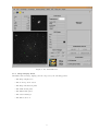
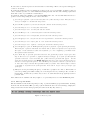
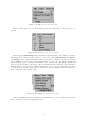
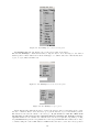
DOLORES USER MANUAL
August 28, 2009
Luca Di Fabrizio
Abstract
This is a very short introduction to the DOLORES instrument control system. Here the
user will find a brief summary of the operations needed to start up the instrument control
system as well as the main features of the interface and something else.
.
Subject:
Authors:
Last Update:
Document Name:
Instrument Users Manual
Luca Di Fabrizio
August 28, 2009
20090828QuickUserGuide.pdf
1
How to start up the system
The DOLORES instrument is essentially composed by a CCD camera and motors to put optical
elements ( Filters, Slits and Grisms ) into the optical beam. The user will interact with the whole
system by the Graphical User Interface. The Telescope Operator will start up the motors control
and the CCD controller in the afternoon. If for some reason a new start up is required please ask to
the Telescope Operator to do it. The visiting astronomer is allowed to operate only the Graphical
User Interface and The Motors Start Up Interface ( section 1.2 ). In this section I’ll describe how
to start up and shut down the system.
1.1
CCD controller
The software to operate the CCD controller runs on a Windows PC. This computer stays on a desk
in front of the door inside the ”control room”. On this desk, just in front of the door, there are 2
monitors. The leftmost one is connected, trough a switch, simultaneously to the DOLORES CCD
computer and to the SARG CCD computer. Operate on the switch to select the DOLORED CCD
computer. On the desktop of the DOLORES PC the huge ”CCD DOLORES” label is visible. A
panel named CCD ( see fig. 1 ) should be visible on the desktop and the ”led” at the right of the
”Connect” label on it should be in red ( not connected ). If this window isn’t visible it means that
the program to operate the CCD controller is not running. Start it up with a double click on the
icon ”Shortcut to CCD”. See fig. 2. Once you are sure that the CCD software is running, switch
Figure 1: CCD program control Window. Notice that the aspect is a little different when the led is red.
Figure 2: Icon to start up the CCD program control.
on the CCD controller from the Telescope Control Panel interface on the WLBUILD computer.
You will find this interface on the monitor on the right of the CCD DOLORES one, on the same
desk. To switch on the CCD controller, click the ”CCD LRS” button. See fig. 3. The led at the
right of the button will change its color from gray to green. This operation will switch ON the
controller device but will not initialize it.
1
Figure 3: Click on the red circled button to switch ON the CCD controller. The Telescope Control Panel
interface program runs on the WLBUILD computer.
1.2
The Start up GUI
Once you have switched ON the controller and after to have initialized the program to operate
the CCD controller, you will need to start the CCD and the Motors programs servers. To realize
these operations you will need to interact with the ”Dolores Motors Startup/ShutDown” GUI.
On the LRS PC desktop you will find an icon named ”Dolores Motors StartUp”. A double click
on it, will pop up the panel shown in fig. 4. This interface has a mixed functionality. First of
Figure 4: A double click on the ”Dolores Motors StartUp” icon on the LRS linux PC desktop will open
this panel. Actions to be done here are described in the text.
2
all it allows to start up ( and to shut down ) the CCD and the Motors server program. Once the
Motors server is working the user can send from this GUI some simple command to the DOLORES
motors.
This commands are:
Move the entrance slider to feed the SARG instrument. You can do that by clicking on the
”Sarg” button in the ”Select Instrument” sub-panel
Init all the DOLORES motors. It will move all the motors to calibrate the motors encoders.
The button to operate this task is on the bottom on the left.
Put the motors in the Home position. It will move all the motors to the rest position and
will switch all the lamps off
Now you are able to:
1.2.1
Start up the Motors Server
The Motors Server program is Started up and Shouted down by the buttons on the right of the
LRS Motors server label. It will activate the motors server program and it will change the ”led”
color on the right from gray to green. The label will also change from ”OFF” to ”ON”.
1.2.2
Start up the CCD server
Again on the panel described in fig. 4, press the CCD Server ”Start Up” button. Again the ”led”
will change from gray to green and the label from OFF to ON.
1.2.3
What to check?
At this point you are ready to move the DOLORES motors and to operate the CCD from the LRS
linux PC. In the afternoon, before to start your observation, remember to send an ”INIT ALL”
command. It will take some minute but will assure you to start in a clean configuration. Once
finished, if everything went fine, the label will change to green and the word INITIALIZED will
appear. If the red label ERROR appear ask the telescope operator to contact with the instrument
responsible.
1.3
Open the DOLORES GUI
The astronomer will send commands to DOLORES through the Graphical User Interface program.
To start it up, double click the ”LRS GUI” icon ( see fig. 5 ) on the LRS linux PC desktop. The
Figure 5: A double click on the ”LRS GUI” icon on the LRS linux PC will open the DOLORES GUI.
LRS GUI interface will pop up. See fig 6 in the next section. To be able to start your first image,
select the option ”SYSTEM STARTUP” under the ”LRS MANAGER” menu. Once the boot
ends open the ”SEQUENCER” under the ”EXPOSURE SETUP” panel and send a dummy bias
before to start.
1.4
Start Up check list
Inside ”Telescope Control Room” on the desk in front of the door, you will find the CCD control
computer. On this PC:
a) Check that the software to operate the controller is running.
If the panel is closed:
3
b) Open the software to work with the controller. A double click on the icon named ”Shortcut
to CCD” will do it.
c) On the WLBUILD computer, on the right of the CCD CONTROLLER Computer switch
ON the controller.
Move to the LRS computer.
d) On the Desktop you will find an icon named ”Dolores Motors StartUp”. A double click on
it will open the ”Dolores Motors StartUp/ShutDown Panel” (DMSP).
e) From the DMSP press the Start Up button to startup the LRS Motors Server. Wait until
the ”led” changes its state from OFF to ON and its color from gray to green.
f) From the DMSP press the Start Up button to startup the LRS CCD Server. Again wait
until the ”led” changes its state from OFF to ON and its color from gray to green.
g) In the afternoon remember to initialize the system. Click on the ”Init All” button. This
operation will take some minutes
h) Open the LRS GUI with a double click on the ”LRS GUI” icon
i) On the LRS GUI menu bar open the ”LRS Manager” menu. Select ”SYSTEM STARTUP”.
When the boot ends take one bias image to check that everything is working properly.
2
How to shut properly down the system
Once you have finished to work with DOLORES, please shut down the system as follows:
Close the GUI click on the Sun image marked with the label ”Bye Bye” at the GUI bottom and
the GUI program will end.
2.0.1
Stop the servers
Once you have closed the GUI came back to the ”Dolores Motors StartUp/ShutDown” panel. Here
press the button ”Home” at the bottom right of the panel. This operation will take some minutes
to switch all the calibration lamps off and to move the DOLORES wheels to the default position.
Once at the home position, press the Motors Shut Down button and the CCD Server Shut Down
button. The ”LEDs” associated to these buttons will switch from ”ON” to ”OFF” while changing
their color from green to gray. Now close the panel itself. Click on the cross at the top right of
the panel.
Now you can go to the WLBUILD computer and switch the CCD controller device off from the
TCS Panel.
2.1
Shut down check list
• On the DOLORES PC:
– from the DOLORES GUI
a) Click on the Sun image marked with the label ”Bye Bye” to close the GUI program
– On the ”Dolores Motors StartUp/ShutDown” panel
b) Press the ”Home” button and wait the time required to move the DOLORES axes to
the rest position. It, at the same time, will switch off the calibration lamps you could
have left switched on
c) Now press the two Shut Down buttons. The first will stop the motors server program,
while the second one will end the CCD Server Program.
d) Close the panel itself. Click on the cross at the top right.
• Move to the WLBUILD computer
e) Turn off the CCD controller device from the Telescope Control Panel
4
3
Graphical User Interface
The graphical user interface ( GUI hereafter ) allows the observer to interact with the instrument.
This mean to set up the instrument, check its status, start an exposure and perform a quick analisys
on the raw data.
The GUI itself is composed of two graphical interfaces. The ”Main Panel” and the ”Sequencer”.
3.1
The Main Panel
The ”Main Panel”, see Fig. 6, gives the observer the possibility to display the images, to do a
quick analisys of the raw data and to check the present instrument configuration. It is organized
in the following sub-panels:
- The top menu bar where the observer can select various functions
- The image display area
- The CCD Status panel
- The LRS Status panel
- The cursors manager
- The shut down icon
- The image timing information panel
- The GUI terminal communication panel
- The exposure setup panel
- The CCD setup panel
Each of this panel can have a setup, information or analisys functionality.
5
Figure 6: The DOLORES GUI.
3.1.1
Image Display Panel
I’ll assume that the image display panel is composed by the following panels:
- The image display area
- The zoomed portion viewer
- The image information panel
- The CCD Status panel
- The LRS Status panel
- The cursors manager
- The shut down icon
6
Figure 7: Image Display panel.
The observer will use the image display panel to see the acquired images, to send coordinates
offset to the telescope, to center the target on the slit, to perform quick data analisys, to check
the instrument configuration and to close the GUI. The most important part of this panel is the
displayed image itself. The whole acquired image is shown at the left bottom while a zoomed
portion is displayed over that on the right. Under the image there is a bar to change the image
cuts. On the left of zoom viewer there is an image information panel. The observer will read
here the displayed image name, the current cursor position and some image statistics at the cursor
position.
At the right of the image there are the remaining four panels that starting from the top are the
CCD status that sums up informations about the CCD as binning, readout mode and CCD box.
Under this panel there is the LRS Status panel that sums up the present instrument configuration.
Then there is the Cursor Manager panel that allows the user to fix two reference position on the
image. The last panel is the Bye Bye one that is only a big button to close the GUI interface.
Some special functions can be started pressing some reserved key on the keyboard or using the
mouse buttons.
The only functions activated by the mouse buttons directly on the image are the selection of the
zoomed area to be displayed and the markers set up.
7
To select the zoomed area press once the left button on the image. The zoomed portion will appear
on the zoom viewer.
To define the marker position by fitting the position of an object ( something on which a centroid
can be calculated ) select one of the markers activating its button in the cursor manager panel and
then click on the object with the central button.
Special keys defined are similar to the imexam IRAF task ones. To use this functions select a
position on the image using the mouse cursor and then:
j press the j to perform a gaussian fit along the rows of the selected position. This function is
used, for example, to calculate the slit position
k press the k to perform a gaussian fit along the columns in the selected position
l press the l key to see a cut along the selected line
c press the c key to see a cut along the selected column
h press the h key to see a counts histogram around the selected position
r press the r key to see a radial profile gaussian fit in the selected position
g press the g key to see a 2d gaussian fit, and its parameters, around the selected position
s press the s key to see a surface plot in a box around the selected position
e press the e key to see a isophotic contour plot around the selected position
p press the p key to open an IRAF phot like program to perform a quick aperture photometry.
This will open a panel on which the user will be able to define an aperture and a sky around
the object. A raw estimation of the star magnitude ( as −2.5 × log(F lux) ) and Flux inside
the aperture will be retrieved
x press the x key to open the spectrum extraction and quick-look program. If you press this
key on the trace of a spectrum a graphical interface will pops up to guide you through the
spectrum extraction. Once ended the plot of the extracted spectrum will appear. On the
extracted spectrum window some IRAF splot like key are active: Press the a key twice to
retrieve a zoomed spectrum portion. Press the k key on a feature to retrieve a gaussian fit on
it. Press the e key to retrieve the equivalent width of a feature. Press the s,r key to retrieve
a smoothed or original version of the spectrum. Press the = key to save a postscript copy
of the plot
q Always close the plots using the q key or with the top right cross. Due to IDL feature if
you leave pending plots while reading out or moving the motors you will produce a crash of
the interface. In this case you have only to shoot it down and start it up again (section 1.4
points h and i
More functions are available but they require to be previously selected on the menu bar panel.
3.1.2
The top bar menu
The user will find on the menu bar panel ( see Fig. 8 ) various utilities grouped under lists. Starting
from the left the list named file ( see Fig. 9 )from which the user can load an image, display the
image header and exit the GUI program ( the same as the Bye Bye button ).
Figure 8: Menu bar panel.
8
Figure 9: The file list on the menu bar panel.
The second list is the color one from which the user can change the color image palette. See
Fig. 10
Figure 10: The color list on the menu bar panel.
The subsequent LRS Manager list only has the ”System Startup” entry. This is to start up
the system after opening the GUI program ( see section 1.3 ). The CCD Manager and Telemetry manager lists contains maintainance functions and have no utility for the user. Under the
next, Utilities the user will find various useful utilities. See Fig. 11. The Display AZ/EL axis
will plot the projection of elevation and Azimut on the current image, The display compass will
show the North and East on the image. The clear markers function will delete all the displayed
markers while the save and retrieve markers will allow the user to save the defined makers position
on a file and to load them. Is strongly recommended to save the markers positions because they
will be lost in the case of a GUI crash.
Figure 11: The Utility list on the menu bar panel.
Under the Zoom list the user will find some useful function to rotate and flip the image axis.
The zoom function itself is not implemented yet.
9
Figure 12: The Utility list on the menu bar panel.
The Display slit will only display a plot of the selected slit on the image.
The last list, Analisys, contain various entry to help the user to move the target to the desired
marker position. These functions needs the maker(s) to be defined and active. The list has the 1
object, 2 object, MOS and M2 focus.
Figure 13: The Analisys list on the menu bar panel.
Figure 14: The Analisys 1 object option.
The 1 object entry will help the user to retrieve the target position on the image and to calculate the coordinates offset to move the telescope to put the selected object on the marker position.
The functions can send the offsets to the telescope. If you decide to send the offset from
the interface to the telescope the autoguide must be switched off. Ask the telescope
operator if it’s so. To calculate the offset the user can chose trough three algorithm, ( see Fig
14 ), Gauss Fit will perform a 2d gaussian fit on the target, Centroid will calculate the x and y
coordinate using the centroid IDL function, Cursor allow the user to select the x and y position
10
with the cursor.
To use these functions the user needs to select the object with the mouse. In detail the operations
to use these functions are:
Gauss fit Select one of the marker. Select the function that you want to use from the drop list, move
the cursor on the image, select the target position with the left mouse button, select the
object to be fitted with the right mouse button. This last operation can be done on the zoom
viewer. An orange window with the calculated offsets will pop up asking if you want to send
the offsets to the telescope. If you answer yes, please before tell to the telescope operator that
you are sending coordinates offset. Remember that the autoguide must be inactive in this
case. If you want to send the offsets while auto-guiding tell them to the telescope operator
and answer ”NO” on the window
Centroid Select one of the marker. Select this function from the drop list. Select a zoomed area around
your target with the left mouse button. Select the object for which you want to calculate the
centroid with the right button. You can do this operation on the zoomed portion or directly
on the image. An orange pop up will rise suggesting RA and DEC offsets to be send to the
telescope to move the target to the selected marker. If the autoguide is not active you can
send the offset directly to the tracking by answering yes. Otherwise tell this offsets to the
telescope operator and he will apply them for you.
Cursor Select one of the marker. Select this option from the drop list. Mark the area around the
selected target with the left button. Select the pixel of the target that you want to move
over the marker with a right button click on the zoomed portion.
Consider that gaussfit is a good choice for target not saturated and with a good S/N. Centroid
can still work on not strongly saturated targets. Cursor is the only chance to center really faint or
badly saturated object.
3.1.3
The image timing information
This panel is an information utility. On it will appear the status of the actual image. If an exposure
is active a count down clock will appear to inform about the remaining exposure time. If the image
is in read out status a chronometer will appear. When no exposure is active the DONE label is
present.
3.1.4
The GUI terminal communication panel
On this panel will appear the command send to the CCD controller and to the motors and some
message.
3.1.5
The exposure setup panel
The exposure setup panel is composed by 4 button. The sequencer button opens the sequencer
GUI ( see below ). The ABORT button will abort the ongoing exposure, no image is returned.
The STOP button will end the ongoing exposure. The actual image is read out and saved. The
extend function allow to extend the actual image exposure time. The EXTEND function is in
test phase. If you extend the actual image just when the read out begin the GUI will
crash and you will need to close and reopen it
3.1.6
The CCD setup panel
The CCD setup panel allow to select the binning and read out mode. At the moment the CCD
can be read only with the Left read out option.
3.2
The Sequencer
The ”Sequencer” allows the observer to set up and to start a single exposure or a series of them.
The sequencer is shown in Fig. 15.
11
Figure 15: The Sequencer GUI.
Up, on the left ( see Fig. 15) you will find a list of programs names. Please remember
to select the correct program name each time you open the sequencer. You will be
allowed to retrieve only the images of your program from the archive. In case you forget
to set your correct program name remember to send an e-mail to your contact astronomer and to
[email protected].
The Sequencer is organized in row. Each row is a blueprint of an image to be started.
Each row is organized in fields that from the left to the right are:
Active The Active field is a button to activate a row
Expo Type Is a drop list where you have to select which kind of exposure you want to start. You can
select trough science,calib, flat, bias or dark
Cycle You can reapet the same image more than once. When you reuse the same exposure configuration no check is done on the instrument axes. So it takes less time than activating more
row with the same configuration.
Exptime Here you decide how many seconds you will expose.
Slit Here you can choose to do photometry, in which case you choose the beam position, or
spectroscopy with one of the five possible long slit or Multi Object spectrometry selecting a
MOS Mask
Filter If you are doing photometry you can select a filter here. Filters coupled with a grisms as
blocking orders don’t need to be selected. They will be inserted automatically.
Lamp If you selected Calib as image type you are allowed to switch ON one of the lamp set
described under this drop list.
Xdown Xup If you are interested in boxing the CCD select the starting X as Xdown and the ending X as
Xup
Ydown Yup If you are interested in boxing the CCD select the starting Y as Ydown and the ending Y as
Yup
12
Arch If you want to save this image remember to press this button. Image not archived will not
be sent to the Archive. In any case they will be saved locally. If you forget to activate this
button send an e-mail to your contact astronomer and to [email protected]
The observer can decide to activate only one row or more of them.
At the Sequencer bottom there are four buttons. START will begin to execute the selected row
from the top to the bottom. Once started it’s still possible to modify a sequencer row not started
yet. The SAVE button allows the observer to save the sequencer configuration for further use.
LOAD button allow the user to charge a saved sequencer. The RESET button sets all the rows
to the default configuration. DONE will close the Sequencer.
4
Observation hints
4.1
General operations
Before starting you will need to do some general operations.
4.1.1
Pointing
This operation will be made by the telescope operator. It’s to reduce the pointing error so will help
you to recognize your fields and to center your objects inside the slit. Ask the telescope operator
to do it as soon as possible before observing.
4.1.2
Focusing
The telescope has a program to calculate the focus variation as function of the temperature and
elevation variation. The telescope operator will adjust the focus for you. Anyway remember to ask
occasionally the telescope operator to check the focus while reading out the current image. For
the focus program to work properly you will need anyway to set the focus zero-point. In theory
once a night should be sufficient. In practice you could have to repeat it during the night if the
wheater parameters ( temperature, improved seeing, ... ) changes. To do the focus take a 20-30
seconds ( take exposures longer than 10 seconds anyway to avoid the seeing variability ) of a not
crowded field. Take this image without photometric filters and inserting the pyramid sensor (
grisms drop-list on the sequencer ). The pyramid will split each spot into 5 spots in your image.
Use the M2 focus from the GUI top bar menu under Analisys and follow the instructions.
Eventually repeat to check.
4.1.3
Sky flats and standard stars
If you take sky-flats or standard stars during your observation it would be useful for the TNG users
if you remember to switch the program name to CALIB. This is true for afternoon calibration
too. If you do so the calibration images you take will be avaible to the TNG user community
imediatelly. Remember to select your program name before to start your program. If you forget to
do that warn up your support astronomer and the software team ( [email protected] ) or your scientific
images will be public too. On the tracking computer are available coordinates catalog for the most
used photometric and spectrophotometric standard star as blank fields for flat fielding. In the web
page you will find links to useful standard star catalogs.
4.1.4
Targets catalog
A User Target Catalog in the format readable by the telescope tracking computer is recommended
and welcome. This must be an ASCII file which name is given by the observing period an underscore
the tac, cat, itp identifier the program number and a .cat extension. If, for example, you are
observing the program TAC13 during AOT19 your User Target Catalog should be named as
aot19 tac13.cat. The first line must be left blank or include a fields descriptor line. Each line will
describe one object name and coordinates. Each line has 9 fields separated by SPACES. Fields
are:
ASCII name
descriptor
Right ascension
declination
Equinox
RA proper
Motion as ”/year
DEC proper
Motion as ”/year
parallax
Radial
Velocity
EPOCH
NAME
M71
M15
RA
19:53:42.020
21:29:56.290
DEC
18:46:42.14
12:10:00.45
EQX
2000.00
2000.00
MPRA
0.001
0.0
MPDEC
0.002
0.0
PAR
0.0
0.0
RV
0.0
0.0
EPOCH
2000.00
2000.00
13
4.1.5
Position Angle
If you need a position angle different by the standard one tell it to the telescope operator during
the pointig. It will avoid the overhead time taken by the derotator to reach the final position.
14
Contents
1 How to start up the system
1
1.1
CCD controller . . . . . . . . . . . . . . . . . . . . . . . . . . . . . .
1
1.2
The Start up GUI . . . . . . . . . . . . . . . . . . . . . . . . . . . . .
2
1.2.1
Start up the Motors Server . . . . . . . . . . . . . . . . . . . .
3
1.2.2
Start up the CCD server . . . . . . . . . . . . . . . . . . . . .
3
1.2.3
What to check? . . . . . . . . . . . . . . . . . . . . . . . . . .
3
1.3
Open the DOLORES GUI . . . . . . . . . . . . . . . . . . . . . . . .
3
1.4
Start Up check list . . . . . . . . . . . . . . . . . . . . . . . . . . . .
3
2 How to shut properly down the system
2.0.1
2.1
Stop the servers . . . . . . . . . . . . . . . . . . . . . . . . . .
4
Shut down check list . . . . . . . . . . . . . . . . . . . . . . . . . . .
4
3 Graphical User Interface
3.1
3.2
5
The Main Panel . . . . . . . . . . . . . . . . . . . . . . . . . . . . . .
5
3.1.1
Image Display Panel . . . . . . . . . . . . . . . . . . . . . . .
6
3.1.2
The top bar menu . . . . . . . . . . . . . . . . . . . . . . . . .
8
3.1.3
The image timing information . . . . . . . . . . . . . . . . . . 11
3.1.4
The GUI terminal communication panel . . . . . . . . . . . . 11
3.1.5
The exposure setup panel . . . . . . . . . . . . . . . . . . . . 11
3.1.6
The CCD setup panel . . . . . . . . . . . . . . . . . . . . . . 11
The Sequencer . . . . . . . . . . . . . . . . . . . . . . . . . . . . . . . 11
4 Observation hints
4.1
4
13
General operations . . . . . . . . . . . . . . . . . . . . . . . . . . . . 13
4.1.1
Pointing . . . . . . . . . . . . . . . . . . . . . . . . . . . . . . 13
4.1.2
Focusing . . . . . . . . . . . . . . . . . . . . . . . . . . . . . . 13
4.1.3
Sky flats and standard stars . . . . . . . . . . . . . . . . . . . 13
4.1.4
Targets catalog . . . . . . . . . . . . . . . . . . . . . . . . . . 13
4.1.5
Position Angle
. . . . . . . . . . . . . . . . . . . . . . . . . . 14
i