1
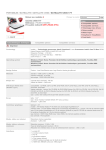
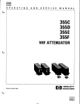
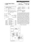
NOOEL 241
CONTESTS
CONTENTS
7
section
Page
SpEi-IF*C*TIi)NS
____________--_---_-----------------------
1.
GESE&AJ DESCRIPT~OA----------------------------------------
1
2.
OPERATIOS--------------------------------------------------
3
3.
CIRCUIT
4.
MAINTENANCE------------------------------------------------
6
5.
REPMCEI\BLE PARTS------------------------------------------
7
~ESCR~pT~ON----------------------------------------
SCHEMATIC--------------------------------------------------
0472
ii
4
15
i
SPECIFICATIONS
MODEL 241
.
SPEClFlCATlONS
OUTPUT:
Voltage 0 to 1OW vdfs de in 0.01~volt steps.
Current: 20 milliamperes dc maximum.
Polrrlly:
Posiiive or negative.
Floaling: WI volts maximum ofi chassis ground.
ACCURACY: aO.05gk of dial setting or 4 millivolt. whichever iS
greater.
RESOLUTION: A “Trim”
potentiometer
permits interpolation
between sleps with a resolution of betler than 1W microvoI1s.
TEMPERATURk COEFFICIENT OF REFERENCE: &lo Ppm/T.
LINE RLGULATION: *O.WS% or 1 millivolt for 10% line change.
LOAD REGULATION: ~O.OOSqb,rom”o,oad
tofull bad.
RIPPLE AND NOISE: Less than 1 millivolt rms above 5 cps.
OUTPUT IMPEDANCE: Less than 0.05 ohm at dc.
RECOVERY TIME: No load to full load. less than 1 second lo
OVERLOAD PROTECTION: Ovtwt
is disconnected
within 50
millisecondsif
currsn~axseedi.pploximately24
milliamperes.
CONNECTORS: Output: Tefkninrulated
UHF type.
POWER: 105.125 or210.250 VD,~S.60.60 cps. IOS watts.
DIMENSIONS. WEIGHT:l’high
x Wwidsx12’deep;
netweight.
25 pounds.
ACCESSORIES SUPPLIED: Mating co”“estors.
ACCESSORIES AVAILABLE:
Model 1491 End Frames:
adapts Model 241 for bench “se
ii
0372
MODEL 241
GENERAL DESCRIPTIOS
SECTION
1.
GENERAL
to dc
GENERAL. The Model 241 is the successor
l-l.
secondary standards
that employ mechanical
choppers
If offers
freedom from adjustment
and standard
cells.
and calibration,
long term stability
LO voltage
or
temperature
variations,
and immunity to shock and vibration.
The 241 complements the popular Keithley
greater accuracy,
regulation,
240 Supply. offering
current
output and floating
operation.
APPLICATIONS.
Include
calibrati.”
of meters,
1-2.
transducers,
and paver supplies:
testing
insulation,
diode, and capacitor
leakage resistances;
measuring
dc amplifier
gain. linearity,
drift
and common mode
It can also be used as a voltage
comparator,
EjeCtiO”.
voltsge
reference
for analog camputors,
and excitation
potential
for photo-cells
and ion chambers.
1-3.
FEATURES.
of 0.005% per hour is gained
8. Extreme stability
by using,
as a reference
standard,
a highly
stable
zener diode with a” ambient temperature
coefficient
of less than 0.001% per degree C. 1t is unaffected
by rough handling
or shock and cannot be damSed in
The cmparat”r
device is a Keifhleyordinary
use.
designed photo chopper of indefinite
life,
havi”8 “a
0472
moving
DESCRIPTION
parts
and requiring
no maintenance.
b. High output accuracy within
0.05% is assured
through the “se of encapsulated
wire-wound
resistors
with 0.02% divider
accuracy.
C. From O-1000 volts at up to 20 milliamperes
plus, minus or floating
- ca” be dialed
in 100, 10, 1.
0.1 and 0.01 volt steps with 5 calibrated
panel
switches.
“TRIM” potentiometer
permits
interpolation
between steps with B reeolutia”
of better
than 100
microvolts.
d. Noise and hum are belw
1 millivolt
line transients
- excellent
line regulation
241 ideal for capacitor
and diode testing.
bration.
nos.
Lo”
- make the
meter cali-
e. Overload protection
is accomplished
by a fastacting
relay circuit
which disconnects
the output witbin 50 milliseconds
at about 24 milliamperes.
A “RESET”
front panel button reatores
operation.
f.
Other features
include
“STAM)BY” which removes
voltage
from the output,
making possible
connections
while the instrument
is operating;
bench or rack operation.
GENERAL DESCRIPTION
MODEL 241
Front
I
TABLE l-l.
Panel Controls
Control
Functional
OUTPUT Switch Sl
OUTPUT VOLTS
s3
S4
S5
S6
s7
CALIBRATE Control It109
RESET Switch SZ
OVERLOAD Indiearor
DS-3
Power Indicator
US-1
READY Indicator
DS-2
TRIM Control P.151
sets 0"Lp"t
on.
Sets output
in 1oov increments.
READY
CALIBRATE
INDICATOR CONTROL
DSZ
RI09
I
sees oucpu’t in IOV increments.
sets OUtpUt in 1v increments.
sets OUrpUt in O.lV increments.
sets O”CP”L in p.01v increments.
Adjusts
output calibration.
Overload reset control.
Indicates
overlo&
condition.
Indicates
parer on.
Indicates
ready condition.
kdjuata
output up to 15 mV.
POWER OUTPUT
TRIM
CONTROL INDICATOR SWITCH
Sl
DS1
R151(SS)
FIGURE 2.
2
Description
Front
RESET
SWITCH
s2
OVERLOAD
INDICATOR
DS3
Panel
0472
WDEL 241
SECTION
(2t
2-1.
OPERATIOS
2.
OPER4TING CONTROLS.
The five skirted
dials ecrose
8. output volts.
the panel permit setting
the voltage
directly
from
zero to 1000 volts with en accuracy of 0.05% or 1
millivolt
end e resolution
to 10 millivolts.
Extrapolation
between 10 millivolt
eetb. Trim.
tinge is possible
with the TRIM control
which Is beThe TRIM control
should be
low the wltage
dials.
net to the OFF position
when not in use to avoid inBCCUrate o"tp"t.
C. Calibrate.
The calibration
Potentiometer
is
available
from the front panel and is covered with en
acorn nut to prevent
inadvertent
operation.
The instrumenr is set to well within
0.05% accuracy et the
factory.
However, since the linearity
of the output
is within
0.02%, if the user he8 a potentiometer
of
thie accuracy
available,
it is possible
to see the
calibration
more closely
for specific
needs.
This
control,
however, should not be touched unless proper
calibration
facilities
ere available.
Bee mainten*nce section).
d. Power Off - Standby - Output On. This switch
turns on the power, places the instrument
in STANDBY
ower on but potential
disconnected
from the outp"t
minals),
and turns on the output terminals.
2-2.
CONNECTIONS, POLARITY AND FLOATING OPERATION.
The output connectors
ere located
et the rear of the
Two output connectore
ere used, ‘x,e for
instrument.
the positive
and one for the negative
line.
A sharting cap ie provided
so that either
the positive
or
negative
Line may be grounded to the cese.
Thus, if
the shorting
cap grounds the negative
line,
the remining
cmmecror
has its center terminal
at plus pclarity,
end the negative
terminal
is on the shell
of
0472
OPERATION
the connector.
If the shell grounds the other connector,
the oppoeite
holds true.
Floating
operation
is permiesible
provided
that potential
of either
line
to the cede doe8 not exceed 1500 volts.
For floating
operation,
remove the ehorting
cap and use two aeparate coaxial
cables,
one for plus end one, for minus.
Due to the high potentials
the ueer is cautioned
to
"se connectors
end shielded
coaxial
cable only.
2-3.
PRELIMINARY OPERATING PROCEDURE.
The Model
241 Regulated
High-Voltage
Supply is shipped complete
with tubes and fuses and is accurately
calibrated
at
the factory.
Plug the power cord into a source of
proper voltage
and frequency.
Unless otherwise
specified,
the unit is wired for 117V. 50 to 60 cps.
For
220 volt operation
change the jumpers on the tre,,sformer primary
ae indicated
in the schematic diagram.
After
the connections
have bee,, made, turn inetrument
to STANDBY. The pilot
light
will
go on but the READY
light
will
be delayed by the internal
time-delay
relay for 30 seconds.
After rhie time, the READY light
will
go on, end the instrument
is ready to operate.
If the instrument
is immediately
turned to the ON
position,
the OVERLOAD light
will
go on with the READY
Light,
and it will
be necessary to operete the RESET
button
to make voltage
appear et the output terminals.
If the current
rating
of the
2-4.
OVERLOAD CIRCUIT.
supply is exceeded by more than approximately
4 milli'
amperes, the overload
circuit
will
disconnect
the output in about 50 milliseconds
turning
on the red OVERLOAD light.
To restore
operation
press RESET button.
If the OVERLOAD light
refuses
to go out, or the relay
charters
when the reeee button is pushed, either
the
supply has become defective
or the overload
is still
present.
DO NOT PRESS RESET BUTTON MORE THAN MOMENTARILY TO AVOID DAMAGE TO POWERSUPPLY.
3
CIRCUIT DESCRIPTION
MODEL 241
SECTION
3.
CIRCUIT
DESCRIPTION
0
i
3-L.
GENERAL,. In Figure 3, two cascaded electronic
series regulators
furnish
e high degree of load end
Line regulation.
The first
regulator
reduces the effect of input voltage
change while the second eegulator
provides
e means for varying
the output voltege.
It provides
e Low output impedance,
end very close reReeis,toee Rl end R2 compere the output voltgulation.
age against
e silicon
voltage
etsnderd.
By varying
Bl the voltage
may be msde to essume eny voltage
between zero end 1000.
The current
supply to the reference Is doubly regulated.
Relays RYl end RY2 ere
overload
protectors
and RY3 end RY4 provide a 30-secand time delay on turn on.
3-2.
DETAILED CIRCUIT DESCRIPTION.
8. Refer to,DR L3333D at the rear of thle manual.
The high voltage
output of the transformer.
Tl is
rectified
and supplied
to the plste of V2, the series
tube in the pre-regulator.
V4 compares a fraction
of
the pee-regulated
volcege
from the divider
network
R127. to R129 and R131 to the 150 volts of V6. This
regulator
supplies
approximately
1200 volte to the
final
regulator.
b. The
amplifier
stabilizing
(Keithley
ma+Lstor
final
regulator
consists
of series tube V3,
V5 difference
amplifier
VU,
end B drift
amplifier
consisting
of light
modulatora
15101, a two stege amplifier
VlO, and deD13 to D16.
C. A very stable
9 volt potential
is obteined
st
point 29 from the zener reference
standard.
The zener
element is operated et ite rated current
end obtains
this curreat
regulated
to better
than 1% from the casceded VR tubea V7, VS. end V9.
To accomplish
this,
RI11 is provided
to adjust
the rated current
through
the zener, the link beween points
27 end 28 is removed
and e 1/4X toler&ce
10 ohm resistor
is put at this
With an accurate
voltmeter,
Rlll
is adjusted
point.
until
the voltage
scross the 10 ohm reeistor
correeponds to the product of rated current
x 10 ohms.
d. The voltage
from the zener is compared against
the output voltage
by means of RlOS, RL09, end RllO
(these resistors
correspond
tp Rl of Figure 1).
Since
the ection of the feedback amplifier
is to maintain
point
35 exactly
et ground; resistors
RLOS through RllO
ere adjusted
so that exactly
1 milliempere
of current
flows into point 35 from the zener.
This current must
now flow into R151 end through R153 to R182. Since
these reeietore
ere connected between point 35, which
the feedbeck meintsins
at ground end the high voltage,
the output voltage
must aeeume a value of 1 milliampere
times the value of resistance
chosen by the voltage
dials
which select
resistors
RI51 and R153 through
RLS2. It is so arranged that the output voltage
equals
one volt per thousand ohms connected between point 35
end ground.
e. The remainder
of the circuit
is e high gain
feedback amplifier.
Point 35, es mentioned
above,
meinteined
et ground by the feedback action.
This
occurs because of the following:
is
1. If point 35 is not et ground, the light
modulator
convert8
the voltage
iato en ec signal
which
is amplified
by the two sections
bf VlO.
The eignel is then demoduleted
by synchronous
demodulator
D13-D16.
The resultant
dc signal
is filtered
by
R147 end Cl24 and applied
to pin 7 of Vll.
The signal is further
amplified
by VL1 end V5 end applied
to the control
grid of V3. The signal
will
be of
such polarity
as to return
point 35 to exactly
zero
volts.
At frequencies
higher
then e few cycles,
VlO and the essociated
modulator
are not operative
end in such e ceee the error signa& proceeds directly
to pin 2 of VLl end by-passes
the modulator.
CL3D
by-psssee
the comparison divider
end increases
the
signal
et high frequencies,
which peeees into pin 2
of vu.
2. Several safeguards
are incorporated
into
the
circuit
et this point.
012 end RLO-7 ere connected
between ground and the summing node, point 35. D12
is e silicon
diode which is normally
open but conducts if the euraning point is carried
more then 0.7
volt positive
due to e transiene.
This protects
the
voltage
reference
diode.
RYL is the overload
re$
f
It is shunted by R136 to eet its pull in sensitiv
et approximetely
24 milliamperes.
When en overload
occure end RYL does pull in, it breaks the selfholding
contact
on RY2 causing it to open.
To reetore operation,
RESET switch SW2 is pushed to momentarily
reclose
the RY2 self-locking
circuit.
The
OFF, STAND BY, WTPUT ON switch,
SWL, also operates
RYZ opening it In the STANDBY position
by interrupting the holding
circuit
ot RY2 by means of its first
deck between points
25 end 38. SW1 re-energizes
RY2
in the OUTPUT ON position.
RY4 is a 30-second
therme1 time-delay
which ie recycled
by RY3. If RY3 is
not energized,
RY2 cannot close,
end the circuit
remains in the overload
or standby position.
3. After
the signs1 is amplified
by Vll.
it is
to
further
amplified
by V5. This tube ia srrenged
eupply driving
voltage
to V3 eo that the supply ten
cover a range of 0 to 1000 volts.
To do this the
place supply must vary over a range of about minue
50 to plus 950 volts.
Therefore,
the cathode of V5
is returned
to minus LO5 volts.
The screen of V3 is
supplied
with e floating
105 volts bootstrapped
to
the cathode of V3.
In this way a conetent
ecreen-tOcathode voltage
is maintained,
end the tube operates
es a pentade.
The advantage of this connection
la
that much less grid swing is required
over the op,eratina
range. and the ac plate impedance of V2 is
markedly
increased.
This results
in e higher
degree
of output isolation
from input transients.
8
4
0472
CIRCUIT DESCRIPTION
MODEL 241
+
PUT
“OLT,’
L---&,&&d- -105
HI
:EIYHLEY
“kr
I’
*
FIGURE 3.
0472
Simplified
Circuit
‘v!
Diagram.
5
.
MAINTENANCE
MODE. 24,
SECTION
4.
CAUTION
Be extremely
careful
that the regulated
power
supply is disconnected
from the power line when
unscrewing
the tap or bottom covers.
Many cirwit
components are 1000 volts or more above
ground.
When the circuit
is on negative
polarity,
the minus side of the circuit
is 1000 volts below ground.
Therefore,
do not ass"me it is safe
to touch any part of the circuit
when the parer
is on.
TUBE REPLACWENT. Tube replacement
is non-critHowever, Ampere type ECC B3/12AK7 Is recorrnended for VlO and Vll.
MAINTENANCE
voltage
at the plate of V2.
It should be about 1700
If it is not this voltage
plus or minus 202,
volts.
check the input rectifiers
and filter
capacitor.
2. If this point checks, next check the voltage
et the cathode of V2. This should be about 1203
If it is much lower,
either
V2, V4 or pcsYOlCS.
sibly V6 is defective.
If changing these tubes does
nor correct
the difficulty,
measure the voltage
at
pin 5 of V4. If the voltage
is about 150 but the
voltage
ac pin 3 of V2 is still
incorrect,
either
R127, R12S. R129 or R131 may be defective.
4-1.
ical.
ZENER REFERENCE. This element should not require
replacement.
If, however, it is necessary,
first
remove test jack jumper at poinr 28 end 27.
Insert
a
114% 10 ohm resistor,
and adjust Rlll
until
the voltage ecross the resistor
is exactly
the product of
rated current
rimes resistance.
The", measure the
voltage
s.cross the reference.
Since the tolerance
of
the zener elements is 8.45 t" 9.45 volts,
RllO is selected so that the sum of RlOB, R109 (set at half value
equal ea 50 ohms) and RllO equals in K ohms the voltage
as closely
as possible.
Therefore,
if the reference
is changed, RllO will
have to be changed.
4-2.
It is recommended that the caliRECALIBRATION.
4-3.
bration
be adjusted
initially
at 500 volts
curp"t
and
then checked at several
voltages
above and below this
point.
The equipment used at the factory
is a Leeds
and Northrup
Type K3 Potentiometer,
and a Model 7592-S
Volt BOX. This equipment has a range of 0 to 1500
volts
and a" 0.035% limit
of error.
general procedure
TROUBLESHOOTING. The f,,llawing
is recommended:
CAUTION: "HEN TROUBLESHOOTING, TURN
VOLTS DIALS TO MAXIMUM READING:
4-4.
1.
which
6
NO output:
With extreme care
will
read at least 2100 volts
and a voltmeter
dc, measure the
3.
If the voltage
is correct
up to here but 5.r
not correct
at the output,
ground pin 7, "11.
If
approximately
the correct
voltage
is not obtained
at
the outpue, the trouble
is in the modulator
cirxtit.
The tube and the other components of that circcit
should be checked.
4.
If the modulator
is not at fault,
tubes in the remainder
of the circuit.
NOT CHANGE TUBES "ITS POWERON.
Cry changing
CAUTIOX: DO
5. If this does not eliminate
the fault,
check
the standard resiscar
string
far a" .,pe" circuir,
and check the ze"er diode for the correct
voltaje.
6. Finally,
if the cause is still
not discovered,
"ifh
the voltage
dials
at their maximum setting.
connect a voltage
source Of low internal
impedace
at point 35.
Effectively,
this shorts out the feedback.
If the instrument
is ope:~tional,
a smalL
variaeian
in this voltage
will
drive the output full
scale (zero to 1000 volts).
Since there is a d+feet in the system. the signal
will
not affect
the
outpllt.
However, by measuring
the plate and grtd
potentials
progressively
along the circuit,
the
point can be found where no signal
is being trwmitted.
In this way the defective
component caa be
located.
Periodically
burnish
noise and increased
NOTE
relay contacts
stability.
for
lover
0472
REPLACMLE
MODEL 241
SECTION
REPLACEABLE
5.
REPLACEABLE PARTS LIST:
This section
contains
a list
of components used in this instrument
for
wee reference.
The Replaceable
Parts List describes
the Individual
parts giving
Circuit
Designation.
Description,
Suggested >lanufacturer
(Code Number),
5-1.
PARTS
PARTS
Manufacturer's
Part Number, and the Ksithley
Pert
Number.
Also included
is a Figure Reference
Number
where applicable.
The complete name and address of
each Manufacturer
is listed
in the CODE-TO-NAME
Listing
following
the parts list.
TABLE 5-1.
Abbreviations
end Symbols
A
ampere
CbVar
Cl?dl
Cer Trimer
camp
Carbon Variable
ceramic Disc
Ceramic Trimmer
composition
DCb
fksig.
Deposited
Carbon
Designation
F
Fis
farad
Figure
GCb
Class
enclosed
k
kilo(l0
3,
micro
(10-6)
Mfr.
MtF
MY
Meg (106)
Manufacturer
Metal Film
Mylar
NO.
Number
M
F.&A
ETB
ETT
ElecCralytic,
Electrolytic,
Electrolytic,
Aluminum
tubular
tantalum
5-2.
ELECTRICAL SCHPIATICS AND DIAGRAMS. Schematics
end diagrams are included
LO describe
the electrical
circuits
es discussed
in Section 3.
5-3.
HOW TO "SE THE REPLACEABLE PARTS LIST.
This
Parts List is arranged such that the individual
types
of camponents are listed
in alphabetical
order.
Main
Chassis parts are listed
followed by printed
circuit
boards and other subassemblies.
5-4.
HOWTO ORDER PARTS.
8.
Sales
Replaceable
parts may be ordered through
Service
Department,
Keithley
Instrumerxs,
0472
the
Inc.
or your
nearest
Carbon
ohm
FC
Poly
pica (10-12)
Printed
Circuit
Polystyrene
Ref.
Reference
TCu
Tinner
"
volt
"
ww
WV*=
watt
Wirewound
Wirewound
Keithley
b. When ordering
information.
1.
2.
3.
4.
5.
R
parts,
Copperweld
Varieblf
representative.
include
the following
Instrument
Model Number.
Instrument
Serial Number.
Part Description.
Schematic Circuit
Designation.
Keithley
Part Number.
C. All parts listed
are maintained
in Keithley
Spare Parts Stock.
Any pert not listed
ten be made
Pert6 identified
by the
available
upon request.
Keithley
Manufacturing
Code Number 80164 should be
ordered directly
from Kelthley
Instruments,
Inc.
7
REPLACEABLE PARTS
MODEL 241 VOLTAGE SUPPLY
MODEL 241 REPLACEABLEPARTS LIST
CAPACLTORS
Circuit
Desig.
Value
Type
Mfg.
Code
Mfg.
Part No.
Keithley
Part No.
Cl01
Cl02
Cl03
Cl04
Cl05
.00047
.00047
20 pf
.00047
.00047
pf
pf
IJ.f
pf
1000 v
1000 v
450 v
1000 "
1000 "
CerD
CerD
EMC
CarD
CerD
71590
71590
56289
71590
71590
DD-471
DD-471
TVLl714
DD-471
DD-471
C64-470P
C64-470P
C33-20M
C64-47OP
C64-470P
Cl06
cm7
Cl08
Cl09
Cl10
.00047
.00047
.00047
.00047
.00047
pf
pf
vf
Ilf
pf
1000
1000
1000
1000
1000
CerD
Ce?ZD
CerD
CerD
CerD
71590
71590
71590
71590
71590
DD-471
DD-471
DD-471
DD-471
DD-471
C64-470P
C64-470P
C64-470P
C64-470P
C64-470P
Cl11
Cl12
Cl13
Cl14
C115A
C115B
2.0 vf
.00047 pf
.00047 pf
16 pf
20 pf
20 pf
3000 v
1000 "
1000 "
600 v
350 "
350 "
MY
CerD
CerD
EMC
ETB
ETB
99120
71590
71590
14655
12674
12674
LK30-205
DD-471
DD-471
KR616C
ME50415
ME50415
c53-2M
C64-470P
C64-470P
C34-16M
C52-20M
C52-20M
Cl16
Cl17
Cl18
Cl19
Cl20
.02 pf
.02 pf
.07. pf
.1 )If
.Ol I*f
1000 v
1000 v
1000 "
200 "
1000 "
CerD
CerD
CerD
MY
CerD
72982
72982
72982
13050
72982
84125V203P
84125V203P
84125V203P
SMlA
81125V103P
C22-.02M
c22-.02M
C22-.02M
C47-.lM
C2.!-.OlM
Cl21
Cl22
Cl23
Cl24
Cl25
1 Pf
1 I-rf
.l pf
1 Clf
.0068 pf
200 "
200 "
200 v
200 "
1000 "
MY
MY
MY
MY
CerD
13050
13050
02777
13050
72982
107-21
107-21
P-12M
107-21
811Z5V682P
C66-1M
C66-LM
C66-.lM
C66-1M
C22-.0068M
Cl26
Cl27
Cl28
Cl29
Cl30
.033 pf
.02 pf
.OOl wf
1.0 pf
.47 pf
1600 v
1000 "
1000 "
400 "
1000 "
MY
CerD
CerD
MY
MY
14655
72982
72982
99515
99515
MGT-S33
841Z5V203P
8OlZ5V102P
E4-105
EP-32462
C43-.033M
C22-.02M
C22-.OOlM
C73-LM
C54-.47M
Cl31
Cl32
Cl50
.47 pf
a.033 pf
.005 pf
value, factory
1000 "
1600 v
6000 v
MY
MY
MY
99515
14655
14655
EP32462
MGT-S33
PKJ16OD5
C54-.47M
c43-.033)1X
c130-.005PI
*Nominal
8
Rating
"
"
"
"
v
set.
0472
MODEL 241
REPLACEABLEPARTS
DIODES
Circuit
Desig.
Mfr.
Code
Mfr.
Part
Type
Dl
D2
D3
D4
D5
Silicon
Silicon
Silicon
Silicon
Silicon
02735
02735
lN3252
lN3252
lN3252
lN3252
lN3252
RF-17
RF-17
RF-17
RF-17
RF-17
D6
D8
D9
DlO
Silicon
Silicon
Silicon
Silicon
Silicon
02735
02735
02735
02735
lN3252
lN3252
lN3252
lN3252
lN3252
RF-17
RF-17
RF-17
RF-17
RF-17
Dll
D12
D13
D14
D15
Silicon
Zener
Silicon
Silicon
Silicon
lN3252
1N938
lN1563A
lN3253
lN3253
RF-17
14167
RF-19
RF-20 14168A Replace
RF-203 as a pair.
D16
D17
D18
D19
D20
Silicon
Silicon
Silicon
Silicon
Silicon
02735
lN3253
lN3253
lN3253
lN3253
lN3252
RF-20 14168A Replace
RF-20I as a pair.
RF-20
RF-20
RF-17
D21
D22
Silicon
Silicon
02735
98925
lN3256
4ElOO-8
RF-22
RF-27
DJ
02735
02735
02735
02735
02735
04713
04713
80164
80164
80164
80164
02735
02735
KeithlLj
Part No.
No.
MISCELLANEOUSPARTS
Circuit
Desig.
Description
DSl
Neon Lamp
DS2
---
Bulb
Light
Assembly,
READY
DS3
---
Bulb
Light
Assembly,
OVERLOAD
DS4
Neon Indicator
DS5
Not Used
DS6
Not
DS7
Neon Lamp
0472
Bulb
Mfr.
Code
Mfr.
Part No.
Keithley
Part No.
08804
NE-2U
PL-14
08804
72765
47
5100
PL-4
PL-16G
08804
47
72765
5100
03797
EGO1 WCBNE2VPL-12
08804
NE-2U
PL-4
PL-16R
Used
PL-14
9
‘I
MODEL 241
REPLACEABLEPARTS
MISCELLANEOUSPARTS (Cont'd)
Circuit
Desig.
Description
Mfr.
Code
Mfr.
Part No.
Keithley
Part No.
El01
Light
Modulator
A&.
80164
---
1510
El02
Light
Modulator
Assy.
80164
---
1510
Fl (117 v)
Fl (234 v)
F2
Fuse, Slow-Blow 2A
Fuse. Slow Blow. 3AG
Fuse-Holder
Fuse, Slow Blow, l/32 amp
75915
71400
75915
71400
MDX
313.750
342012
MDL
FU-25
FU-10
FH-3
FU-11
.Jl
52
-----
Receptacle,
UHF, OUTPUT, + Mil.
Receptacle,
UHF, OUTPUT, - Mil.
Shorting Cap
Dust Cap
No. SO-239A
No. SO-239A
91737
91737
91737
95760
6804
6804
7907
EC10
CS-64
cs-64
CAP-5
CAP-l
(F)Plug, Mate of Jl and 52, UHF, Mil No. 49190
(F)Reducing Adapter, UHF, Mil No. UG-175/v
02660
02660
83-822
83-185
cs-49
CS-36
G
83330
136
BP-14
6 feet
93656
4638-13
co-5
80164
80164
80164
80164
---------
RL-11
RL-10
RL-10
RL-9
80164
80164
-----
SW-86
KN-11
82389
201s
SW-90
---
-------
Binding
Pl
Cord Set,
RYl
RY2
RY3
RY4
Relay
Relay
Relay
Relay
Sl
--
Rotary Switch,
Knob Assembly,
s2
Pushbutton
s3
--
Rotary Switch less components, OUTPUT VOLTS Xl00
Knob Assembly, Xl00 Volts Switch
80164
80164
-----
SW-85
13923A
s4
--
Rotary Switch less components, OUTPUT VOLTS X10
Knob Assembly, X10 Volts Switch
80164
80164
-----
SW-85
13923A
s5
--
Rotary Switch less components,
Knob Assembly, Xl Volts Switch
80164
80164
-----
SW-81
13923A
S6
--
Rotary Switch less components, OUTPUT VOLTS x.1
Knob Assembly, X.1 Volts Switch
80164
80164
-----
SW-81
13923A
(F) Furnished
10
Post,
OUTPUT
Output Switch
Switch,
RESET
OUTPUT VOLTS Xl
accessory
0472
MODEL 241 VOLTAGE SUPPLY
REPLACEABLEPARTS
MISCELLANEOUSPARTS (Cont'd)
Circuit
Desig.
Description
Mfg.
Code
Keithley
Part No.
57
--
Rotary Switch less components, OUTPUT VOLTS X.01
Knob Assembly, X.01 Volts Switch
80164
80164
SW-81
13923A
-_
Knob Assembly,
80164
KN-11
Tl
Transformer
80164
TR-34
Trim Control
RESISTORS
Circuit
Desig.
Value
Rating
TYPO
Mfg.
Code
Mfg.
Part No.
Keithley
Part No.
RlOl
R102
R103
R104
Rl05
1 k?
a.2 kn
100 0
3 !a
4 k:?
l%, 5 w
lO%, 5 w
l%, 5 w
2%, 10 w
2%, 10 w
ww
ww
ww
ww
ww
91637
91637
91637
91637
91637
RS-5
cs-5
RS-5
RS-10
RS-10
R4A-1K
RB-8.2K
R4A-100
R42-3K
R42-4K
R106
R107
Rl08
R109
RllO
7 k!?
1 kg
8.5 kn
100 kn
+600 il
l%, 5 w
1%, 5 w
O.l%, l/2 I+!
5%, 2 w
l%, l/2 w
ww
ww
ww
War
ww
91637
91637
15909
01686
RS-5
RS-5
1252
43C2
7020
R4A- JK
R4A-1K
R70-8.5K
RP19A-100K
R48-600
Rlll
R112
R113
R114
R115
2 kri
470 2
4.7 M?
470 n
510 kR
5%, 2 w
lO%, l/2 w
lO%, 2 w
lO%, lf2 w
l%, 5 "
wwvar
camp
Comp
Comp
ww
12697
01121
01121
01121
91637
43C2
EB
HB
EB
RS-5
RP19-2K
Rl-470
R3-4.7M
Rl-470
R41-10K
R116
R117
R118
Rl19
R120
1m
22 kn
1 M-2
1 M?
22 kn
lO%,
lO%,
lO%,
lO%,
lO%,
"
"
w
w
w
Comp
Comp
Comp
Comp
Comp
01121
01121
01121
01121
01121
EB
EB
EB
EB
EB
Rl-1M
Rl-22K
Rl-1M
Rl-1M
Rl-22K
R121
R122
R123
Rl24
R125
Not Used
1 wl
470 2
80 k?
40 !a
lO%, l/2 w
lO%, l/2 w
l%, 10 w
l%, 10 w
Comp
camp
ww
ww
01121
01121
91637
91637
EB
EB
RS-10
RS-10
Rl-1M
Rl-470
R34-80K
R34-40K
R126
R127
Rl28
R129
R130
8.2
333
333
333
470
lO%, 2 w
l%, 1 w
l%, 1 "
l%, 1 w
lO%, l/2 w
Comp
DCb
DCb
DCb
Comp
01121
91637
91637
91637
01121
HB
DC-l
DC-l
DC-1
EB
R3-8.2K
Rl3-333K
R13-333K
Rl3-333K
Rl-470
*Nominal
0472
value,
kQ
kn
kn
k?.
n
factory
l/2
l/2
l/2
l/2
l/2
12697
set
11
MODEL 241 VOLTAGE SUPPLY
REPLACEABLEPARTS
RESISTORS (Cont'd)
Circuit
Desig.
TYPO
Mfg.
Code
Mfg.
Part No.
Keithley
Part No.
w
w
w
w
DCb
Comp
Comp
Comp
Comp
79727
01121
01121
01121
01121
CFE-15
EB
EB
EB
EB
R12-120K
Rl-330K
Rl-4.7K
RI-330K
Rl-470
Rating
Value
kn
kfl
kfl
kfl
n
l%, l/2
lO%, l/2
lO%, l/2
lO%, l/2
lO%, l/2
R136
R137
Rl38
R139
R140
4kn
470 n
470 n
100 kQ
47 krl
l%, 5.w
10%; l/2
lO%, l/2
l%, l/2
l%, l/2
w
w
w
w
ww
Comp
Comp
DCb
DCb
91637
01121
01121
79727
79727
RS-5
EB
EB
CFE-15
CFE-15
R4A-4K
Rl-470
Rl-470
Rl2-100K
Rl2-47K
R141
R142
Rl43
R144
R145
3MI-l
4.5 MI-l
1 Mn
lkrl
100 kQ
l%, l/2
l%, l/2
l%, l/2
l%, l/2
30%, l/4
w
w
w
w
w
DCb
DCb
DCb
DCb
CompV
79727
79727
79727
79727
71450
CFE-15
CFE-15
CFE-15
CFE-15
45
R12-3M~
R12-4.5M
R12-1M
Rl2-1K
RP12-100K
R146
R147
R148
R149
Rl50
75 Ml
10 MI-2
100 kn
100 !a
100 kn
l%, l/2 w
lO%, l/2 w
lO%, l/2 w
lO%, l/2 w
lO%, l/2 w
DCb
Comp
Comp
Comp
Comp
79727
01121
01121
01121
01121
CFE-15
EB
EB
EB
EB
R12-75K
Rl-1OM
Rl-100K
Rl-100K
Rl-100X
R151
R152
RL53
R154
R155
15 n
10 ksl
100 ksl
100 k-0
100 kn
lO%, 2 w
2%, 10 w
.02%, 2 w
.02%, 2 w
.02%, l/2 w
WWVar
L"iw
ww
~ww
ww
12697
91637
15909
15909
15909
43
RS-10
1179
1179
1259
RP32-15
R42-1OK
R4?-100K
R49-100K
R47-100K
R156
Rl57
R158
R159
Rl60
100
100
100
100
100
krl
kQ
kfl
ko
kQ
.02%,
.02%,
.02%,
.02%,
.02%,
l/2
l/2
l/2
l/2
l/2
w
w
w
w
w
ww
ww
ww
ww
ww
15909
15909
15909
15909
15909
1259
1259
1259
1259
1259
R47-100K
R47-100K
R47-1OOK
R47-1OOK
R47-100K
R161
R162
R163
R164
R165
100 k5-l
10, ksl
10 kn
10 ks2
10 hl
.02%,
.02%,
.02%,
.02%,
.02%,
l/2 w
l/2 w
l/2 w
l/2 w
l/2 w
ww
ww
ww
ww
NW
15909
15909
15909
15909
15909
1259
1259
1259
1259
1259
R47-100K
R47-10K
R47-10K
R47-10K
R47-10K
R166
R167
R168
R169
R170
10
10
10
10
10
kn
kc
kn
kl
kfl
.02%,
.02%,
.02%,
.02%,
.02%,
l/2
l/2
l/2
l/2
l/2
ww
ww
ww
ww
.ww
15909
15909
15909
15909
15909
1259
1259
1259
1259
1259
R47-1OK
R47-10K
R47-10K
R47-10K
R47-10K
factory
set
R131
R132
R133
RI34
R135
"Nominalvalue,
12
*120
330
4.7
330
470
"
w
w
w
w
w
0472
REPLACEABLEPARTS
NODEL 241 VOLTAGE SUPPLY
RESISTORS (Cont'd)
TYPO
Mfg.
Code
Mfg.
Part No.
Keithley
Part No.
WV
ww
ww
ww
ww
15909
15909
15909
15909
15909
1259
1259
1259
1259
1252
R47-2K
R47-1K
R47-4K
R47-4K
R70-200
.l%, l/2 w
5%, 1 'LJ
5%, 1 w
.l%, l/2 w
.l%, l/2 w
ww
ww
ww
ww
VW
15909
15909
15909
15909
15909
1252
R626
R626
1252
1252
K70-100
R69-400
R69-400
R70-20
R70-10
40 2
40 3
100 kc
470 ?
220 k!l
l%,
:l%,
lO%,
lO%,
lO%,
ww
ww
Comp
Comp
Comp
15909
15909
01121
01121
01121
1252
1252
EB
EB
EB
R70-40
R70-40
Rl-100K
Rl-470
Rl-220K
Not used
4. 7 :,iz
10x., 2 w
camp
0112.1
HB
R3-4.7M
Circuit
Desig.
Value
Rating
R171
R172
R173
Rl74
R175
2 1~::
1 k".
4 IQ
4 k7.
200 ::
.02%,
.02%,
.02%,
.02%,
.l%,
R176
R177
Rl78
R179
Rl80
100 n
400 3
400 n
20 3
10 ?
Rl81
R182
R183
Rl84
Rl85
R186
R187
l/2
l/2
l/2
l/2
l/2
l/2
l/2
l/2
l/2
l/2
w
w
w
w
w
w
w
w
w
w
VACUUNTUBES
Number
Mfg.
Code
Keithley
Desig.
Vl
v2
v3
v4
v5
6627
6BG6
6BG6
6BG6
6BG6
86684
85599
85599
85599
85599
EV-6627
EV-6BG6
EV-6BG6
EV-6~~6
EV-6BG6
V6
v7
V8
v9
VlO
6626
6626
6627
6627
7025
86684
86684
86684
86684
73445
W-6626
W-6626
EV-6627
EV-6627
EV-7025
Vll
7025
73445
EV- 7025
Circuit
0472
Part
No.
13
REPLACEABLEPARTS
MODEL 241 VOLTAGE SUPPLY
(From Federal
Code-To-Name List
Supply Code For Manufacturers,
Cataloging
Handbook H4-2)
1121 Allen-Bradley
Corp.
Milwaukee, Wis.
72765
Drake Mfg. Co.
Chicago, 111.
1686
RCL Electronics,
Inc.
Riverside,
N. J.
72982
Gudeman Co.
Chicago, Ill.
2660
Amphenol-Borg Electronics
Corp.
Broadview, Chicago, Illinois
73445
Amperex Electronic
Co. Division
of
North American Philips
Co., Inc.
Hicksville,
N. Y.
2735
Radio Corp. of America
Commercial Receiving Tube and
Semiconductor Division
Somerville,
N. J.
75915
Littelfuse,
Des Plaines,
79727
2777
Hopkins Engineering
San Fernando, Calif.
Continental-Wirt
Philadelphia,
3797
Eldema Corp.
Compton Calif.
4713
Motorola,
Inc.
Semiconductor Products
Phoenix, Arizona
8804
Co.
Clarostat
Mfg. Co., Inc.
Dover, N. H.
.3050
Potter co.
Wesson, Miss.
.4655
Cornell-Dubilier
Newark, N. J.
.5909
i6289
Electric
80164
Keithley
Instruments,
Cleveland,
Ohio
Inc.
82389
Switchcraft,
Chicago, Ill.
83330
Smith, Herman H., Inc.
Brooklyn,
N. Y.
85599
Tube Department G. E. Co.
Schenectady, N. Y.
86684
Radio Corp. of America
Electronic
Components and Devices
Harrison,
N. J.
91637
Dale Electronics,
Columbus, Nebr.
91737
Gremar Mfg. Co., Inc.
Wakefield,
Mass.
93656
Electric
Caldwell,
95760
Protective
Closures
Buffalo,
N. Y.
Inc.
Inc.
Cord Co.
N. J.
Co., Inc.
11400 Bussmann Mfg. Div.
McGraw-Edison Co.
St. Louis, MO.
of
98925
Semiconductor Division
Clevite Corp.
Waltham, Mass.
71590 Centralab Division
Globe-Union,
Inc.
Milwaukee, Wis.
of
99120
Plastic
Capacitors,
Chicago, Ill.
99515
Marshall
Industries
Electron
Products Division
Pasadena, Calif.
14
i/~ /.,
Corp.
Corp.
Daven Division
Thomas A. Edison
Industries
McGraw Edison Co.
Livingston,
N. ~J.
Sprague Electric
Co.
North Adams, Mass.
Electronics
Pa.
Division
Lamp Metals and Components
Department G. E. Co.
Cleveland,
Ohio
.2697
Inc.
Ill.
of
Inc.
0472
--..
*
r’l
I
u3-----pQ
‘b
wwking
wolti~gss.
/,
:
'WI #'I
,PRt ,#2
.SEC #I
SEC #la
: SEC #2'
',: SEC #2a
y;: SEC#13,.
:,< SEC,#4
.SEC#5
SEC #6
SEC #7
,.
GND
,.,
\
I’il
USED
ON