1
engine
diagnostics =
operating manual
®
STATS MANUAL - V2.5 MARCH 2014
one
system = multiple operations
multiple
engine coverage
MERCURY/MERCRUISER®
YAMAHA®
SUZUKI®
HONDA®
VOLVO®
YANMAR® DIESEL
KAWASAKI®
BRP® (JOHNSON/EVINRUDE)
BRP® (SE ADOO/JETLEV)
MEFI® 1, 2, 3, 4, 5 & 6
HYDROSPACE/BENELLI/WEBER
(any combination or single engine systems)
multiple
diagnostics
DIAGNOSES:
Ø IGNITION SYSTEM
Ø ELECTRONICS
Ø FUEL SYSTEM
ECM HISTORY
READ/CLEAR CODES
TOUCH CONSOLE USER INTERFACE
multiple
benefits
LESS DOWNTIME
✓
MAXIMIZE PERFORMANCE
✓
PLUG AND PLAY✓
INTUITIVE✓
INCREASE PROFIT
✓
BACK TO CONTENTS
contents
1.
Operating Manual
A1 A2 Precautions
B1 Introduction
B2
General Operation
B3Functionality
B4
Software Updates
B5
Save/Print Data
C
Specification
D
iQ (Info Quest)
Warranty
2.Yamaha
3.Mercury/Mercruiser
4.MEFI
5.Kawasaki
6.
BRP (Johnson/Evinrude)
7.
BRP – SeaDoo/Jetlev
8.Suzuki
9.Honda
10.Volvo
11.
Yanmar Diesel
12.Hydrospace/Benelli/Weber
VERSION: 2.5 MARCH 2014
®
3
BACK TO CONTENTS
A1
OPERATING MANUAL
Unlocking Technology
STATS (Sierra Touch And Test System)
Software Warranty Terms and Conditions
Due to any possible anomalies in software programming beyond SeaStar Solutions (Sierra) or any of
its suppliers, SeaStar Solutions (Sierra) will not be held liable. Customer assumes any and all damages, including, but not limited to, lost revenue, time, profit or incidental and consequential damages
resulting from any possible anomalies in the software. Sierra does not and cannot warrant that the
software is free of errors or that the operator will be able to use the system without issues or interruption. Sierra endeavors to provide the most accurate software available; however, in the event
software anomalies are found, Sierra will actively pursue said anomalies for correction and advise the
customer of the corrective action once any software anomaly has been remedied. Customer/user
of the STATS software is strongly recommended to contact Sierra Technical Support upon finding
any software anomaly. However, before contacting Technical Support, insure the correct cables and
dongle are being used as well as making sure the STATS software is current. The above exclusion
related to software programming will not affect other portions of the “Sierra Warranty”. Please see
website www.sierramarine.com for warranty information or back cover on catalog.
Software License Agreement
The Software contained on the STATS equipment is owned by Sierra International/Advanced
Diagnostics.
The customer has no title of ownership of the software, other than the ownership of the physical
media that the software is intended to work on.
The Copyright of software is owned by Sierra International/Advanced Diagnostics and any customer
responsible for software infringement or violation of this agreement will be held responsible for
infringement of the copyright laws.
Sierra International/Advanced Diagnostics retains the right to erase software from any tester/customer
that has been found to infringe these laws.
VERSION: 2.5 MARCH 2014
4
BACK TO CONTENTS
a2
OPERATING MANUAL
A Precautions
1. The hand held diagnostic tool is an electronic piece of equipment, and although designed for
hostile environments it should not be exposed to excessive sunlight, high temperatures or
immersed in liquids.
2. Return unit to carrying case when not in use.
3. Observe normal health and safety precautions when using this equipment.
4. Keep clear of all moving objects when near engine compartment.
5. When connecting to vehicle connectors, probe from the back.
6. Ignition circuits generate high voltages, extra precautions and care should be observed when
diagnosing these systems.
7. Incorrect connections may damage sensitive electronic devices fitted to the vehicle.
8. Switch off the vehicle ignition when making or breaking connections.
9. Keep the unit away from spark plugs and coil leads to avoid measurement errors.
10. DO NOT disconnect any wiring harnesses or electronic component while ignition is ON.
11. DO NOT disconnect battery while engine is running.
12. Before any work is carried out, consult the vehicle manufacturer’s recommended procedures
and warranty specs to ensure any work is carried out in accordance with their instructions.
VERSION: 2.5 MARCH 2014
®
5
BACK TO CONTENTS
b1
Sierra STATS - INTRODUCTION
Product Description
The Sierra STATS has been developed to offer diagnostics for marine engines and recreational vehicles.
The Sierra STATS can be used as a hand-held portable diagnostic system, and is equipped with 64MB of RAM which is
used for the application data, and 512MB of Flash for the protocol handling system. In addition to this it has a USB
interface connection for fast downloads.
Designed with simplicity in mind Sierra STATS integrates simple color coded dongles that configures the
tester, thus reducing the quantity of cables/adaptors required.
The unit is capable of reading/clearing fault codes, displaying live data, programming safety keys, component actuation,
service resetting along with other functions that any particular system may allow.
POWER CONNECTION
Powered via the diagnostic socket or through the system wiring through a 25 way D-Type
cable system. If no power is available through the vehicle diagnostic socket then the adapter
cable will have the vehicle battery connections or adaptor required.
VEHICLE CONNECTION The unit is supplied with a range of cables to cover various manufacturers. The smaller
adaptor cables use the ADC300 Master Cable, which connects to the tester. These adaptor
cables can then be connected depending on which system is being tested.
LCD BACKLIGHT
The LCD BACKLIGHT is automatically switched on when the unit has power. This cannot be
switched off or adjusted. If the unit is not used for a period of time the LCD backlight will
automatically switch off, and as soon as any key is pressed it will switch back on again.
PASSWORD OPERATED
To stop unauthorized access the unit is fitted with a password system. If the password is
entered incorrectly three times the tester will be erased. For any problems with password
operation or software updates, contact Sierra Tech Support at (800) 648-3976.
-------SOFTWARE
Sierra STATS has the ability to store both a Standard version and Beta version of
software. The required software is selected each time the tester is used.
VERSION: 2.5 MARCH 2014
6
BACK TO CONTENTS
b2
Sierra STATS - GENERAL OPERATION
VERSION: 2.5 MARCH 2014
®
7
BACK TO CONTENTS
b2
Sierra STATS - GENERAL OPERATION
Password Operation
FIG 5
To stop unauthorized access the unit is protected by a
unique password, which must be entered each time the
tester is switched on.
Additionally this password will also be required for a
number of other services such as updating software etc.
WARNING
If the password is entered incorrectly 3 times the unit will
‘lock’ and the Sierra STATS will require unlocking.
If this occurs then please contact Sierra at
1-800-648-3976 (ext. 3)
The process for unlocking will take up to 48 hours
dependant on the time zone
ENSURE THE SCREEN IS CALIBRATED
Engine Connections & Dongles
The unit is supplied with a range of cables to connect
to various manufacturers diagnostic sockets. The smaller
adaptor cables use the ADC300 Master Cable (Fig 7),
which connects to the STATS. These adaptor cables can
then be connected depending on which system is being
tested.
FIG 6
FIG 7 ADC300 + adaptor cable
The unit is also supplied with a range of dongles (Fig 6)
that configure the tester for the particular system being
tested. The tester screen will advise if the incorrect
dongle is fitted when the tester attempts to
communicate with the vehicle.
NOTE: Refer to the appropriate vehicle manufacturer
section or Sierra IQ for which cable and dongle to use.
VERSION: 2.5 MARCH 2014
8
BACK TO CONTENTS
b2
Sierra STATS - GENERAL OPERATION
Initial Operation
1. Connect the appropriate dongle and diagnostic
cable for the vehicle being connected to.
2. Press & Hold the Power button until the green LED
illuminates / the tester emits a beep.
3. The Main Menu selection screen will appear.
SEE IMPORTANT NOTE BELOW
4. If required the contrast can be adjusted using the
‘+ or -’ buttons.
NOTE: The contrast can be adjusted on any screen.
IMPORTANT
If the Sierra STATS is being loaded from a blank state then the screen
calibration process must be completed initially. If the unit is blank and
any part of the screen is touched the unit will enter the calibration
process.
VERSION: 2.5 MARCH 2014
®
9
BACK TO CONTENTS
b2
Sierra STATS - GENERAL OPERATION
Main Menu
F1
F3
To select a function either press the
Function buttons (F1 to F5) or touch
the appropriate icon.
F5
Battery Voltage
This displays the battery voltage of the engine/vessel it is
connected to. Ensure the battery voltage is sufficient
before proceeding. Note the voltage is displayed inside
the icon and is not a selectable function.
Calibration
This function is selected to calibrate the touch screen.
Once selected a ‘+’ will appear on the screen. The user
must touch and hold the center of this cross either with a
finger or pointer (not sharp and careful not to damage
screen). When the ‘+’ has been selected, another ‘+’ will
appear in a different area of the screen, which must be
touched & held centrally again.
Repeat this for all the ‘+’ that appear on the screen.
Once complete the screen will indicate that calibration
was successful and then revert to the main menu.
Engine Selection
This function is selected to proceed to the Engine
Selection menu.
VERSION: 2.5 MARCH 2014
10
BACK TO CONTENTS
b2
Sierra STATS - GENERAL OPERATION
Enter the 6 Digit security code using the screen keypad.
The numbers will appear as they are typed. Confirm that
the correct security code has been entered by clicking the
‘check’ icon.
STATS
WARNING
If the password is entered incorrectly 3 times the unit will
‘lock’ and the Sierra STATS will require unlocking.
If this occurs then please contact Sierra at
1-800-648-3976 (ext. 3)
The process for unlocking will take up to 48 hours
dependant on the time zone
ENSURE THE SCREEN IS CALIBRATED
Using the arrows, select the required manufacturer and
then press ENTER.
NOTE: For further information and operation
refer to the specific application manual.
STATS
VERSION: 2.5 MARCH 2014
®
11
BACK TO CONTENTS
b3
Sierra STATS - FUNCTIONALITY
The functionality of the software will vary depending upon the engine.
Typical functions are as follows :
FAULT CODES
READING FAULT CODES
Lists fault codes that are stored on the vehicle.
Some manufacturers offer Freeze Frame data by pressing ENTER on fault code screen.
NOTE : Fault codes can be either current, historic or intermittent.
Possible causes of failure may also be on some manufacturers by pressing the right arrow key.
CLEARING FAULT CODES
Allows fault codes to be cleared.
LIVE DATA
Allows values of certain components to be displayed in real time (ie battery voltage, throttle
pot voltage, injector opening).
Recording Live Data is available on tester to view back to aid in diagnosing intermittent
concerns. Use the F5 Function Key to access the Live Data Recording menu.
ACTUATOR
OPERATION
Allows actuators to be operated via the tester to check they are working e.g. Injectors, Relays,
Ignition Coils.
SPECIAL
FUNCTIONS
A variety of functions that are available, dependant upon the system (ie all systems do not
have the same options available).
Service data such as Hour info can be found under Special Functions.
VERSION: 2.5 MARCH 2014
12
BACK TO CONTENTS
b3
Sierra STATS - FUNCTIONALITY
Sierra STATS - APPLICATIONS ICON DEFINITIONS
APPLICATION
LIVE DATA
ACTUATOR TESTING
YEAR RANGE
FAULT CODES
CABLES
SPECIAL FUNCTIONS
KEY PROGRAMMING
DONGLE
REMOTE PROGRAMMING
START
OFF
ON
RECORD
PLAY
SAVE
BACK
INCREMENT
Sp.
Func.
DECREMENT
UP
DOWN
FAULT CODE CLEAR
LIVE DATA RECORD
VERSION: 2.5 MARCH 2014
®
13
BACK TO CONTENTS
b4
Sierra STATS - SOFTWARE UPDATE
Introduction
Sierra is constantly improving the existing software and developing new software. To ensure you get all
software updates it is recommended that you connect to the Sierra website and download the latest software on
a regular basis ie every 2 weeks.
Sierra STATS has the ability to store both a Standard version and Beta version of software. The required software
is selected each time the tester is used.
Each time you have downloaded new software, re-calibrate the touch screen.
Downloading Software
The following procedure will guide you through the
necessary steps to download the software.
Step 1 - Software Loader
a. Visit our website at www.sierrastats.com
b. Select the Software Loader/warranty registration link
and download to your computer.
Note: You will need to either download the 32 bit
version or 64bit version dependant upon your PC.
c. Follow the on-screen instructions in the dialog boxes
that appear.
VERSION: 2.5 MARCH 2014
14
BACK TO CONTENTS
b4
Sierra STATS - SOFTWARE UPDATE
d. At this stage your PC may display a warning about the
installation not being verified. Select allow/continue...
e. Once you click finish, the Software Loader will launch
automatically (providing the check box is ticked)
VERSION: 2.5 MARCH 2014
®
15
BACK TO CONTENTS
b4
Sierra STATS - SOFTWARE UPDATE
Updating Your Tester
A. Connect the power cable 18-ADC152 to the STATS.
B. Connect the USB cable 18-ADC153 between PC and STATS.
C. Turn the tester on and leave with the main menu being displayed. No communication from tester will result if this step
is not followed. Ensure STATS loader has been installed prior to installing tester to PC USB port.
D. The first time the tester is connected to the PC, the PC will detect
new hardware and install the driver. Leave the PC to fully install the
driver before proceeding.
Note:
It is important that you always have the latest version of download
program loaded on your PC.
The version number can be found in the title bar of the Sierra
STATS Loader program when launched.
The STATS Loader will prompt you to download when a new
version is available. Loader will not be usable until latest version is
installed.
·
·
·
E. Open the Sierra STATS Loader program from your desktop by
double clicking the icon on your desktop.
F. The Loader program will open.
The Loader program version number will appear in the top right-hand
corner of the program.
·
As the loader opens it performs a series of automatic checks as follows:
STATS
If you don’t have the latest loader program installed on your PC, a
message advising you will appear and then take you through the
process of automatically updating to the latest version.
NOTE: There is no need to uninstall the old loader program first.
·
If you are able to connect to the internet.
If you have a connection problem indicated after this test, you will
need to check your firewall/anti-virus program settings with
someone that understands how to configure the settings.
G. Click ‘GO’ icon (green arrow).
VERSION: 2.5 MARCH 2014
16
BACK TO CONTENTS
b4
Sierra STATS - SOFTWARE UPDATE
H. Enter the tester 6 digit passcode
I. The DEVICE INFO screen will be displayed. The other
options are listed down the left hand side of the
dialog box. The options are:
Device Info - Details information regarding your tester.
It also indicates the version of software you currently
have loaded on your tester and the version available on
the website for download.
Load Device - Enables you to update your tester.
Software Lookup - Lists the software that ‘YOU HAVE’
and ‘DON’T HAVE’ loaded on your tester
Upload Data - Loads saved data from STATS console to
PC to view/save/or print.
VERSION: 2.5 MARCH 2014
®
17
BACK TO CONTENTS
b4
Sierra STATS - SOFTWARE UPDATE
J. SOFTWARE LOOKUP
Two tabs listing the software that ‘YOU HAVE’ and ‘DON’T
HAVE’ for standard and beta software.
i) Software modules that are not currently equipped on your
console are available for purchase in the form of a software
upgrade kit. Contact your distributor to purchase.
K. LOAD DEVICE
Enables you to update your tester
Tick the appropriate check boxes (or both) depending on what
software you wish to update (ie Standard or Beta)
i) When either Standard or Beta is selected it will be downloaded
& previous software versions on the tester are over written.
ii) If the unit has no software loaded, then Standard software
must always be loaded onto the tester prior to loading Beta or
both at the same time.
iii) Please note that BETA software is the latest software that we
are working on and is not fully tested, however it allows
customers to use the latest software at their own risk.
VERSION: 2.5 MARCH 2014
18
BACK TO CONTENTS
b4
Sierra STATS - SOFTWARE UPDATE
L. Once at least one check box has been ticked, the GO
button will become active.
M. Click GO, the tester will now be updated.
Notes:
i) If there is a newer version of operating software (OS)
for the tester, the loader will indicate.
ii) Do not disconnect the tester during the update
procedure.
iii) The red USB LED on the tester flashes during data
transfer.
N. Click OK when completed. The tester has now been
fully updated and can now be disconnected.
After Downloading new software, re-calibrate your screen
WARNING
If the password is entered incorrectly 3 times the unit will
‘lock’ and the Sierra STATS will require unlocking.
If this occurs then please contact Sierra at
1-800-648-3976 (ext. 3)
The process for unlocking will take up to 48 hours
dependant on the time zone
ENSURE THE SCREEN IS CALIBRATED
VERSION: 2.5 MARCH 2014
®
19
BACK TO CONTENTS
b5
Sierra STATS - SAVE/PRINT DATA
VERSION: 2.5 MARCH 2014
20
BACK TO CONTENTS
b5
Sierra STATS - SAVE/PRINT DATA
Data is stored on a drop-down tree on the left side of the
window—click to view
Each separate session is started when you power up the tester and
select a manufacturer.
As a guide, a maximum of approx 20 sessions can be recorded,
dependant upon how much data is in each individual session.
VERSION: 2.5 MARCH 2014
®
21
BACK TO CONTENTS
b5
Sierra STATS - SAVE/PRINT DATA
VERSION: 2.5 MARCH 2014
22
BACK TO CONTENTS
b5
Sierra STATS - SAVE/PRINT DATA
VERSION: 2.5 MARCH 2014
®
23
BACK TO CONTENTS
c
SPECIFICATION
DESCRIPTION
SPECIFICATION
Sierra STATS
OPERATING SUPPLY
12 - 27 VOLTS DC
USER INTERFACE
KEYPAD & TOUCHSCREEN
DISPLAY
128x64 Dot Matrix Back Lit LCD TFT
COMMUNICATION
PROTOCOLS
J1850
ISO9141
SCP
5 VOLTS
CCD & VPW
ISO 11898-2 HIGH SPEED CAN
ISO 11992 CAN
NMEA 2000
J1939
PC INTERFACE
USB
REVERSE POLARITY PROTECTION
YES
SIZE (INCHES)
10.43 X 8.66 X 1.96
WEIGHT
2lb 4.33oz
MEMORY
512KB RAM
64MB FLASH
STORAGE
TEMPERATURE
32°F to 122°F
OPERATING
TEMPERATURE
41°F TO 104°F
CURRENT
CONSUMPTION
200mA
360mA (Back Lit)
VERSION: 2.5 MARCH 2014
24
BACK TO CONTENTS
D
iQ (Info Quest)
Sierra IQ
Sierra InfoQuest (iQ) is an informational database for marine engines and serves as a supplement to the STATS printed
instruction manual. Sierra iQ also displays all of the applications that Sierra STATS is currently able to connect to.
Sierra iQ allows the user to view all the basic information on the engine (Year Range, HP, etc.). It also allows the user to
see what software, cables, and hardware are required to connect the STATS diagnostic tool to an engine.
In order to gain full access, users will need to log in with the email address registered to the users STATS console while
using the serial number of the STATS console as the password. To gain Public access that displays application and cable
information only, users will click ‘Sign In’ and then ‘Sign In as Guest’ in the sign in dialog box.
The web-based version is free of charge at www.sierra-iq.com. For iOS and Android users, a
mobile version is available for a one-time purchase of $0.99 in the App Store for iPhone/iPad and
Google Play for all Android devices.
VERSION: 2.5 MARCH 2014
®
25
BACK TO CONTENTS
D
iQ (Info Quest)
VERSION: 2.5 MARCH 2014
26
BACK TO CONTENTS
D
iQ (Info Quest)
Pictures and descriptions of where to find the Data Link Connector (DLC) are available on most models when properly
logged in with Username and Password and provides the user with tips and hints about the engine to aid in diagnostics.
Sierra iQ is also equipped with a feedback function that allows users to add information to each engine (ie. pictures, helpful diagnostic info, diagnostic socket locations, ect.) allowing STATS users to support each other as well.
VERSION: 2.5 MARCH 2014
®
27
BACK TO CONTENTS
2 YAMAHA
YAMAHA OPERATING MANUAL
Contents
A
APPLICATIONS
B
DIAGNOSTIC SOCKET
C
GENERAL OPERATION
D
FAULT CODES
E
SPECIAL FUNCTIONS
VERSION: 2.5 MARCH 2014
28
BACK TO CONTENTS
2 yamaha-A
APPLICATIONS
Yamaha Jet Ski’s
Sp.
Func.
GS1800, XLT1200,
XA1200AC-C
FX All Models
GP 1300
2009
✓
✓
✓
✓
ADC300 + ADC403
A
2002 → UP
✓
✓
✓
✓
✓
✓
✓
✓
✓
✓
✓
✓
✓
✓
✓
✓
✓
✓
✓
✓
ADC300 + ADC403
A
ADC300 + ADC403
A
ADC300 + ADC403
A
ADC300 + ADC403
A
ADC300 + ADC403
A
2003 → 2008
VX All Models
2005 → UP
VX Deluxe
2004 → UP
FZ-R, FZ-S
2003 → UP
Yamaha Jet Ski’s Remote Control Programming
FX All Models
2002 → UP
✓
VX All Models
2005 → UP
✓
VX Deluxe
2004 → UP
✓
FZR, FZS
2003 → UP
✓
ADC300 + ADC418
ADC450
ADC300 + ADC418
ADC450
ADC300 + ADC418
ADC450
ADC300 + ADC418
ADC450
+
+
+
+
A
A
A
A
*Remote Programming available on those craft equipped with YCOP controller
Yamaha Outboards
Sp.
Func.
4 Stroke EFI: F275
2008 → UP
✓
✓
✓
✓
ADC300 + ADC403
A
4 Stroke EFI: F115, 150, 200,
225HP
2000 → UP
✓
✓
✓
✓
ADC300 + ADC403
A
4 Stroke EFI: F40, 50, 60, 90,
250, 300
2008 → UP
✓
✓
✓
✓
ADC300 + ADC403
A
HPDI: 150, 175, 200, 225,
250, 300HP
1998 → UP
✓
✓
✓
✓
ADC300 + ADC403
A
VERSION: 2.5 MARCH 2014
®
29
BACK TO CONTENTS
2 yamaha-b
DIAGNOSTIC SOCKET
Yamaha Diagnostic Socket
SIDE VIEW
FRONT VIEW
VERSION: 2.5 MARCH 2014
30
BACK TO CONTENTS
2 yamaha-c
GENERAL OPERATION
Yamaha
ECU IDENTIFICATION
Displays basic engine information such as HP, Serial number, etc. ECU IDENTIFICATION is available to be saved and
stored to be viewed later on a PC to build a custom made diagnostic printout.
READ FAULT CODES
Displays a list of diagnostic trouble codes currently active on the engine. Each fault code needs to be
investigated and corrected. Additional testing steps for the failure will also be displayed on the next screen by pressing
the RIGHT ARROW key. Once the faults have been corrected, then the CLEAR FAULT CODES function should be used to
clear the engines fault code memory. All FAULT CODES are available to be saved and stored to be viewed later on a PC to
build a custom made diagnostic printout.
CLEAR FAULT CODES
This functions allows any fault codes that have been fixed to be cleared. After the fault codes have successfully been
cleared, if any are still displayed, this indicates that the faults have not been corrected and further investigation is required.
LIVE DATA
This function displays a list of LIVE DATA parameters and values from the engine ECU. This data list is what is available
from the engine ECU, and each value will change as the engine components are operated. Please refer to vehicle manufacturers data for correct values and correct operating limits. All LIVE DATA is available to be saved and stored to be
viewed later on a PC to build a custom made diagnostic printout.
STATIC TESTS (KEY ON ENGINE OFF)
This option allows you to :
1. Activate any fuel injector
2. Activate any ignition coil
3. Command the fuel pump ON
DYNAMIC TESTS (KEY ON ENGINE RUNNING)
These tests are useful if there is a problem when the engine is running. These options can also be used to help identify
the cause of the problem. This option allows you to:
1. Command off individual cylinders to isolate a running concern (Power Balance).
2. Command off fuel pump
3. Test Alarm Functions
ENGINE HOURS
This function displays the engine running hours and will break down hours via specific engine RPM ranges and the overall
hours the engine has been used. All ENGINE HOURS are available to be saved and stored to be viewed later on a PC to
build a custom made diagnostic printout.
*NOTE: Some functions may not be supported on all engines. STATS will auto-detect what tests and functions are available.
VERSION: 2.5 MARCH 2014
®
31
BACK TO CONTENTS
2 yamaha-d
FAULT CODES
Yamaha
DTC #
Description
Symptom
1
NORMAL OPERATION
ENGINE OPERATES NORMALLY
12
INCORRECT CHARGE COIL INPUT SIGNAL
13
PULSER COIL IRREGULAR SIGNAL
14
CRANKSHAFT POSITION SENSOR (CPS)
INCORRECT SIGNAL
MIL DISPLAYED
ENGINE STOPS
ENGINE WILL NOT RESTART
ENGINE TEMPERATURE (ECT) SENSOR OUT OF
SPEC
MIL DISPLAYED
ENGINE AT HIGH IDLE
DEGRADED ACCELERATION PERFORMANCE
DECLINING MAX ENGINE SPEED
DIFFERENCE IN IDLE SPEEDS
ENGINE SPEEDS DO NOT SYNC
17
KNOCK SENSOR (KS) IRREGULAR SIGNAL
MIL DISPLAYED
ENGINE AT HIGH IDLE
DIFFERENCE IN IDLE SPEEDS
ENGINE SPEEDS DO NOT SYNC
18
THROTTLE POSITION SENSOR (TPS) OUT OF SPEC
MIL DISPLAYED
ENGINE AT HIGH IDLE
DEGRADED ACCELERATION PERFORMANCE
19
BATTERY VOLTAGE BELOW SPECIFIED VOLTAGE
BATTERY VOLTAGE AND BATTERY ALERT DISPLAYED
ENGINE OPERATES NORMALLY
ENGINE WILL NOT RESTART DEPENDING ON BATTERY CONDITION
22
ATMOSPHERIC PRESSURE (AP) SENSOR
23
AIR TEMPERATURE (AT) SENSOR OUT OF SPEC
MIL DISPLAYED
ENGINE AT HIGH IDLE
ENGINE SPEEDS DO NOT SYNC
24
CAM POSITION SENSOR (CMP) IRREGULAR
SIGNAL (EX)
MIL DISPLAYED
ENGINE AT HIGH IDLE
DEGRADED ACCELERATION PERFORMANCE
DECLINING MAX ENGINE SPEED
DIFFERENCE IN IDLE SPEEDS
ENGINE SPEEDS DO NOT SYNC
25
FUEL PRESSURE (FP) SENSOR SIGNAL INCORRECT
26
INJECTOR OPERATIONAL SIGNAL INCORRECT OR
NOT FOUND
27
WATER IN FUEL FILTER
WATER IN FUEL DISPLAYED
ALERT BUZZER ACTIVATED WHILE SHIFT IS IN NEUTRAL
28
NEUTRAL SWITCH SIGNAL OUT OF SPEC
MIL DISPLAYED
ENGINE MAY NOT START
29
AIR PRESSURE (AP) SENSOR OUT OF SPEC
MIL DISPLAYED
ENGINE AT HIGH IDLE
DECLINING MAX ENGINE SPEED
DIFFERENCE IN IDLE SPEEDS
ENGINE SPEEDS DO NOT SYNC
15
31
TACHOMETER PULSE OUTPUT NOT FOUND
32
SHIFT CUTOFF CONTROL DURING OPERATION
33
IGNITION TIMING SLIGHT CORRECTION DURING
COLD START
VERSION: 2.5 MARCH 2014
32
BACK TO CONTENTS
2 yamaha-d
FAULT CODES
Yamaha
DTC #
Description
35
FUEL INJECTION PWM SLIGHT CORRECTION BY
KNOCK CONTROL
36
IGNITION TIMING SLIGHT CORRECTION BY
KNOCK CONTROL
Symptom
37
"INTAKE AIR PASSAGE (AIR LEAK)
IDLE SPEED CONTROL SIGNAL OUT OF SPEC
MIL DISPLAYED
ENGINE AT HIGH IDLE
IMPOSSIBLE TO SHIFT-IN WHEN RPM IS >1500 RPM
DECLINING MAX ENGINE SPEED
DIFFERENCE IN IDLE SPEEDS
ENGINE SPEEDS DO NOT SYNC
39
OIL PRESSURE (OP) SENSOR OUT OF SPEC
MIL DISPLAYED
ENGINE AT HIGH IDLE
DECLINING MAX ENGINE SPEED
DIFFERENCE IN IDLE SPEEDS
40
SHIFT POSITION (SP) SENSOR
41
INTAKE PRESSURE (IP) SENSOR
42
OVERHEAT CONTROL / OIL EMPTY CONTROL
43
BUZZER ACTIVATED
44
ENGINE STOP LANYARD SWITCH SIGNAL OUT OF
SPEC
MIL DISPLAYED
ENGINE STALLS (WHEN RUNNING)
BUZZER COMES ON
45
SHIFT CUT SWITCH SIGNAL OUT OF SPEC
MIL DISPLAYED
SHIFTING TO NEUTRAL IS DIFFICULT
46
THERMOSWITCH SIGNAL OUT OF SPEC
MIL DISPLAYED
47
SLANT DETECTION SWITCH SIGNAL OUT OF SPEC
48
DATA TRANSMISSION INCORRECT
49
OVERCOOLING IRREGULAR SIGNAL
59
ECM MEMORY DATA SIGNAL
68
VARIABLE CAMSHAFT TIMING STARBOARD VALVE
PULLEY ABNORMAL ADVANCE
69
VARIABLE CAMSHAFT TIMING PORT VALVE PULLEY
ABNORMAL ADVANCE
MIL DISPLAYED
ENGINE OPERATES NORMALLY
CAM POSITION (CMP) SENSOR (S BANK IN)
IRREGULAR SIGNAL
MIL DISPLAYED
ENGINE AT HIGH IDLE
DEGRADED ACCELERATION PERFORMANCE
DECLINING MAX ENGINE SPEED
DIFFERENCE IN IDLE SPEEDS
ENGINE SPEEDS DO NOT SYNC
72
CAM POSITION (CMP) SENSOR (P BANK IN)
IRREGULAR SIGNAL
MIL DISPLAYED
ENGINE AT HIGH IDLE
DEGRADED ACCELERATION PERFORMANCE
DECLINING MAX ENGINE SPEED
DIFFERENCE IN IDLE SPEEDS
ENGINE SPEEDS DO NOT SYNC
73
OIL CONTROL VALVE (OCV) (S BANK) IRREGULAR
LOAD CURRENT VALUE
MIL DISPLAYED
DEGRADED ACCELERATION PERFORMANCE
DECLINING MAX ENGINE SPEED
DIFFERENCE IN IDLE SPEEDS
ENGINE SPEEDS DO NOT SYNC
71
VERSION: 2.5 MARCH 2014
®
33
BACK TO CONTENTS
2 yamaha-d
FAULT CODES
Yamaha
DTC #
Description
Symptom
74
OIL CONTROL VALVE (OCV) (P BANK) IRREGULAR
LOAD CURRENT VALUE
MIL DISPLAYED
DEGRADED ACCELERATION PERFORMANCE
DECLINING MAX ENGINE SPEED
DIFFERENCE IN IDLE SPEEDS
ENGINE SPEEDS DO NOT SYNC
85
ION DETECTION MODULE
86
IMMOBILIZER COMMUNICATION ERROR
MIL DISPLAYED
DECLINING MAX ENGINE SPEED
ETV (ELECTRONIC THROTTLE VALVE) SYSTEM
(ENGINE ECM INTERNAL CIRCUIT MALFUNCTION)
MIL DISPLAYED
ENGINE AT HIGH IDLE
THROTTLE INOPERATIVE
ENGINE SPEED IS SET AT 1500 RPM
DIFFERENCE IN IDLE SPEEDS
ENGINE SPEEDS DO NOT SYNC
113
ETV (ELECTRONIC THROTTLE VALVE) SYSTEM
(THROTTLE VALVE MALFUNCTION)
MIL DISPLAYED
ENGINE AT HIGH IDLE
THROTTLE INOPERATIVE
ENGINE SPEED IS SET AT 1500 RPM
DIFFERENCE IN IDLE SPEEDS
ENGINE SPEEDS DO NOT SYNC
114
ETV (ELECTRONIC THROTTLE VALVE) SYSTEM
(ENGINE ECM INTERNAL CIRCUIT MALFUNCTION)
ENGINE WILL NOT START
ETV (ELECTRONIC THROTTLE VALVE) SYSTEM
(THROTTLE VALVE MALFUNCTION)
MIL DISPLAYED
ENGINE AT HIGH IDLE
THROTTLE INOPERATIVE
ENGINE SPEED IS SET AT 1500 RPM
DIFFERENCE IN IDLE SPEEDS
ENGINE SPEEDS DO NOT SYNC
ETV (ELECTRONIC THROTTLE VALVE) SYSTEM
(THROTTLE VALVE MALFUNCTION)
MIL DISPLAYED
ENGINE AT HIGH IDLE
THROTTLE INOPERATIVE
ENGINE SPEED IS SET AT 1500 RPM
DIFFERENCE IN IDLE SPEEDS
ENGINE SPEEDS DO NOT SYNC
ETV (ELECTRONIC THROTTLE VALVE) SYSTEM
(THROTTLE VALVE MALFUNCTION)
MIL DISPLAYED
ENGINE AT HIGH IDLE
THROTTLE INOPERATIVE
ENGINE SPEED IS SET AT 1500 RPM
DIFFERENCE IN IDLE SPEEDS
ENGINE SPEEDS DO NOT SYNC
ETV (ELECTRONIC THROTTLE VALVE) SYSTEM
(THROTTLE VALVE MALFUNCTION)
MIL DISPLAYED
ENGINE AT HIGH IDLE
THROTTLE INOPERATIVE
ENGINE SPEED IS SET AT 1500 RPM
DIFFERENCE IN IDLE SPEEDS
ENGINE SPEEDS DO NOT SYNC
ETV (ELECTRONIC THROTTLE VALVE) SYSTEM
(THROTTLE VALVE MALFUNCTION)
MIL DISPLAYED
ENGINE AT HIGH IDLE
THROTTLE INOPERATIVE
ENGINE SPEED IS SET AT 1500 RPM
DIFFERENCE IN IDLE SPEEDS
ENGINE SPEEDS DO NOT SYNC
112
115
116
117
118
119
VERSION: 2.5 MARCH 2014
34
BACK TO CONTENTS
2 yamaha-d
FAULT CODES
Yamaha
DTC #
Description
Symptom
ETV (ELECTRONIC THROTTLE VALVE) SYSTEM
(ENGINE ECM INTERNAL CIRCUIT MALFUNCTION)
MIL DISPLAYED
ENGINE AT HIGH IDLE
THROTTLE INOPERATIVE
ENGINE SPEED IS SET AT 1500 RPM
DIFFERENCE IN IDLE SPEEDS
ENGINE SPEEDS DO NOT SYNC
ETV (ELECTRONIC THROTTLE VALVE) SYSTEM
(THROTTLE VALVE MALFUNCTION)
MIL DISPLAYED
ENGINE AT HIGH IDLE
THROTTLE INOPERATIVE
ENGINE SPEED IS SET AT 1500 RPM
DIFFERENCE IN IDLE SPEEDS
ENGINE SPEEDS DO NOT SYNC
ETV (ELECTRONIC THROTTLE VALVE) SYSTEM
(THROTTLE VALVE MALFUNCTION)
MIL DISPLAYED
ENGINE AT HIGH IDLE
THROTTLE INOPERATIVE
ENGINE SPEED IS SET AT 1500 RPM
DIFFERENCE IN IDLE SPEEDS
ENGINE SPEEDS DO NOT SYNC
THROTTLE POSITION SENSOR (TPS) OUT OF SPEC
MIL DISPLAYED
ENGINE AT HIGH IDLE
DEGRADED ACCELERATION PERFORMANCE
DECLINING MAX ENGINE SPEED
DIFFERENCE IN IDLE SPEEDS
ENGINE SPEEDS DO NOT SYNC
THROTTLE POSITION SENSOR (TPS) OUT OF SPEC
MIL DISPLAYED
ENGINE AT HIGH IDLE
DEGRADED ACCELERATION PERFORMANCE
DECLINING MAX ENGINE SPEED
DIFFERENCE IN IDLE SPEEDS
ENGINE SPEEDS DO NOT SYNC
THROTTLE POSITION SENSOR (TPS) OUT OF SPEC
MIL DISPLAYED
ENGINE AT HIGH IDLE
THROTTLE INOPERATIVE
ENGINE SPEED IS SET AT 1500 RPM
DIFFERENCE IN IDLE SPEEDS
ENGINE SPEEDS DO NOT SYNC
DIFFERENCE IN MAX ENGINE SPEEDS
THROTTLE POSITION SENSOR (TPS) OUT OF SPEC
MIL DISPLAYED
ENGINE AT HIGH IDLE
DEGRADED ACCELERATION PERFORMANCE
DECLINING MAX ENGINE SPEED
DIFFERENCE IN MAX ENGINE SPEEDS
ENGINE SPEEDS DO NOT SYNC
128
THROTTLE POSITION SENSOR (TPS) OUT OF SPEC
MIL DISPLAYED
ENGINE AT HIGH IDLE
DEGRADED ACCELERATION PERFORMANCE
DECLINING MAX ENGINE SPEED
DIFFERENCE IN MAX ENGINE SPEEDS
ENGINE SPEEDS DO NOT SYNC
129
ETV (ELECTRONIC THROTTLE VALVE) SYSTEM
(ENGINE ECM INTERNAL CIRCUIT MALFUNCTION)
MIL DISPLAYED
DEGRADED ACCELERATION PERFORMANCE
DECLINING MAX ENGINE SPEEDS
ENGINE SPEEDS DO NOT SYNC
131
ACCELERATOR POSITION SENSOR (APS)
MALFUNCTION
ENGINE WILL NOT START
ENGINE WILL NOT OPERATE
121
122
123
124
125
126
127
VERSION: 2.5 MARCH 2014
®
35
BACK TO CONTENTS
2 yamaha-d
FAULT CODES
Yamaha
DTC #
Description
Symptom
132
ACCELERATOR POSITION SENSOR (APS)
MALFUNCTION
ENGINE WILL NOT START
ENGINE WILL NOT OPERATE
133
ACCELERATOR POSITION SENSOR (APS)
MALFUNCTION
ENGINE MAY NOT START
ENGINE MAY NOT OPERATE
MAX ENGINE SPEED DECREASES
DEGRADED ACCERATION PERFORMANCE
134
ACCELERATOR POSITION SENSOR (APS)
MALFUNCTION
ENGINE MAY NOT START
ENGINE MAY NOT OPERATE
MAX ENGINE SPEED DECREASES
DEGRADED ACCELERATION PERFORMANCE
135
ACCELERATOR POSITION SENSOR (APS)
MALFUNCTION
MAX ENGINE SPEED DECREASES
DEGRADED ACCELERATION PERFORMANCE
ETV (ELECTRONIC THROTTLE VALVE) SYSTEM
(ENGINE ECM INTERNAL CIRCUIT MALFUNCTION)
MIL DISPLAYED
ENGINE AT HIGH IDLE
THROTTLE INOPERATIVE
ENGINE SPEED IS SET AT 1500 RPM
DIFFERENCE IN IDLE SPEEDS
ENGINE SPEEDS DO NOT SYNC
ETV (ELECTRONIC THROTTLE VALVE) SYSTEM
(ENGINE ECM INTERNAL CIRCUIT MALFUNCTION)
MIL DISPLAYED
ENGINE AT HIGH IDLE
THROTTLE INOPERATIVE
ENGINE SPEED IS SET AT 1500 RPM
DIFFERENCE IN IDLE SPEEDS
ENGINE SPEEDS DO NOT SYNC
ETV (ELECTRONIC THROTTLE VALVE) SYSTEM
(ENGINE ECM INTERNAL CIRCUIT MALFUNCTION)
MIL DISPLAYED
ENGINE AT HIGH IDLE
THROTTLE INOPERATIVE
ENGINE SPEED IS SET AT 1500 RPM
DIFFERENCE IN IDLE SPEEDS
ENGINE SPEEDS DO NOT SYNC
139
ETV (ELECTRONIC THROTTLE VALVE) SYSTEM
(ENGINE ECM INTERNAL CIRCUIT MALFUNCTION)
MIL DISPLAYED
ENGINE AT HIGH IDLE
THROTTLE INOPERATIVE
ENGINE SPEED IS SET AT 1500 RPM
DIFFERENCE IN IDLE SPEEDS
ENGINE SPEEDS DO NOT SYNC
140
ETV (ELECTRONIC THROTTLE VALVE) SYSTEM
136
137
138
141
ETV (ELECTRONIC THROTTLE VALVE) SYSTEM
(THROTTLE VALVE MALFUNCTION)
MIL DISPLAYED
ENGINE AT HIGH IDLE
THROTTLE INOPERATIVE
ENGINE SPEED IS SET AT 1500 RPM
DIFFERENCE IN IDLE SPEEDS
ENGINE SPEEDS DO NOT SYNC
142
ETV (ELECTRONIC THROTTLE VALVE) SYSTEM
(THROTTLE VALVE MALFUNCTION)
MIL DISPLAYED
DECLINING MAX ENGINE SPEED
DIFFERENCE IN IDLE SPEEDS
ENGINE SPEEDS DO NOT SYNC
ETV (ELECTRONIC THROTTLE VALVE) SYSTEM
(ENGINE ECM INTERNAL CIRCUIT MALFUNCTION)
MIL DISPLAYED
ENGINE AT HIGH IDLE
THROTTLE INOPERATIVE
ENGINE SPEED IS SET AT 1500 RPM
DIFFERENCE IN IDLE SPEEDS
ENGINE SPEEDS DO NOT SYNC
143
VERSION: 2.5 MARCH 2014
36
BACK TO CONTENTS
2 yamaha-d
FAULT CODES
Yamaha
DTC #
Description
Symptom
144
ETV (ELECTRONIC THROTTLE VALVE) SYSTEM
(THROTTLE VALVE MALFUNCTION)
MIL DISPLAYED
ENGINE AT HIGH IDLE
THROTTLE INOPERATIVE
ENGINE SPEED IS SET AT 1500 RPM
DIFFERENCE IN IDLE SPEEDS
ENGINE SPEEDS DO NOT SYNC
145
ETV (ELECTRONIC THROTTLE VALVE) SYSTEM
(THROTTLE VALVE MALFUNCTION)
ENGINE AT HIGH IDLE
DIFFERENCE IN IDLE SPEEDS
ENGINE SPEEDS DO NOT SYNC
SPS OUT OF SPEC
MIL DISPLAYED
ENGINE OPERATES NORMALLY UNLESS STOPPED
ENGINE WILL NOT CRANK OR RESTART
ALERT INDICATOR ON
ENGINE SPEEDS DO NOT SYNC
SPS OUT OF SPEC
MIL DISPLAYED
ENGINE OPERATES NORMALLY UNLESS STOPPED
ENGINE WILL NOT CRANK OR RESTART
ALERT INDICATOR ON
ENGINE SPEEDS DO NOT SYNC
SPS CENTER OUTBOARD ENGINE OUT OF SPEC
MIL DISPLAYED
NORMAL OPERATION POSSIBLE
SHIFT ACTUATOR INOPERATIVE (WHEN CODE 146/147 AND 148/149 TRIGGERED
SIMULTANEOUSLY)
ALERT INDICATOR ON
ENGINE SPEEDS DO NOT SYNC
SPS CENTER OUTBOARD ENGINE OUT OF SPEC
MIL DISPLAYED
NORMAL OPERATION POSSIBLE
SHIFT ACTUATOR INOPERATIVE (WHEN CODE 146/147 AND 148/149 TRIGGERED
SIMULTANEOUSLY)
ALERT INDICATOR ON
ENGINE SPEEDS DO NOT SYNC
SPS OUT OF SPEC
MIL DISPLAYED
ENGINE AT HIGH IDLE
ENGINE WILL NOT RESTART (IN SHIFT IN POSITION)
SHIFT ACTUATOR INOPERATIVE
ALERT INDICATOR ON
ENGINE SPEEDS DO NOT SYNC
153
SPS OUT OF SPEC
MIL DISPLAYED
ENGINE AT HIGH IDLE
ENGINE WILL NOT RESTART (IN SHIFT IN POSITION)
THROTTLE INOPERATIVE
ALERT INDICATOR ON
ENGINE SPEEDS DO NOT SYNC
154
SPS OUT OF SPEC
MIL DISPLAYED
ENGINE WILL NOT RESTART
SHIFT DOES NOT DISENGAGE FROM SHIFT IN POSITION
ALERT INDICATOR ON
SPS OUT OF SPEC
MIL DISPLAYED
ENGINE WILL NOT RESTART ( IN A SHIFT IN POSITION)
GEAR SHIFT INOPERATIVE
ALERT INDICATOR ON
ENGINE SPEEDS DO NOT SYNC
146
147
148
149
150
155
VERSION: 2.5 MARCH 2014
®
37
BACK TO CONTENTS
2 yamaha-d
FAULT CODES
Yamaha
DTC #
Description
Symptom
ENGINE R/C COMMUNICATION ERROR
MIL DISPLAYED
ALERT INDICATOR ON
ENGINE SPEEDS DO NOT SYNC
ENGINE WILL NOT RESTART
FULLY CLOSED THROTTLE
SHIFT ACTUATOR ROD RETURNS TO THE NEUTRAL POSITION
LAN GAUGE INOPERATIVE
DTC 156 AND 157 DETECTED SIMULTANEOUSLY
UNABLE TO SWITCH ACTIVE STATION (DUAL ENGINE DTC 186)
REMOTE CONTROL SYSTEM MAIN STATION LPS
IRREGULAR SIGNAL
MIL DISPLAYED
ALERT INDICATOR ON
ENGINE SPEEDS DO NOT SYNC
LOCKED AT IDLE SPEED
SHIFT ACTUATOR ROD RETURN TO NEUTRAL POSITION
WHEN EITHER DTC 160/161 AND 162/163 TRIGGERED SIMULTANEOUSLY
REMOTE CONTROL SYSTEM MAIN STATION LPS
IRREGULAR SIGNAL
MIL DISPLAYED
ALERT INDICATOR ON
ENGINE SPEEDS DO NOT SYNC
LOCKED AT IDLE SPEED
SHIFT ACTUATOR ROD RETURN TO NEUTRAL POSITION
WHEN EITHER DTC 160/161 AND 162/163 TRIGGERED SIMULTANEOUSLY
REMOTE CONTROL SYSTEM MAIN STATION LPS
IRREGULAR SIGNAL
MIL DISPLAYED
ALERT INDICATOR ON
ENGINE SPEEDS DO NOT SYNC
LOCKED AT IDLE SPEED
SHIFT ACTUATOR ROD RETURN TO NEUTRAL POSITION
WHEN EITHER DTC 160/161 AND 162/163 TRIGGERED SIMULTANEOUSLY
163
REMOTE CONTROL SYSTEM MAIN STATION LPS
IRREGULAR SIGNAL
MIL DISPLAYED
ALERT INDICATOR ON
ENGINE SPEEDS DO NOT SYNC
LOCKED AT IDLE SPEED
SHIFT ACTUATOR ROD RETURN TO NEUTRAL POSITION
WHEN EITHER DTC 160/161 AND 162/163 TRIGGERED SIMULTANEOUSLY
164
REMOTE CONTROL SYSTEM MAIN STATION LPS
IRREGULAR SIGNAL (DIGITAL ELECTRONIC CONTROL ECM INTERNAL CIRCUIT MALFUNCTION)
MIL DISPLAYED
LOCKED AT IDLE SPEED
SHIFT ACTUATOR ROD RETURNS TO NEUTRAL POSITION
SHIFT ACTUATOR CAN BE OPERATED MANUALLY
ALERT INDICATOR IS ON
REMOTE CONTROL SYSTEM MAIN STATION LPS
IRREGULAR SIGNAL
MIL DISPLAYED
LOCKED AT IDLE SPEED
SHIFT ACTUATOR ROD RETURNS TO NEUTRAL POSITION
ALERT INDICATOR IS ON
DIFFERENCE IN IDLE SPEEDS
ENGINE SPEEDS DO NOT SYNC
156
157
160
161
162
165
VERSION: 2.5 MARCH 2014
38
BACK TO CONTENTS
2 yamaha-d
FAULT CODES
Yamaha
DTC #
Description
Symptom
166
REMOTE CONTROL SYSTEM MAIN STATION CENTER
OUTBOARD ENGINE LPS IRREGULAR SIGNAL
MIL DISPLAYED
LOCKED AT IDLE SPEED
ALERT INDICATOR ON
WHEN EITHER DTC 166/167 AND 168/169 TRIGGER SIMULTANEOUSLY
167
REMOTE CONTROL SYSTEM MAIN STATION CENTER
OUTBOARD ENGINE LPS IRREGULAR SIGNAL
MIL DISPLAYED
LOCKED AT IDLE SPEED
ALERT INDICATOR ON
WHEN EITHER DTC 166/167 AND 168/169 TRIGGER SIMULTANEOUSLY
168
REMOTE CONTROL SYSTEM MAIN STATION CENTER
OUTBOARD ENGINE LPS IRREGULAR SIGNAL
MIL DISPLAYED
LOCKED AT IDLE SPEED
ALERT INDICATOR ON
WHEN EITHER DTC 166/167 AND 168/169 TRIGGER SIMULTANEOUSLY
169
REMOTE CONTROL SYSTEM MAIN STATION CENTER
OUTBOARD ENGINE LPS IRREGULAR SIGNAL
MIL DISPLAYED
LOCKED AT IDLE SPEED
ALERT INDICATOR ON
WHEN EITHER DTC 166/167 AND 168/169 TRIGGER SIMULTANEOUSLY
170
REMOTE CONTROL SYSTEM MAIN STATION LPS
IRREGULAR SIGNAL
MIL DISPLAYED
LOCKED AT IDLE SPEED
SHIFT ACTUATOR ROD RETURNS TO NEUTRAL POSITION
ALERT INDICATOR ON
171
REMOTE CONTROL SYSTEM SUB STATION LPS
IRREGULAR SIGNAL
MIL DISPLAYED
LOCKED AT IDLE SPEED
ALERT INDICATOR ON
SHIFT ACTUATOR ROD RETURNS TO NEUTRAL POSITION
WHEN EITHER DTC 171/172 AND 173/174 TRIGGER SIMULTANEOUSLY
172
REMOTE CONTROL SYSTEM SUB STATION LPS
IRREGULAR SIGNAL
MIL DISPLAYED
LOCKED AT IDLE SPEED
ALERT INDICATOR ON
SHIFT ACTUATOR ROD RETURNS TO NEUTRAL POSITION
WHEN EITHER DTC 171/172 AND 173/174 TRIGGER SIMULTANEOUSLY
173
REMOTE CONTROL SYSTEM SUB STATION LPS
IRREGULAR SIGNAL
MIL DISPLAYED
LOCKED AT IDLE SPEED
ALERT INDICATOR ON
SHIFT ACTUATOR ROD RETURNS TO NEUTRAL POSITION
WHEN EITHER DTC 171/172 AND 173/174 TRIGGER SIMULTANEOUSLY
174
REMOTE CONTROL SYSTEM SUB STATION LPS
IRREGULAR SIGNAL
MIL DISPLAYED
LOCKED AT IDLE SPEED
ALERT INDICATOR ON
SHIFT ACTUATOR ROD RETURNS TO NEUTRAL POSITION
WHEN EITHER DTC 171/172 AND 173/174 TRIGGER SIMULTANEOUSLY
175
REMOTE CONTROL SYSTEM SUB STATION LPS
IRREGULAR SIGNAL (DIGITAL ELECTRONIC
CONTROL ECM INTERNAL CIRCUIT MALFUNCTION)
MIL DISPLAYED
LOCKED AT IDLE SPEED
SHIFT ACTUATOR ROD RETURNS TO NEUTRAL POSITION
ALERT INDICATOR ON
176
REMOTE CONTROL SYSTEM SUB STATION CENTER
OUTBOARD ENGINE LPS IRREGULAR SIGNAL
MIL DISPLAYED
LOCKED AT IDLE SPEED
SHIFT ACTUATOR ROD RETURNS TO NEUTRAL POSITION
ALERT INDICATOR ON
REMOTE CONTROL SYSTEM SUB STATION CENTER
OUTBOARD ENGINE LPS IRREGULAR SIGNAL
MIL DISPLAYED
LOCKED AT IDLE SPEED
SHIFT ACTUATOR ROD RETURNS TO NEUTRAL POSITION
ALERT INDICATOR ON
ENGINES DO NOT SYNC
WHEN EITHER DTC 177/178 AND 179/180 TRIGGER SIMULTANEOUSLY
177
VERSION: 2.5 MARCH 2014
®
39
BACK TO CONTENTS
2 yamaha-d
FAULT CODES
Yamaha
DTC #
Description
Symptom
REMOTE CONTROL SYSTEM SUB STATION CENTER
OUTBOARD ENGINE LPS IRREGULAR SIGNAL
MIL DISPLAYED
LOCKED AT IDLE SPEED
SHIFT ACTUATOR ROD RETURNS TO NEUTRAL POSITION
ALERT INDICATOR ON
ENGINES DO NOT SYNC
WHEN EITHER DTC 177/178 AND 179/180 TRIGGER SIMULTANEOUSLY
REMOTE CONTROL SYSTEM SUB STATION CENTER
OUTBOARD ENGINE LPS IRREGULAR SIGNAL
MIL DISPLAYED
LOCKED AT IDLE SPEED
SHIFT ACTUATOR ROD RETURNS TO NEUTRAL POSITION
ALERT INDICATOR ON
ENGINES DO NOT SYNC
WHEN EITHER DTC 177/178 AND 179/180 TRIGGER SIMULTANEOUSLY
REMOTE CONTROL SYSTEM SUB STATION CENTER
OUTBOARD ENGINE LPS IRREGULAR SIGNAL
MIL DISPLAYED
LOCKED AT IDLE SPEED
SHIFT ACTUATOR ROD RETURNS TO NEUTRAL POSITION
ALERT INDICATOR ON
ENGINES DO NOT SYNC
WHEN EITHER DTC 177/178 AND 179/180 TRIGGER SIMULTANEOUSLY
181
REMOTE CONTROL SYSTEM SUB STATION CENTER
OUTBOARD ENGINE LPS IRREGULAR SIGNAL
MIL DISPLAYED
LOCKED AT IDLE SPEED
THROTTLE INOPERATIVE
SHIFT ACTUATOR ROD RETURNS TO NEUTRAL POSITION
ALERT INDICATOR ON
183
REMOTE CONTROL SYSTEM LPS IRREGULAR
SIGNAL (DIGITAL ELECTRONIC CONTROL ECM
INTERNAL CIRCUIT MALFUNCTION)
MIL DISPLAYED
STATION SELECTION INOPERATIVE
ALERT INDICATOR ON
184
REMOTE CONTROL SYSTEM LPS IRREGULAR
SIGNAL (DIGITAL ELECTRONIC CONTROL ECM
INTERNAL CIRCUIT MALFUNCTION)
MIL DISPLAYED
STATION SELECTION INOPERATIVE
ALERT INDICATOR ON
185
REMOTE CONTROL SYSTEM MAIN STATION LPS
IRREGULAR SIGNAL
SUB STATION DIGITAL ELECTRONIC CONTROL INOPERATIVE
UNABLE TO CHANGE TO SUB STATION DIGITAL ELECTRONIC CONTROL
LOCKED AT IDLE SPEED
SHIFT ACTUATOR ROD RETURNS TO NEUTRAL POSITION
ALERT INDICATOR ON
186
REMOTE CONTROL SYSTEM LPS IRREGULAR
SIGNAL (DIGITAL ELECTRONIC CONTROL ECM
INTERNAL CIRCUIT MALFUNCTION)
MIL DISPLAYED
ENGINE WILL NOT RESTART
ALERT INDICATOR ON
187
LEVER PICKUP ABNORMAL
178
179
180
* 3-DIGIT CODES ARE USED FOR DIGITAL ELECTRONIC CONTROL (DEC) SYSTEM DIAGNOSIS
VERSION: 2.5 MARCH 2014
40
BACK TO CONTENTS
2 yamaha-E
SPECIAL FUNCTIONS
Yamaha
Outboard
Diagnostics
VERSION: 2.5 MARCH 2014
®
41
BACK TO CONTENTS
2 yamaha-E
SPECIAL FUNCTIONS
Yamaha
Jet Ski
Diagnostics
VERSION: 2.5 MARCH 2014
42
BACK TO CONTENTS
2 yamaha-E
SPECIAL FUNCTIONS
Yamaha
Jet Ski Remote
Programming
VERSION: 2.5 MARCH 2014
®
43
BACK TO CONTENTS
3 mercury/Mercruiser
MERCURY/MERCRUISER OPERATING MANUAL
Contents
A
APPLICATIONS
B
DIAGNOSTIC SOCKET
C
GENERAL OPERATION
D
FAULT CODES
E
SPECIAL FUNCTIONS
VERSION: 2.5 MARCH 2014
44
BACK TO CONTENTS
3 mercury/Mercruiser-a
APPLICATIONS
Mercury/Mercruiser
Sp.
Func.
Mercury
Optimax I3, 1.5L, 75, 90,
115HP
2002 → 2012
✓
✓
ADC300 + ADC410 +
ADC450 or ADC407
A
Optimax- DFI
1997 → 2001
✓
✓
ADC300 + ADC410 +
ADC450 or ADC407
A
Optimax V6 115, 135, 150,
175, 200, 225, 250, 2.5L,
3.0L
2001 → 2012
✓
✓
✓
✓
ADC300 + ADC410 +
ADC450 or ADC407
A
V6 EFI and Sport Jet
2002 → 2009
✓
✓
✓
✓
ADC300 + ADC410 +
ADC450 or ADC407
A
2.5L EFI, 150, 175, 200,
225HP
2002 → 2009
✓
✓
✓
✓
ADC300 + ADC410 +
ADC450 or ADC407
A
225X, 250XS, 300X, 300XS
2001 → 2009
✓
✓
✓
✓
ADC300 + ADC410 +
ADC450
A
2.5L (280) EFI
1998 → 2005
✓
✓
✓
✓
ADC300 + ADC410 +
ADC450
A
✓
✓
Mercury Racing
Mercury Fuel ECM 824003
V-150 EFI
1993 → 2001
✓
✓
ADC300 + ADC410 +
ADC450
A
V-175 EFI
1991 → 2001
✓
✓
ADC300 + ADC410 +
ADC450
A
V-200 EFI
1989 → 2001
✓
✓
ADC300 + ADC410 +
ADC450
A
2002 → 2009
✓
✓
✓
✓
ADC300 + ADC410 +
ADC450 or ADC407
A
I-4 135, 150, 175, 200HP
2001 → 2009
A
2001 → 2009
✓
✓
✓
ADC300 + ADC407
I-6 350
✓
✓
✓
A
2001 → 2009
✓
✓
✓
ADC300 + ADC407
I-6 200, 225, 250, 275, 300
✓
✓
✓
ADC300 + ADC407
A
2001 → 2006
✓
✓
✓
✓
ADC300 + ADC407
A
Mercuy 4 Stroke EFI
40, 50, 60, 75, 90, 115 HP
Mercury Verado
Mercury MFG by Yamaha
30, 40, 50, 60, 75, 90,
115HP EFI
See Yamaha Section For Additional Information
VERSION: 2.5 MARCH 2014
®
45
BACK TO CONTENTS
3 mercury/Mercruiser-a
APPLICATIONS
Mercury/Mercruiser (cont.)
Sp.
Func.
Mercruiser
4.3L MPI, 5.0MPI, 350 MAG
MPI, MX 6.2MPI, Black
Scorpion
2003 → 2009
✓
✓
✓
✓
ADC300 + ADC407
A
496 MAG, 496 HO MAG,
8.1L, 8.1L HO
2001 → 2009
✓
✓
✓
✓
ADC300 + ADC407
A
GM MEFI-1 thru MEFI-3
1992 → 2000
✓
✓
✓
✓
ADC300 + ADC424
A
1075 SCi, 414 EFI, 600 Sci,
8.1 SHO
2001 → 2009
✓
✓
✓
✓
ADC300 + ADC407
A
HP500 GM MEFI Equipped
1998 → 2009
✓
✓
✓
✓
ADC300 + ADC424
A
Mercruiser Racing
VERSION: 2.5 MARCH 2014
46
BACK TO CONTENTS
3 mercury/Mercruiser-b
DIAGNOSTIC SOCKET
Mercury/Mercruiser Diagnostic Socket
2-PIN
SIDE VIEW
FRONT VIEW
4-PIN
SIDE VIEW
FRONT VIEW
VERSION: 2.5 MARCH 2014
®
47
BACK TO CONTENTS
3 mercury/Mercruiser-C
GENERAL OPERATION
MERCURY/MERCRUISER ENGINES
ECU IDENTIFICATION
Displays basic engine information such as HP, Model Year, etc. ECU IDENTIFICATION is available to be saved and stored to be
viewed later on a PC to build a custom made diagnostic printout.
READ FAULT CODES
Displays a list of diagnostic trouble codes currently active on the engine. Each fault code needs to be
investigated and corrected. Freeze Frame data also be displayed on the next screen by pressing the RIGHT ARROW key. Once the
faults have been corrected, then the CLEAR FAULT CODES function should be used to clear the engines fault code memory. All
FAULT CODES and FREEZE FRAME DATA are available to be saved and stored to be viewed later on a PC to build a custom made
diagnostic printout.
CLEAR FAULT CODES
This functions allows any fault codes that have been fixed to be cleared. After the fault codes have successfully been cleared, if any
are still displayed, this indicates that the faults have not been corrected and further investigation is required.
LIVE DATA
This function displays a list of LIVE DATA parameters and values from the engine ECU. This data list is what is available from the
engine ECU, and each value will change as the engine components are operated. Please refer to vehicle manufacturers data for
correct values and correct operating limits. All LIVE DATA is available to be saved and stored to be viewed later on a PC to build a
custom made diagnostic printout.
STATIC TESTS (KEY ON ENGINE OFF)
This option allows you to :
1. Activate any fuel injector
2. Activate any Direct Injector
3. Activate any ignition coil
4. Activate Fuel Pump
5 Test Alarm Functions
6. Test Oil Pump
DYNAMIC TESTS (KEY ON ENGINE RUNNING)
These tests are useful if there is a problem when the engine is running. These options can also be used to help identify the cause
of the problem. This option allows you to:
1. Command off individual cylinders to isolate a running concern (Power Balance).
2. Command off fuel pump
3. Test Alarm Functions
4. Actuate Digital Throttle and Shift System
5. Set Base Timing (MERCRUISER EQUIPPED WITH MEFI CONTROLLER ONLY – NOT SUPPORTED ON 555 PROCESSORS)
SPECIAL FUNCTIONS
1. Prime Oil Pump
2. Reset Oil Break-In Period
ENGINE HOURS
This function displays the engine running hours and will break down hours via specific engine RPM ranges (resettable) and the
overall hours the engine has been used (Not Resettable). All ENGINE HOURS are available to be saved and stored to be viewed
later on a PC to build a custom made diagnostic printout.
*NOTE: Some functions may not be supported on all engines. STATS will auto-detect what tests and functions are available.
VERSION: 2.5 MARCH 2014
48
BACK TO CONTENTS
3 mercury/Mercruiser-D
Fault
Codes
Mercury/Mercruiser
Code #
Fault Text
Code Description
1
BATTERY VOLTAGE
HIGH
BATTERY VOLTAGE IS ABOVE
ALLOWABLE LIMIT. THE FURTHER LIMIT
IS EXCEEDED, THE MORE GUARDIAN
REDUCES POWER.
2
BATTERY VOLTAGE
LOW
BATTERY VOLTAGE IS BELOW
ALLOWABLE LIMIT. THE FURTHER LIMIT
IS EXCEEDED, THE MORE GUARDIAN
REDUCES POWER.
3
SEA PUMP PRESSURE
IS LOW
O/B ONLY BLOCK
WATER PRESSURE IS
LOW
WATER PRESSURE IN ENGINE BLOCK
LOW. GUARDIAN IS ACTIVE.
GUARDIAN ACTIVE
VARIABLE POWER LIMIT DEPENDS ON
BLOCK PRESSURE, COOLANT
TEMPERATURE, AND RPM.
4
AIR COMPRESSOR
OVERHEAT
5
Type
Application
1. Check alternator for overcharging.
2. Check regulator and sense circuit
for malfunction.
3. Wiring Problem.
4. Check for incorrectly installed 24
or 36V systems.
CONSTANT BEEP
VARIES
Battery voltage is below normal limit. Turn off
unnecessary loads, increase engine RPM and check
battery connections.
Check for:
1. Loose belts.
2. Defective Battery.
3. Excessive amp drain from
Accessories such as a radio system.
CONSTANT BEEP
VARIES
Water pressure in the cooling system is low.
Check for:
1. Plugged water inlet.
2. Faulty water pump/impeller.
3. Faulty Temp Sensor/Wiring.
CONSTANT BEEP
VARIES
FEEDBACK FROM ETC INDICATES
ACTUAL THROTTLE BLADE POSITION
DOES NOT MATCH ERC POSITION
Throttle position control is not working properly.
The throttle plate may move, but will not move as
commanded by the PCM.
Check for:
1. ETC motor Circuit A or B shorts/opens.
2. ETC termination continuity
3. Faulty ETC assembly
CONSTANT BEEP
5%
THROTTLE BLADE NOT RESPONDING
TO ETC
BLADE IS STUCK OR OBSTRUCTED
Throttle position control is not working properly.
The PCM does not see a movement in the TPS
signal after commanding the ETC to move.
Check for:
1. Obstructions causing the throttle
plate to be sticking.
2. ETC motor circuit A or B shorts/
opens.
3. ETC termination continuity/
condition.
4. TPS 1 or TPS 2 circuit short/open.
CONSTANT BEEP
5%
Engine Guardian is active. Power will be limited to
prevent engine damage.
Additional Faults will be set with this code.
CONSTANT BEEP
VARIES
COMPRESSOR IS OVERHEATING.
ETC LOSS OF
CONTROL
Possible Causes
Check for:
1. Other overheat related faults.
2. Plugged water inlet.
3. Faulty Water Pump/Impeller
4. Faulty Temp Sensor/Wiring.
6
ETC STICKING
7
FUEL PRESSURE
SENSOR CIRCUIT HIGH
8
FUEL PRESSURE
SENSOR CIRCUIT LOW
9
GUARDIAN STRATEGY
GUARDIAN IS TRYING TO PROTECT
ENGINE BY REDUCING POWER
KNOCK SENSOR 1
KNOCK SENSOR IS EXPECTED TO
SENSE A MINIMUM AMOUNT OF
VIBRATION. TOO LITTLE OF A SIGNAL
WILL CAUSE THIS FAULT. TOO MUCH
AND THE KNOCK CONTROL BECOMES
ACTIVE
Check for:
1. Faulty Knock Sensor
2. Loose or broken Wiring
3. Incorrect Knock Sensor Mounting
VARYING HORN
90%
KNOCK SENSOR 2
KNOCK SENSOR IS EXPECTED TO
SENSE A MINIMUM AMOUNT OF
VIBRATION. TOO LITTLE OF A SIGNAL
WILL CAUSE THIS FAULT. TOO MUCH
AND THE KNOCK CONTROL BECOMES
ACTIVE
Check for:
1. Faulty Knock Sensor
2. Loose or broken Wiring
3. Incorrect Knock Sensor Mounting
VARYING HORN
90%
10
11
VERSION: 2.5 MARCH 2014
®
49
BACK TO CONTENTS
3 mercury/Mercruiser-D
Fault
Codes
Mercury/Mercruiser
Code #
Fault Text
Code Description
Type
Application
12
OIL PRESSURE LOW
OIL PRESSURE LOW
GUARDIAN IS ACTIVE
VARIABLE POWER LIMIT DEPENDS ON
RPM
Engine oil pressure is low.
Stop Engine and Check:
1. Oil Level (High/Low)
2. Oil Condition (Aerated, Milky, Diluted)
3. Worn Mechanical Engine Components
(Bearings, etc.)
4. Clogged oil pump pickup screen
5. Faulty Oil Pressure Sensor (Not shorted open)
CONSTANT BEEP
VARIES
13
OIL LEVEL (REMOTE)
IS LOW
OIL LEVEL IN THE 2-STROKE REMOTE
OIL TANK IS LOW
Check for:
1. Low Oil in the Remote Oil Tank
2. Faulty Oil Level Sensor
3. Loose or broken Wiring
14
OIL LEVEL (ENGINE)
IS LOW
OIL LEVEL IN THE 2-STROKE ON BOARD
OIL TANK IS LOW
Check for:
1. Low Oil in the On-Board Oil Tank
2. Faulty Oil Level Sensor
3. Loose or broken Wiring
MAP SENSOR CIRCUIT
HIGH
MAP CIRCUIT SHORTED
(INDICATING 5V TO PCM)
AIRFLOW CALCULATION IS NO
LONGER VALID
POWER LIMIT IS ACTIVE
FUELING LEVEL IS A STRAIGHT LOOKUP
BASED ON DEMAND AND RPM
Manifold absolute pressure sensor is not working
properly. This fault will result in reduction of engine
performance.
MAP sensor is indicating a near 5V signal
Check for:
1. MAP sensor internal short/open
2. MAP sensor circuit short/open
3. Faulty PCM
VARYING HORN
90%
MAP SENSOR CIRCUIT
LOW
MAP CIRCUIT SHORTED
(INDICATING 0V TO PCM)
AIRFLOW CALCULATION IS NO
LONGER VALID
POWER LIMIT IS ACTIVE
FUELING LEVEL IS A STRAIGHT LOOKUP
BASED ON DEMAND AND RPM
Manifold absolute pressure sensor is not working
properly. This fault will result in reduction of engine
performance.
MAP sensor is indicating a near 0V signal
Check for:
1. MAP sensor internal short/open
2. MAP sensor circuit short/open
3. Faulty PCM
VARYING HORN
90%
17
MAP SENSOR IDLE
FAULT
THE ENGINE IS EXPECTED TO PULL
SOME VACUUM ON THE INLET AT
IDLE. IF THERE IS NO DIFFERENCE IN
PSI DROP FROM KEY ON TO RUNNING,
THE MAP SENSOR MAY BE BAD OR
AIRFLOW DISRUPTED IN THE INTAKE
SYSTEM. ENGINE IS RECEIVING TOO
MUCH AIR AT IDLE.
Check for:
1. Faulty MAP Sensor
2. Throttle Bore Missing or Oversized
3. Vacuum Leak in Manifold
NONE
100%
18
OIL PUMP OUTPUT
OIL PUMP IS NOT WORKING PROPERLY
Check for:
1. Loose or broken Wiring
2. Internal Short or Open in Oil Pump
MAXIMUM RPM
EXCEEDED
RECOMMENDED RPM RANGE
EXCEEDED
FIRST, HORN SOUNDS
SECOND, CYLINDERS STOP FIRING
THIRD, MORE CYLINDERS STOP FIRING
TYPICALLY NEXT FAULT IS OVERSPEED1
WHICH CAUSES POWER LIMIT
Excessive engine speed.
Check for:
1. Improper trim angle
2. Improper propeller.
CONSTANT BEEP
100%
CONSTANT BEEP
VARIES
NONE
100%
15
16
19
20
Possible Causes
Check for:
1. Plugged Water Inlet
2. Faulty or Weak SeaWater Pump
3. Faulty Thermostat
4. Blockage in Engine
5. Temperature Sensor is Out of Specification
PORT HEAD OVERHEAT
OVERHEAT ON THE PORT BANK
21
I/B ECT OVERHEAT
O/B STARBOARD HEAD
OVERHEAT
1. WATER TEMPERATURE IN HEAD HIGH
GUARDIAN IS ACTIVE
VARIABLE POWER LIMIT DEPENDS ON
BLOCK PRESSURE, COOLANT
TEMPERATURE, AND RPM
2. ENGINE COOLANT SENSOR
EXCEEDS A SPECIFIED LIMIT
3. STARBOARD CYLINDER HEAD
EXCEEDS A SPECIFIED LIMIT (OUTBOARD)
Engine Coolant Temp is High.
Check for:
1. Plugged water inlet.
2. Faulty water pump/Impeller.
3. Faulty thermostat
4. Engine lugging (Check for correct prop
application)
5. Faulty sensor/wiring
22
WARNING HORN
OUTPUT
WARNING HORN IN BOAT NOT
OPERATING. NO AUDIBLE ALARM WILL
BE HEARD IN EVENT OF ENGINE
MALFUNCTION.
Warning horn in boat is not operating. There will
be no audible alarm in case of engine malfunction.
Check:
1. tan/blue lead for opens/shorts.
2. Faulty horn
VERSION: 2.5 MARCH 2014
50
BACK TO CONTENTS
3 mercury/Mercruiser-D
Fault
Codes
Mercury/Mercruiser
Code #
Fault Text
Code Description
Type
Application
23
WATER IN FUEL
WATER IN FUEL SYSTEM
Check for:
1. Water in the fuel system
2. Shorted Water Sensor
24
DIRECT INJECTOR 1
OPEN CIRCUIT
DIRECT INJECTOR 1 OPEN CIRCUIT
Check for:
1. Open Circuit in Wiring
2. Open Circuit in Injector
NONE
100%
25
DIRECT INJECTOR 1
SHORTED CIRCUIT
DIRECT INJECTOR 1 SHORT CIRCUIT
Check for:
1. Short Circuit in Wiring
2. Short Circuit in Injector
NONE
100%
26
DIRECT INJECTOR 2
OPEN CIRCUIT
DIRECT INJECTOR 2 OPEN CIRCUIT
Check for:
1. Open Circuit in Wiring
2. Open Circuit in Injector
NONE
100%
27
DIRECT INJECTOR 2
SHORTED CIRCUIT
DIRECT INJECTOR 2 SHORT CIRCUIT
Check for:
1. Short Circuit in Wiring
2. Short Circuit in Injector
NONE
100%
28
DIRECT INJECTOR 3
OPEN CIRCUIT
DIRECT INJECTOR 3 OPEN CIRCUIT
Check for:
1. Open Circuit in Wiring
2. Open Circuit in Injector
NONE
100%
29
DIRECT INJECTOR 3
SHORTED CIRCUIT
DIRECT INJECTOR 3 SHORT CIRCUIT
Check for:
1. Short Circuit in Wiring
2. Short Circuit in Injector
NONE
100%
30
DIRECT INJECTOR 4
OPEN CIRCUIT
DIRECT INJECTOR 4 OPEN CIRCUIT
Check for:
1. Open Circuit in Wiring
2. Open Circuit in Injector
NONE
100%
31
DIRECT INJECTOR 4
SHORTED CIRCUIT
DIRECT INJECTOR 4 SHORT CIRCUIT
Check for:
1. Short Circuit in Wiring
2. Short Circuit in Injector
NONE
100%
32
DIRECT INJECTOR 5
OPEN CIRCUIT
DIRECT INJECTOR 5 OPEN CIRCUIT
Check for:
1. Open Circuit in Wiring
2. Open Circuit in Injector
NONE
100%
33
DIRECT INJECTOR 5
SHORTED CIRCUIT
DIRECT INJECTOR 5 SHORT CIRCUIT
Check for:
1. Short Circuit in Wiring
2. Short Circuit in Injector
NONE
100%
34
DIRECT INJECTOR 6
OPEN CIRCUIT
DIRECT INJECTOR 6 OPEN CIRCUIT
Check for:
1. Open Circuit in Wiring
2. Open Circuit in Injector
NONE
100%
35
DIRECT INJECTOR 6
SHORTED CIRCUIT
DIRECT INJECTOR 6 SHORT CIRCUIT
Check for:
1. Short Circuit in Wiring
2. Short Circuit in Injector
NONE
100%
36
SEA PUMP PRESSURE
CIRCUIT HIGH
O/B ONLY BLOCK
WATER PRESSURE
CIRCUIT IS HIGH
BLOCK PRESSURE SENSOR CIRCUIT
SHORTED
Water pressure sensor is not working properly.
Sea Pump Pressure Sensor indicating a near 5V
signal.
Check for:
1. Faulty Sea Pump Pressure Sensor
2. Shorted/Open Sensor Wiring
3. Faulty PCM
VARYING HORN
90%
37
SEA PUMP PRESSURE
CIRCUIT LOW
O/B ONLY BLOCK
WATER PRESSURE
CIRCUIT IS LOW
BLOCK PRESSURE SENSOR CIRCUIT
OPEN
Water pressure sensor is not working properly.
Sea Pump Pressure Sensor indicating a near 0V
signal.
Check for:
1. Faulty Sea Pump Pressure Sensor
2. Shorted/Open Sensor Wiring
3. Faulty PCM
VARYING HORN
90%
38
BREAKIN STRATEGY
ACTIVE
ENGINE IS IN BREAK-IN MODE. THIS
WILL INCREASE OIL CONSUMPTION.
ECM has been reset to activate the Engine Break-in
Cycle.
MANIFOLD AIR
TEMPERATURE CIRCUIT
HIGH
AIR TEMPERATURE SENSOR CIRCUIT
OPEN (INDICATING 5V TO PCM)
AIRFLOW CALCULATION IS USING THE
DEFAULT TEMPERATURE
Engine air temperature sensor is not working properly.
Intake Manifold Air Temp Sensor indicating a near
5V signal.
Check for:
1. Open in Engine Air Temp Sensor circuit in wiring.
2. Faulty PCM
3. Internally Shorted/Open Engine Air Temp Sensor
VARYING HORN
90%
39
Possible Causes
VERSION: 2.5 MARCH 2014
®
51
BACK TO CONTENTS
3 mercury/Mercruiser-D
Fault
Codes
Mercury/Mercruiser
Code #
Fault Text
Code Description
Possible Causes
Type
Application
VARYING HORN
90%
40
MANIFOLD AIR
TEMPERATURE CIRCUIT
LOW
AIR TEMPERATURE SENSOR CIRCUIT
SHORTED (INDICATING 0V TO PCM)
AIRFLOW CALCULATION IS USING THE
DEFAULT TEMPERATURE
Engine air temperature sensor is not working
properly.
Intake Manifold Air Temp Sensor indicating a near
0V signal.
Check for:
1. Short in Sensor circuit wiring to Sensor Ground
or Engine Ground
2. Faulty PCM
3. Internally Shorted/Open Sensor
41
AIR COMPRESSOR
TEMP CIRCUIT HIGH
AIR COMPRESSOR TEMPERATURE SENSOR IS NOT WORKING PROPERLY.
Check for:
1. Short/Open in Wiring
2. Short/Open in Temperature Sensor
3. Faulty PCM
42
AIR COMPRESSOR
TEMP CIRCUIT LOW
AIR COMPRESSOR TEMPERATURE SENSOR IS NOT WORKING PROPERLY.
Check for:
1. Short/Open in Wiring
2. Short/Open in Temperature Sensor
3. Faulty PCM
43
EST 1 OPEN CIRCUIT
IGNITION FAULT
SIGNAL FROM ECM TO IGNITION
DRIVER MODULE OPEN
DETECTABLE ONLY WITH KEY ON AND
ENGINE OFF
Ignition coil is not working properly.
Low Voltage Trigger Lead indicating a near 0V or
5V Signal.
Check for:
1. Shorted/Open Trigger Lead
2. Faulty Ignition Coil
3. Faulty PCM
NOTE: When engine is rotating, signal flucuates
from 0-5V
VARYING HORN
100%
44
EST 1 SHORTED
CIRCUIT
IGNITION FAULT
SIGNAL FROM ECM TO IGNITION
DRIVER MODULE SHORTED
DETECTABLE ONLY WITH ENGINE
RUNNING
Check for:
1. Short/Open in Wiring
2. Faulty Ignition Coil
NOTE: Fault may trigger during OVERSPEED as the
Ignition Trigger is being turned OFF.
VARYING HORN
100%
VARYING HORN
100%
45
EST 2 OPEN CIRCUIT
IGNITION FAULT
SIGNAL FROM ECM TO IGNITION
DRIVER MODULE OPEN
Ignition coil is not working properly.
Low Voltage Trigger Lead indicating a near 0V or
5V Signal.
Check for:
1. Shorted/Open Trigger Lead
2. Faulty Ignition Coil
3. Faulty PCM
NOTE: When engine is rotating, signal flucuates
from 0-5V
46
EST 2 SHORTED
CIRCUIT
IGNITION FAULT
SIGNAL FROM ECM TO IGNITION
DRIVER MODULE SHORTED
DETECTABLE ONLY WITH ENGINE
RUNNING
Check for:
1. Short/Open in Wiring
2. Faulty Ignition Coil
NOTE: Fault may trigger during OVERSPEED as the
Ignition Trigger is being turned OFF.
VARYING HORN
100%
Ignition coil is not working properly.
Low Voltage Trigger Lead indicating a near 0V or
5V Signal.
Check for:
1. Shorted/Open Trigger Lead
2. Faulty Ignition Coil
3. Faulty PCM
NOTE: When engine is rotating, signal flucuates
from 0-5V
VARYING HORN
100%
Check for:
1. Short/Open in Wiring
2. Faulty Ignition Coil
NOTE: Fault may trigger during OVERSPEED as the
Ignition Trigger is being turned OFF.
VARYING HORN
100%
Ignition coil is not working properly.
Low Voltage Trigger Lead indicating a near 0V or
5V Signal.
Check for:
1. Shorted/Open Trigger Lead
2. Faulty Ignition Coil
3. Faulty PCM
NOTE: When engine is rotating, signal flucuates
from 0-5V
VARYING HORN
100%
47
EST 3 OPEN CIRCUIT
IGNITION FAULT
SIGNAL FROM ECM TO IGNITION
DRIVER MODULE OPEN
DETECTABLE ONLY WITH KEY ON AND
ENGINE OFF
48
EST 3 SHORTED
CIRCUIT
IGNITION FAULT
SIGNAL FROM ECM TO IGNITION
DRIVER MODULE SHORTED
DETECTABLE ONLY WITH ENGINE
RUNNING
EST 4 OPEN CIRCUIT
IGNITION FAULT
SIGNAL FROM ECM TO IGNITION
DRIVER MODULE OPEN
DETECTABLE ONLY WITH KEY ON AND
ENGINE OFF
49
VERSION: 2.5 MARCH 2014
52
BACK TO CONTENTS
3 mercury/Mercruiser-D
Fault
Codes
Mercury/Mercruiser
Code #
Fault Text
Code Description
50
EST 4 SHORTED
CIRCUIT
IGNITION FAULT
SIGNAL FROM ECM TO IGNITION
DRIVER MODULE SHORTED
DETECTABLE ONLY WITH ENGINE
RUNNING
51
EST 5 OPEN CIRCUIT
IGNITION FAULT
SIGNAL FROM ECM TO IGNITION
DRIVER MODULE OPEN
DETECTABLE ONLY WITH KEY ON AND
ENGINE OFF
52
EST 5 SHORTED
CIRCUIT
IGNITION FAULT
SIGNAL FROM ECM TO IGNITION
DRIVER MODULE SHORTED
DETECTABLE ONLY WITH ENGINE
RUNNING
53
EST 6 OPEN CIRCUIT
IGNITION FAULT
SIGNAL FROM ECM TO IGNITION
DRIVER MODULE OPEN
DETECTABLE ONLY WITH KEY ON AND
ENGINE OFF
54
EST 6 SHORTED
CIRCUIT
IGNITION FAULT
SIGNAL FROM ECM TO IGNITION
DRIVER MODULE SHORTED
DETECTABLE ONLY WITH ENGINE
RUNNING
Possible Causes
Type
Application
Check for:
1. Short/Open in Wiring
2. Faulty Ignition Coil
NOTE: Fault may trigger during OVERSPEED as the
Ignition Trigger is being turned OFF.
VARYING HORN
100%
Ignition coil is not working properly.
Low Voltage Trigger Lead indicating a near 0V or
5V Signal.
Check for:
1. Shorted/Open Trigger Lead
2. Faulty Ignition Coil
3. Faulty PCM
NOTE: When engine is rotating, signal flucuates
from 0-5V
VARYING HORN
100%
Check for:
1. Short/Open in Wiring
2. Faulty Ignition Coil
NOTE: Fault may trigger during OVERSPEED as the
Ignition Trigger is being turned OFF.
VARYING HORN
100%
Ignition coil is not working properly.
Low Voltage Trigger Lead indicating a near 0V or
5V Signal.
Check for:
1. Shorted/Open Trigger Lead
2. Faulty Ignition Coil
3. Faulty PCM
NOTE: When engine is rotating, signal flucuates
from 0-5V
VARYING HORN
90%
Check for:
1. Short/Open in Wiring
2. Faulty Ignition Coil
NOTE: Fault may trigger during OVERSPEED as the
Ignition Trigger is being turned OFF.
VARYING HORN
100%
Ignition coil is not working properly.
Low Voltage Trigger Lead indicating a near 0V or
5V Signal.
Check for:
1. Shorted/Open Trigger Lead
2. Faulty Ignition Coil
3. Faulty PCM
NOTE: When engine is rotating, signal flucuates
from 0-5V
VARYING HORN
100%
Check for:
1. Short/Open in Wiring
2. Faulty Ignition Coil
NOTE: Fault may trigger during OVERSPEED as the
Ignition Trigger is being turned OFF.
VARYING HORN
100%
55
EST 7 OPEN CIRCUIT
IGNITION FAULT
SIGNAL FROM ECM TO IGNITION
DRIVER MODULE OPEN
DETECTABLE ONLY WITH KEY ON AND
ENGINE OFF
56
EST 7 SHORTED
CIRCUIT
IGNITION FAULT
SIGNAL FROM ECM TO IGNITION
DRIVER MODULE SHORTED
DETECTABLE ONLY WITH ENGINE
RUNNING
57
EST 8 OPEN CIRCUIT
IGNITION FAULT
SIGNAL FROM ECM TO IGNITION
DRIVER MODULE OPEN
DETECTABLE ONLY WITH KEY ON AND
ENGINE OFF
58
EST 8 SHORTED
CIRCUIT
IGNITION FAULT
SIGNAL FROM ECM TO IGNITION
DRIVER MODULE SHORTED
DETECTABLE ONLY WITH ENGINE
RUNNING
59
FUEL INJECTOR 1
OPEN CIRCUIT
INSUFFICIENT CURRENT DRAW ON
FUEL INJECTOR CIRCUIT
Check for:
1. Open Fuel Injector Circuit
2. Faulty Fuel Injector
VARYING HORN
100%
60
FUEL INJECTOR 1
SHORTED CIRCUIT
CURRENT DRAW OF FUEL INJECTOR
HAS EXCEEDED LIMIT
Check for:
1. Shorted Fuel Injector Circuit
2. Faulty Fuel Injector
VARYING HORN
100%
VERSION: 2.5 MARCH 2014
®
53
BACK TO CONTENTS
3 mercury/Mercruiser-D
Fault
Codes
Mercury/Mercruiser
Code #
Fault Text
Code Description
Possible Causes
Type
Application
VARYING HORN
100%
61
FUEL INJECTOR 2
OPEN CIRCUIT
INSUFFICIENT CURRENT DRAW ON
FUEL INJECTOR CIRCUIT
Check for:
1. Open Fuel Injector Circuit
2. Faulty Fuel Injector
62
FUEL INJECTOR 2
SHORTED CIRCUIT
CURRENT DRAW OF FUEL INJECTOR
HAS EXCEEDED LIMIT
Check for:
1. Shorted Fuel Injector Circuit
2. Faulty Fuel Injector
VARYING HORN
100%
63
FUEL INJECTOR 3
OPEN CIRCUIT
INSUFFICIENT CURRENT DRAW ON
FUEL INJECTOR CIRCUIT
Check for:
1. Open Fuel Injector Circuit
2. Faulty Fuel Injector
VARYING HORN
100%
64
FUEL INJECTOR 3
SHORTED CIRCUIT
CURRENT DRAW OF FUEL INJECTOR
HAS EXCEEDED LIMIT
Check for:
1. Shorted Fuel Injector Circuit
2. Faulty Fuel Injector
VARYING HORN
100%
65
FUEL INJECTOR 4
OPEN CIRCUIT
INSUFFICIENT CURRENT DRAW ON
FUEL INJECTOR CIRCUIT
Check for:
1. Open Fuel Injector Circuit
2. Faulty Fuel Injector
VARYING HORN
100%
66
FUEL INJECTOR 4
SHORTED CIRCUIT
CURRENT DRAW OF FUEL INJECTOR
HAS EXCEEDED LIMIT
Check for:
1. Shorted Fuel Injector Circuit
2. Faulty Fuel Injector
VARYING HORN
100%
67
FUEL INJECTOR 5
OPEN CIRCUIT
INSUFFICIENT CURRENT DRAW ON
FUEL INJECTOR CIRCUIT
Check for:
1. Open Fuel Injector Circuit
2. Faulty Fuel Injector
VARYING HORN
100%
68
FUEL INJECTOR 5
SHORTED CIRCUIT
CURRENT DRAW OF FUEL INJECTOR
HAS EXCEEDED LIMIT
Check for:
1. Shorted Fuel Injector Circuit
2. Faulty Fuel Injector
VARYING HORN
100%
69
FUEL INJECTOR 6
OPEN CIRCUIT
INSUFFICIENT CURRENT DRAW ON
FUEL INJECTOR CIRCUIT
Check for:
1. Open Fuel Injector Circuit
2. Faulty Fuel Injector
VARYING HORN
100%
70
FUEL INJECTOR 6
SHORTED CIRCUIT
CURRENT DRAW OF FUEL INJECTOR
HAS EXCEEDED LIMIT
Check for:
1. Shorted Fuel Injector Circuit
2. Faulty Fuel Injector
VARYING HORN
100%
71
FUEL INJECTOR 7
OPEN CIRCUIT
INSUFFICIENT CURRENT DRAW ON
FUEL INJECTOR CIRCUIT
Check for:
1. Open Fuel Injector Circuit
2. Faulty Fuel Injector
VARYING HORN
100%
72
FUEL INJECTOR 7
SHORTED CIRCUIT
CURRENT DRAW OF FUEL INJECTOR
HAS EXCEEDED LIMIT
Check for:
1. Shorted Fuel Injector Circuit
2. Faulty Fuel Injector
VARYING HORN
100%
73
FUEL INJECTOR 8
OPEN CIRCUIT
INSUFFICIENT CURRENT DRAW ON
FUEL INJECTOR CIRCUIT
Check for:
1. Open Fuel Injector Circuit
2. Faulty Fuel Injector
VARYING HORN
100%
74
FUEL INJECTOR 8
SHORTED CIRCUIT
CURRENT DRAW OF FUEL INJECTOR
HAS EXCEEDED LIMIT
Check for:
1. Shorted Fuel Injector Circuit
2. Faulty Fuel Injector
VARYING HORN
100%
75
FUEL LEVEL 1 CIRCUIT
HIGH
FUEL LEVEL SENSOR CIRCUIT OPEN
(PRIMARY FUEL TANK)
Fuel level sensor is not working properly.
Check for:
1. Open/Short Circuit in Fuel Level Sensor 1 wiring
2. Faulty Fuel Level 1 Sensor
3. Faulty PCM
VARYING HORN
100%
76
FUEL LEVEL 1 CIRCUIT
LOW
FUEL LEVEL SENSOR CIRCUIT SHORTED
(PRIMARY FUEL TANK)
Fuel level sensor is not working properly.
Check for:
1. Open/Short Circuit in Fuel Level Sensor 1 wiring
2. Faulty Fuel Level 1 Sensor
3. Faulty PCM
NONE
100%
CAM POSITION SENSOR CIRCUIT IS
FAULTY, MISSING, OR INCORRECTLY
PHASED TO CKP SENSOR
FUEL AND IGNITION STRATEGIES WILL
BE MODIFIED
Engine crank/cam encoder is not working properly.
Camshaft Position Sensor signal is missing, erratic,
or incorrectly phased to the Crankshaft Position
Sensor.
Check for:
1. 0-5V signal changes on cam signal lead during
cranking as cam gear vane passes sensor.
2. Metal shavings sticking to sensor magnet.
3. Loose/Damaged wiring or connections
4. Open/Short sensor or sensor wiring.
5. Faulty PCM
VARYING HORN
90%
77
CAMSHAFT SENSOR
FAULT
VERSION: 2.5 MARCH 2014
54
BACK TO CONTENTS
3 mercury/Mercruiser-D
Fault
Codes
Mercury/Mercruiser
Code #
Fault Text
Code Description
80
MAIN POWER RELAY
OUTPUT
KEY SWITCH +12V AND DRDIVER
POWER DO NOT AGREE WITHIN
CALIBRATED LIMITS
Possible Causes
Type
Application
Check for:
1. Low Battery Voltage
2. Open Coil on the Main Power Relay
NONE
100%
81
MAIN POWER RELAY
BACKFEED
UNINTENDED VOLTAGE SUPPLIED TO
ECU. FAULT DECLARED IF VOLTAGE
REGULATOR IN ECU IS OFF, BUT ECU
SENSES VOLTAGE ON DRIVER POWER
Check for:
Faulty Sensor
Wiring for Shorts/Opens
NONE
100%
82
OIL LEVEL SENSOR
CIRCUIT HIGH
OIL LEVEL SENSOR IN THE OIL TANK IS
NOT WORKING PROPERLY. CHECK OIL
LEVEL BEFORE CONTINUING ENGINE
OPERATION.
Check for:
1. Low Oil Level
2. Faulty Oil Level Sensor
3. Short/Open in Wiring
83
OIL LEVEL SENSOR
CIRCUIT LOW
OIL LEVEL SENSOR IN THE OIL TANK IS
NOT WORKING PROPERLY. CHECK OIL
LEVEL BEFORE CONTINUING ENGINE
OPERATION.
Check for:
1. Low Oil Level
2. Faulty Oil Level Sensor
3. Short/Open in Wiring
VARYING HORN
90%
VARYING HORN
90%
84
OIL PRESSURE CIRCUIT
HIGH
OIL PRESSURE SENSOR CIRCUIT
SHORTED (INDICATING 5V TO PCM)
Engine oil pressure sensor is not working properly.
Oil Pressure Sensor indicating nearly 5V signal.
Check for:
1. Internally open/shorted Oil Pressure Sensor
2. Open/Shorted Oil Pressure Sensor wiring
3. Faulty PCM
85
OIL PRESSURE CIRCUIT
HIGH
OIL PRESSURE SENSOR CIRCUIT OPEN
(INDICATING 0V TO PCM)
Engine oil pressure sensor is not working properly.
Oil Pressure Sensor indicating nearly 0V signal.
Check for:
1. Internally open/shorted Oil Pressure Sensor
2. Open/Shorted Oil Pressure Sensor wiring
3. Faulty PCM
89
OIL TEMPERATURE
CIRCUIT HIGH
OIL TEMPERATURE SENSOR CIRCUIT
OPEN
Check for:
1. Opens in Wiring
2. Internal Open in Temperature Sensor
NONE
100%
90
OIL TEMPERATURE
CIRCUIT LOW
OIL TEMPERATURE SENSOR CIRCUIT
SHORTED
Check for:
1. Shorts in Wiring
2. Internal Short in Temperature Sensor
NONE
100%
91
OIL TEMPERATURE
OVERHEAT
ENGINE OIL IS OVERHEATING. REDUCE
THROTTLE. STOP ENGINE AND CHECK
OIL LEVEL.
92
PADDLE WHEEL SENSOR FAULT
PADDLE WHEEL IS NOT WORKING
PROPERLY.
93
PITOT PRESSURE CIRCUIT HIGH
PITOT PRESSURE SENSOR CIRCUIT
SHORTED
Pitot sensor is not working properly.
Check for:
1. Internally open/shorted Pitot Pressure Sensor
2. Open/Shorted Pitot Pressure Sensor wiring
3. Faulty PCM
NONE
100%
94
PITOT PRESSURE CIRCUIT LOW
PITOT PRESSURE SENSOR CIRCUIT
OPEN
Pitot sensor is not working properly.
Check for:
1. Internally open/shorted Pitot Pressure Sensor
2. Open/Shorted Pitot Pressure Sensor wiring
3. Faulty PCM
NONE
100%
95
PORT HEAD TEMP
CIRCUIT HIGH
COOLANT TEMPERATURE SENSOR IS
NOT WORKING PROPERLY.
96
PORT HEAD TEMP
CIRCUIT LOW
COOLANT TEMPERATURE SENSOR IS
NOT WORKING PROPERLY.
97
PORT TAB CIRCUIT
HIGH
TRIM TAB SENSOR IS NOT WORKING
PROPERLY.
98
PORT TAB CIRCUIT
LOW
TRIM TAB SENSOR IS NOT WORKING
PROPERLY.
99
PORT TAB DOWN
SOLENOID OUTPUT
TAB DOWN CONTROLLER IS NOT
WORKING PROPERLY.
100
PORT TAB UP
SOLENOID OUTPUT
TAB UP CONTROLLER IS NOT WORKING PROPERLY.
Check for:
1. Low Oil Level
2. Insufficient Water (Coolant) Flow
VERSION: 2.5 MARCH 2014
®
55
BACK TO CONTENTS
3 mercury/Mercruiser-D
Fault
Codes
Mercury/Mercruiser
Code #
101
102
Fault Text
Code Description
CAN CIRCUIT FAULT 1
1. CAN COMMUNICATION FAULT 1
2. PCM AND COMMAND MODULE
CANNOT COMMUNICATE OVER CAN
X CIRCUIT
CAN CIRCUIT FAULT 2
1. CAN COMMUNICATION FAULT
2. TROLL CONTROL DATA MISSING
Type
Application
PCM and Command Module are not
communicating properly over the CAN X Circuit.
Check for:
1. Correct termination
2. Command Module and PCM are using
compatible calibrations
3. Open/Short in yellow/brown leads of main CANBus.
4. Faulty PCM or Command Module
NOTE: Substitute known good 14-pin CAN harness and recheck for faults.
Possible Causes
CONSTANT BEEP
90%
Troll Control Data is missing
Check for:
1. PCM and Command Module software
mismatch.
2. Open/Short in CAN 3 System
VARYING HORN
90%
PCM and Command Module are not
communicating properly over the CAN P Circuit.
Check for:
1. Correct termination
2. Command Module and PCM are using
compatible calibrations
3. Open/Short in blue/white leads of main CANBus.
4. Faulty PCM or Command Module
NOTE: Substitute known good 14-pin CAN
harness and recheck for faults.
VARYING HORN
90%
103
CAN CIRCUIT FAULT 3
CAN COMMUNICATION FAULT 3
CANNOT COMMUNICATE OVER CAN
P CIRCUIT
104
LAKE/SEA TEMP
CIRCUIT HIGH
BOAT MOUNTED WATER TEMPERATURE
SENSOR CIRCUIT OPEN
Check for:
1. Open/Short in Wiring
2. Open/Short in Temperature Sensor
NONE
100%
105
LAKE/SEA TEMP
CIRCUIT LOW
BOAT MOUNTED WATER TEMPERATURE
SENSOR CIRCUIT SHORTED
Check for:
1. Open/Short in Wiring
2. Open/Short in Temperature Sensor
NONE
100%
106
SHIFT ACTUATOR
DRIVER OVERTEMP
SHIFT ACTUATOR DRIVER (WITHIN
PCM) TEMPERATURE HIGH
Check for:
1. Open/Short in Wiring
2. Faulty Shift Actuator
3. Binding Linkage
CONSTANT BEEP
100%
107
SHIFT ACTUATOR
SENSOR CIRCUIT HIGH
SHIFT POSITION SENSOR CIRCUIT
HIGH (INDICATING 5V TO PCM)
Check for:
1. Open/Short in Wiring
2. Open/Short in Shift Position Sensor
3. Faulty PCM
VARYING HORN
90%
VARYING HORN
90%
NONE
100%
108
SHIFT ACTUATOR
SENSOR CIRCUIT LOW
SHIFT POSITION SENSOR CIRCUIT LOW
Shift actuator is not working properly.
ESC Sensor indicating a near 0V signal.
Check for:
1. Internally shorted/open ESC sensor
2. Open/Shorted ESC Sensor wiring
3. Faulty PCM
NOTE: If sensor is faulty, you must replace the
entire ESC.
109
SHIFT ACTUATOR NO
ADAPT
ACTUATOR STALLED BUT NOT WITHIN
A VALID RANGE
Check for:
1. Linkage for Wear and Binding
2. Faulty Shift Actuator
SWITCH INDICATES NEUTRAL AT HIGH
SPEED AND HIGH LOADS
ESC SENSOR DOES NOT AGREE
Shift switch is not working properly.
Switch indicates either near 0V or 5V depending on
the switch position.
Fault is set if ESC Sensor signal disagrees with the
switch signal.
Switch plunger should be depressed when the ESC
is in neutral.
Check for:
1. Misadjusted switch
2. Sticking switch
3. Open/Shorted Switch
4. Open/Shorted Switch wiring
CONSTANT BEEP
5%
ENGINE COOLANT TEMPERATURE
SENSOR CIRCUIT OPEN
Coolant temperature sensor is not working properly.
ECT signal indicating a near 5V signal.
Check for:
1. Internally Open/Shorted Sensor (Check
Resistance Value)
2. Open/Shorted Sensor wiring
3. Faulty PCM
VARYING HORN
90%
110
SHIFT POSITION
SWITCH FAULT
111
ECT CIRCUIT HIGH
O/B ONLY STARBOARD
HEAD TEMP CIRCUIT
IS HIGH
VERSION: 2.5 MARCH 2014
56
BACK TO CONTENTS
3 mercury/Mercruiser-D
Fault
Codes
Mercury/Mercruiser
Code #
Fault Text
Code Description
112
ECT CIRCUIT LOW
O/B ONLY STARBOARD
HEAD TEMP CIRCUIT
IS LOW
ENGINE COOLANT TEMPERATURE
SENSOR CIRCUIT SHORTED
113
STARBOARD TAB
CIRCUIT HIGH
TRIM TAB SENSOR IS NOT WORKING
PROPERLY.
114
STARBOARD TAB
CIRCUIT LOW
TRIM TAB SENSOR IS NOT WORKING
PROPERLY.
115
STARBOARD TAB
DOWN SOLENOID
OUTPUT
TAB DOWN CONTROLLER IS NOT
WORKING PROPERLY.
116
STARBOARD TAB UP
SOLENOID OUTPUT
TAB UP CONTROLLER IS NOT
WORKING PROPERLY.
Possible Causes
Type
Application
Coolant temperature sensor is not working properly.
ECT signal indicating a near 0V signal.
Check for:
1. Internally Open/Shorted Sensor (Check
Resistance Value)
2. Open/Shorted Sensor wiring
3. Faulty PCM
NONE
100%
NONE
100%
117
START SOLENOID
OUTPUT
OPEN CIRCUIT TO OR INSUFFICIENT
CURRENT DRAW ON START RELAY.
Engine may not start. The starter solenoid is not
working properly.
Possible open/short circuit in relay control circuit.
Check for:
1. Yellow/Black lead between PCM and Starter
Relay for short/open circuit.
2. Relay windings (pins 85 & 86) for open/short
circuit.
3. Battery voltage to relay control circuit (pin 85 or 86
battery voltage should be found on one of these).
118
STEERING POSITION
CIRCUIT HIGH
STEERING SENSOR CIRCUIT SHORTED
Steering angle sensor is not working properly.
Check for:
1. Internally Open/Shorted Sensor
2. Open/Shorted Sensor Wiring
3. Faulty PCM
NONE
100%
119
STEERING POSITION
CIRCUIT LOW
STEERING SENSOR CIRCUIT OPEN
Steering angle sensor is not working properly.
Check for:
1. Internally Open/Shorted Sensor
2. Open/Shorted Sensor Wiring
3. Faulty PCM
NONE
100%
120
TPS 1 CIRCUIT HIGH
TPI SENSOR CIRCUIT SHORTED
Check for:
1. Open/Short in Wiring
2. Open/Short in Throttle Position Sensor
3. Faulty PCM
VARYING HORN
90%
121
TPS 1 CIRCUIT LOW
TPI SENSOR CIRCUIT OPEN
Check for:
1. Open/Short in Wiring
2. Open/Short in Throttle Position Sensor
3. Faulty PCM
VARYING HORN
90%
122
TPS 1 RANGE HIGH
TPI ABOVE THE NORMAL EXPECTED
RANGE
Check for:
1. Faulty Sensors inside of ETC
VARYING HORN
90%
123
TPS 1 RANGE LOW
TPI BELOW THE NORMAL EXPECTED
RANGE
Check for:
1. Faulty Sensors inside of ETC
VARYING HORN
90%
124
TPS 1 NO ADAPT
TPS 1 SENSOR FAILED TO ADAPT;
OUTSIDE NORMAL OPERATING RANGE
THROTTLE PLATE NOT IN IDLE
POSITION WHEN EXITING CRANK ON
WAY TO RUN
Throttle positioning sensor was reading outside
window specified for adaptation to occur as key
was turned on.
Throttle plate is not in idle position at key up.
Check for:
1. Misadjusted throttle body stop screw.
VARYING HORN
100%
125
TPS 2 CIRCUIT HIGH
TPI SENSOR CIRCUIT IS SHORTED
Throttle positioning sensor is not working properly.
Check for:
1. Internally Open/Shorted Sensor
2. Open/Shorted Sensor Wiring
3. Faulty PCM
VARYING HORN
90%
126
TPS 2 CIRCUIT LOW
TPI SENSOR CIRCUIT IS OPEN
Throttle positioning sensor is not working properly.
Check for:
1. Internally Open/Shorted Sensor
2. Open/Shorted Sensor Wiring
3. Faulty PCM
VARYING HORN
90%
VERSION: 2.5 MARCH 2014
®
57
BACK TO CONTENTS
3 mercury/Mercruiser-D
Fault
Codes
Mercury/Mercruiser
Code #
Fault Text
Code Description
Type
Application
127
TPS 2 RANGE HIGH
TPI ABOVE THE NORMAL EXPECTED
RANGE
Check for:
1. Faulty Sensors inside of ETC
VARYING HORN
90%
128
TPS 2 RANGE LOW
TPI BELOW THE NORMAL EXPECTED
RANGE
Check for:
1. Faulty Sensors inside of ETC
VARYING HORN
90%
129
TPS 2 NO ADAPT
TPS 2 SENSOR FAILED TO ADAPT
DURING ENGINE SHUT DOWN
Throttle positioning sensor is not working properly.
TPS 2 did not indicate the throttle plate moved
to the specified closed position during the engine
shut down process.
VARYING HORN
100%
130
TRIM SENSOR CIRCUIT
HIGH
TRIM SENSOR CIRCUIT SHORTED
Trim position sensor is not working properly.
Check for:
1. Internally Open/Shorted Sensor
2. Open/Shorted Sensor Wiring
3. Faulty PCM
NONE
100%
131
TRIM SENSOR CIRCUIT
LOW
TRIM SENSOR CIRCUIT OPEN
Trim position sensor is not working properly.
Check for:
1. Internally Open/Shorted Sensor
2. Open/Shorted Sensor Wiring
3. Faulty PCM
NONE
100%
132
CRANK POSITION SENSOR FAULT
VARIABLE RELUCTANCE SENSOR
(CRANK POSITION SENSOR)
Check for:
1. Faulty Crankshaft Position Sensor
2. Noise on Crankshaft Position Sensor Circuit
3. Open/Shorts in Wiring
NOTE: Engine will not run with this fault.
VARYING HORN
90%
133
POWER 1 VOLTS
(5VDC) LOW
ALL ENGINE SENSORS (+5V) POWER
SUPPLY LOW
Check for:
1. Excessive Current Draw on the +5V DC Circuit
2. Circuit or Sensor Shorted to Ground
VARYING HORN
100%
LEVEL 1 OF OVERSPEED EXCEEDED
Check for:
1. Undersized Propeller
2. Excessive Trim Up
3. Excessive Vent in Prop
4. Excessive Throttle in Neutral Position
5. Broken Drive
CONSTANT BEEP
100%
Excessive engine speed in Neutral
Neutral RPM limit set at 3500 RPM
Check for:
1. Undersized Propeller
2. Excessive Trim Up
3. Excessive Vent in Prop
4. Excessive Throttle in Neutral Position
5. Broken Drive
CONSTANT BEEP
5%
Check for:
1. Faulty ECM
CONSTANT BEEP
5%
Shift Controller is not working properly.
Check for:
1. Faulty Harness Connection to Neutral Switch
2. Faulty Neutral Switch
3. Neutral Switch for Correct Open/Close
Operation; If Neutral Switch Operates as
Designed, Check ESC Sensor Circuit
CONSTANT BEEP
5%
Check for:
1. Open/Short in Wiring
2. Debris in ETC
3. Faulty ETC
4. Air leak in Induction System
CONSTANT BEEP
100%
There is no communication between the
Command Module and PCM.
Check for:
1. Open/Short in CAN 1 (X) and CAN 2 (P)
2. Lost Terminator Connection
CONSTANT BEEP
5%
134
ABUSIVE OVERSPEEDSTAGE 1
135
ABUSIVE OVERSPEEDSTAGE 2
LEVEL 2 OF OVERSPEED EXCEEDED
136
BOOST BYPASS VALVE
CIRCUIT HIGH
BOOST BYPASS VALVE IS NOT
WORKING PROPERLY.
137
BOOST BYPASS VALVE
CIRCUIT LOW
BOOST BYPASS VALVE IS NOT
WORKING PROPERLY.
138
ECM MEMORY FAULT
ECM MEMORY IS CORRUPTED
148
ESC AND NEUTRAL
SWITCH POSITION
FAULT
ESC SENSORS AND NEUTRAL SWITCH
POSITION DO NOT AGREE
149
ETC IDLE RANGE
FAULT
ETC OUT OF RANGE FOR IDLE
POSITION
150
MULTIPLE CAN
COMM. FAULTS
COMMUNICATION BETWEEN SYSTEM
VIEW AND PCM HAS BEEN LOST
DISCREPANCY BETWEEN CAN 1 (X)
AND CAN 2 (P)
Possible Causes
VERSION: 2.5 MARCH 2014
58
BACK TO CONTENTS
3 mercury/Mercruiser-D
Fault
Codes
Mercury/Mercruiser
Code #
Fault Text
Code Description
Type
Application
Fuel pump is not working properly.
Check for:
1. Faulty Fuel Pump Relay
2. Open/Short Relay Control Circuit (pins 85 & 86)
3. Battery voltage on either pin 85 or 86 of relay circuit
Possible Causes
VARYING HORN
90%
Check for:
1. Open/Short in Wiring
2. Connector Problem
3. Faulty IAC Motor
VARYING HORN
90%
Check for:
1. Low Drive Lube
2. Drive Lube Leak
3. Faulty Low Gear Lube Switch or Float
4. Transmission Temperature High
5. Open/Short in Wiring
CONSTANT BEEP
100%
151
FUEL PUMP RELAY
CIRCUIT
OPEN CIRCUIT IN FUEL PUMP
RELAY CIRCUIT
152
IAC OUTPUT
IAC MOTOR OPEN CIRCUIT. IF ENGINE
DOES NOT START, TRY SLIGHTLY OPENING THROTTLE VALVE TO START.
153
DRIVE LUBE BOTTLE
LOW
DRIVE LUBE SWITCH ACTIVATED.
CONTINUED OPERATION MAY CAUSE
DAMAGE.
154
(MAF) MASS AIR FLOW
TOO HIGH
MASS AIR FLOW CALCULATION IS
ABOVE LIMIT.
155
SECONDARY MAP
SENSOR CIRCUIT HIGH
SECONDARY MANIFOLD PRESSURE
SENSOR IS NOT WORKING PROPERLY.
156
SECONDARY MAP
SENSOR CIRCUIT LOW
SECONDARY MANIFOLD PRESSURE
SENSOR IS NOT WORKING PROPERLY.
157
SECONDARY MAP
SENSOR IDLE FAULT
ENGINE IS RECEIVING TOO MUCH AIR
AT IDLE.
Check for:
1. Manifold Vacuum Leak
PORT EXHAUST MANIFOLD COOLANT
SENSOR CIRCUIT OPEN
Port exhaust manifold coolant temperature sensor
is not working properly.
Check for:
1. Internally open/shorted EMCT Sensor
2. Open/Shorted EMCT Sensor Wiring
3. Faulty PCM
VARYING HORN
90%
PORT EXHAUST MANIFOLD COOLANT
SENSOR CIRCUIT SHORTED
Port exhaust manifold coolant temperature sensor
is not working properly.
Check for:
1. Internally open/shorted EMCT Sensor
2. Open/Shorted EMCT Sensor Wiring
3. Faulty PCM
VARYING HORN
90%
Port exhaust manifold temperature is too High
Verify the temperature reading from the EMCT
Sensor
Check for:
1. Faulty or worn water pump
2. Clogged cooler or strainer.
3. Manifold for restriction (sediment or corrosion)
CONSTANT BEEP
VARIES
Check for:
1. Open/Short in CAN system
CONSTANT BEEP
3%
CONSTANT BEEP
5%
158
159
PORT EMCT CIRCUIT
HIGH
PORT EMCT CIRCUIT
LOW
160
PORT EMCT OVERHEAT
PORT EXHAUST MANIFOLD
OVERHEATING
163
CAN COMM. FAULT
TYPE 5
THERE IS A COMMUNICATION
PROBLEM WITH THE SMARTCRAFT
CONTROL SYSTEM
173
FUEL PRESSURE DELTA
HIGH
FUEL PRESSURE IS HIGH
174
FUEL PRESSURE DELTA
LOW
FUEL PRESSURE IS LOW
175
KNOCK SYSTEM FAULT
ENGINE KNOCK SYSTEM IS NOT
FUNCTIONING. AVOID RUNNING
ENGINE AT MAX RPM
176
ESC/ERC POSITION
DIFFERENCE
ESC ACTUATORS ACTUAL POSITION
AND COMMANDED POSITION DO
NOT AGREE
Check for:
1. Proper amount of fuel in fuel tank.
2. Extreme fuel leak
3. Fuel lines disconnected.
4. Faulty Fuel Pump
A shift fault has occurred.
ERC shift position and actual gear position do not agree.
The remote control is in one gear while the PCM
thinks the engine is in a different gear.
Check for:
1. Worn Linkage
2. Faulty ESC
3. Faulty ERC
VERSION: 2.5 MARCH 2014
®
59
BACK TO CONTENTS
3 mercury/Mercruiser-D
Fault
Codes
Mercury/Mercruiser
Code #
177
178
Fault Text
Code Description
Possible Causes
Type
Application
VARYING HORN
90%
STARBOARD EMCT
CIRCUIT HIGH
STARBOARD EXHAUST MANIFOLD
COOLANT TEMPERATURE CIRCUIT
OPEN
Starboard exhaust manifold coolant temperature
sensor is not working properly.
Check for:
1. Internally open/shorted EMCT Sensor
2. Open/Shorted EMCT Sensor Wiring
3. Faulty PCM
STARBOARD EMCT
CIRCUIT LOW
STARBOARD EXHAUST MANIFOLD
COOLANT TEMPERATURE CIRCUIT
SHORTED
Starboard exhaust manifold coolant temperature
sensor is not working properly.
Check for:
1. Internally open/shorted EMCT Sensor
2. Open/Shorted EMCT Sensor Wiring
3. Faulty PCM
VARYING HORN
90%
Starboard exhaust manifold temperature is too High
Verify the temperature reading from the EMCT
Sensor
Check for:
1. Faulty or worn water pump
2. Clogged cooler or strainer.
3. Manifold for restriction (sediment or corrosion)
CONSTANT BEEP
VARIES
179
STARBOARD EMCT
OVERHEAT
STARBOARD EXHAUST MANIFOLD
OVERHEATING
180
MAP/TPI DIFFERENCE
FAULT
BOTH TPI ‘S ARE FUNCTIONING BUT
MAP SENSOR CALCULATIONS DONT
AGREE
Check for:
1. MAP Sensor out of operating range
2. Faulty MAP Sensor
3. Abnormal Airflow in Intake Manifold
CONSTANT BEEP
5%
181
TPI SENSORS (ALL)
MAP DOES NOT AGREE WITH EITHER
TPI. POWER OFF THE ETC
Check for:
1. Open/Short in ETC Wiring
2. Open/Short in Sensors
CONSTANT BEEP
5%
182
TPS 1 DIFFERENCE
FAULT
MAP SENSOR RANGE EQUAL TO TPI2,
BUT TPI1 DOES NOT AGREE
Check for:
1. Open/Short in ETC Wiring
2. Open/Short in Sensors
VARYING HORN
90%
183
TPS 2 DIFFERENCE
FAULT
MAP SENSOR RANGE EQUAL TO TPI1,
BUT TPI2 DOES NOT AGREE
Check for:
1. Open/Short in ETC Wiring
2. Open/Short in Sensors
VARYING HORN
90%
FAULTY TRIM DOWN CIRCUIT
Engine may not trim up. The trim up relay is not
working properly.
Check for:
1. Faulty trim relay
2. Open/Shorted Trim Relay Circuit
NOTE: Try switching the UP/Down Relays to see if
problem moves to other circuit.
VARYING HORN
100%
Engine may not trim up. The trim up relay is not
working properly.
Check for:
1. Faulty trim relay
2. Open/Shorted Trim Relay Circuit
NOTE: Try switching the UP/Down Relays to see if
problem moves to other circuit.
VARYING HORN
100%
Trim Control Data Missing.
Check:
1. CANBus wiring
VARYING HORN
100%
Check for:
1. Open/Short in CAN System
VARYING HORN
100%
184
TRIM DOWN RELAY
OUTPUT
185
TRIM UP RELAY
OUTPUT
FAULTY TRIM UP CIRCUIT
186
CAN COMM. FAULT
TYPE 7
TRIM CONTROL DATA MISSING
187
CAN COMM. FAULT
TYPE 8
THERE IS A COMMUNICATION
PROBLEM WITH THE SMARTCRAFT
CONTROL SYSTEM
188
PRIMARY DEMAND TO
REDUNDANT DIFF
CROSS CHECK FAILURE-- CAN1 NOT
EQUAL TO CAN2
Check for:
1. Faulty Pots in ERC
CONSTANT BEEP
5%
DEMAND CROSS
CHECK DIFFERENCE
COMMAND MODULE NOT EQUAL
TO PCM CROSS CHECK OF DEMAND
VALUE
Check for:
1. Incorrect Positions used when Configuring
Levers at Command Module
2. Faulty Command Module
3. Faulty ECM
NOTE: Refer to DTS Manual for Further Information
CONSTANT BEEP
5%
SHIFT CROSS CHECK
DIFFERENCE
COMMAND MODULE NOT EQUAL TO
PCM CROSS CHECK OF SHIFT POSITION
Check for:
1. Incorrect Positions used when Configuring
Levers at Command Module
2. Faulty Command Module
3. Faulty ECM
NOTE: Refer to DTS Manual for Further Information
CONSTANT BEEP
5%
189
190
VERSION: 2.5 MARCH 2014
60
BACK TO CONTENTS
3 mercury/Mercruiser-D
Fault
Codes
Mercury/Mercruiser
Code #
Fault Text
Code Description
Possible Causes
Type
Application
NONE
100%
191
FUEL LEVEL 2 CIRCUIT
HIGH
SECONDARY BOAT MOUNTED FUEL
TANK SENSOR CIRCUIT OPEN
Level sender for tank 2 is not working properly.
Check for:
1. Internally open/shorted Fuel Level Sensor
2. Open/Shorted Fuel Level Sensor Wiring
3. Faulty PCM
192
FUEL LEVEL 2 CIRCUIT
LOW
SECONDARY BOAT MOUNTED FUEL
TANK SENSOR CIRCUIT SHORTED
Level sender for tank 2 is not working properly.
Check for:
1. Internally open/shorted Fuel Level Sensor
2. Open/Shorted Fuel Level Sensor Wiring
3. Faulty PCM
NONE
100%
SHIFT ANTICIPATE
SWITCH FAULT
SHIFT ANTICIPATE (INTERRUPT)
SWITCH ACTIVE AT INCORRECT TIME
A shift fault has occurred.
Alpha shift system problem keeps the shift
anticipate switch on.
Switch stays on because the clutch dog has not
disengaged.
Fault caused by incorrect shift adjustments or
binding in the shift system which keeps the load
lever engaged.
CONSTANT BEEP
ENGINE DIES
194
ESC TIMEOUT FAULT
SHIFT ACTUATOR CANNOT REACH DESIRED POSITION OR SHIFT ACTUATOR
ARTICULATES BACK AND FORTH WHEN
IT SHOULD BE STEADY
A shift fault has occurred.
Actuator is taking too long to complete shift.
Check for:
1. Correct ESC and shift linkage.
2. Binding from the ESC down into the gearcase.
VARYING HORN
90%
195
THERMOSTAT FAULT
THERMOSTAT FAULT
CONSTANT BEEP
100%
193
196
TRANSMISSION
OVERHEAT
TRANMISSION TEMPERATURE IS HIGH.
TURN ENGINE OFF AND ALLOW TO
COOL.
197
SUPERCHARGER TEMP
CIRCUIT HIGH
SUPERCHARGER OUTPUT
TEMPERATURE SENSOR IS NOT
WORKING PROPERLY.
198
SUPERCHARGER TEMP
CIRCUIT LOW
SUPERCHARGER OUTPUT
TEMPERATURE SENSOR IS NOT
WORKING PROPERLY.
199
SUPERCHARGER
OVERHEAT
SUPERCHARGER IS OVERHEATING.
DECREASE THROTTLE AND ALLOW TO
COOL.
200
BOOST BYPASS VALVE
FAULT
BOOST BYPASS VALVE IS NOT WORKING PROPERLY.
201
HEAD TEMP CIRCUIT
HIGH
ENGINE TEMPERATURE SENSOR IS NOT
WORKING PROPERLY.
202
HEAD TEMP CIRCUIT
LOW
ENGINE TEMPERATURE SENSOR IS NOT
WORKING PROPERLY.
203
HEAD TEMP OVERHEAT
ENGINE IS OVERHEATING.
204
BLOCK TEMP CIRCUIT
HIGH
BLOCK TEMPERATURE SENSOR IS NOT
WORKING PROPERLY.
205
BLOCK TEMP CIRCUIT
LOW
BLOCK TEMPERATURE SENSOR IS NOT
WORKING PROPERLY.
206
BLOCK TEMP
OVERHEAT
ENGINE IS OVERHEATING.
207
LIFT PUMP TIMEOUT
FUEL LIFT PUMP IS NOT WORKING
PROPERLY.
Check Cooling system components
Transmission is overheating.
Key engine off and allow to cool.
Restart engine.
Check for:
1. Correct fluid level in Transmission Cooler
2. Incorrect shift adjustments
3. Clutch slippage caused by low internal pressures
4. Engine modifications greatly increasing engine
HP and torque
Check for:
1. Cooling Problem
2. Faulty or Worn Water Pump
3. Obstructed inlets or passages
Check for:
1. Cooling Problem
2. Faulty or Worn Water Pump
3. Obstructed inlets or passages
VERSION: 2.5 MARCH 2014
®
61
BACK TO CONTENTS
3 mercury/Mercruiser-D
Fault
Codes
Mercury/Mercruiser
Code #
Fault Text
Code Description
208
LIFT PUMP OUTPUT
FUEL LIFT PUMP IS NOT WORKING
PROPERLY.
209
ENGINE VOLTAGE
LOW
SUPPLIES POWER TO ALL DRIVERS +12V
210
OVERSPEED IN
NEUTRAL
ALLOWABLE OVERSPEED LIMIT IN
NEUTRAL HAS BEEN EXCEEDED
211
OVERSPEED IN
REVERSE
ALLOWABLE OVERSPEED LIMIT IN
REVERSE HAS BEEN EXCEEDED
212
SMARTSTART
ABORTED
DTS ENGINE FAILED TO SEE FLYWHEEEL
ROTATION WHEN COMMANDED
TO START. NO RPM DETECTED. NO
STARTER ENGAGEMENT.
213
FUEL IN VENT
CANISTER
FUEL HAS OVERFLOWED INTO THE
VENT SYSTEM.
214
BOOST DIAG. CIRCUIT
HIGH AT KEY UP
BOOST BYPASS VALVE IS NOT WORKING PROPERLY.
215
CAN COMM. FAULT
TYPE 9
CROSSCHECK DATA MISSING
216
CAN COMM. FAULT
TYPE 10
DUAL ENGINE SYNCHRONIZATION
DATA MISSING
POWER 2 (5VDC) LOW
217
218
HELM ADC CHECK
Type
Application
N/A
N/A
Check for:
1. Faulty Shift Switch
CONSTANT BEEP
100%
Check for:
1. Faulty Shift Switch
CONSTANT BEEP
100%
Attempted start was not successful.
If engine cranks but does not start, check for:
1. RPM signal from the crankshaft position sensor
2. Faulty Crankshaft position sensor
3. Open/Shorted Crankshaft Position Sensor wiring
VARYING HORN
100%
Crosscheck data missing.
Check:
1. CAN X Wiring
VARYING HORN
100%
Dual Engine synchronization data missing.
Software compatibility issue between modules.
NOTE: Fault should only trigger on dual engine
applications only.
VARYING HORN
100%
SUPPLIES POWER TO ALL SMARTCRAFT
SENSORS 5V
Sensor (Boat/SmartCraft) power supply voltage is
low.
Check for:
1. Low Battery Voltage
2. Open/Short Circuit from PCM to sensor circuits
3. Faulty PCM
VARYING HORN
100%
COMMAND MODULE RELIABILITY
CHECK OR CAN BUS PROBLEM
The Command Moudle Failed a test calculation.
The PCM sends a message to the command
module asking to make a calculation. The
Command Module sends a message back and the
PCM compares the message to the correct Answer.
Fault will trigger is the PCM does not recieve the
correct message.
Check for:
1. Mismatched software
2. Faulty Command Module
CONSTANT BEEP
5%
Return handle to neutral and key engine off. Restart
and shift engine.
PCM cannot determine if the ESC is responding to
PCM commands.
Position sensor is not confirming PCM commands.
Check for:
1. Faulty Potentiometers in Shift Actuator
2. Faulty Wiring in Shift Actuator
VARYING HORN
5%
219
ESC LOSS OF
CONTROL
PCM CANNOT TELL IF ESC IS
RESPONDING TO PCM COMMANDS
220
VENT FLOAT SWITCH
HIGH
FUEL HAS OVERFLOWED INTO THE
VENT SYSTEM.
221
LIFT PUMP FLOAT
SWITCH HIGH
LIFT PUMP FLOAT SWITCH IS NOT
WORKING PROPERLY
222
LIFT PUMP FLOW LOW
FUEL LIFT PUMP IS NOT WORKING
PROPERLY.
223
OIL JET PRESSURE LOW
PISTON COOLING OIL JET PRESSURE
IS LOW
224
OIL JET CIRCUIT HIGH
PISTON COOLING OIL JET PRESSURE
SENSOR IS NOT WORKING PROPERLY.
Possible Causes
Check for:
1. Faulty Battery
2. Low Battery
3. Open/Short in Wiring
Check for:
1. Fuel Leak
NOTE: Fault may have been caused by multiple
restart attempts.
Check for:
1. Fuel Leak
NOTE: Fault may have been caused by multiple
restart attempts.
VERSION: 2.5 MARCH 2014
62
BACK TO CONTENTS
3 mercury/Mercruiser-D
Fault
Codes
Mercury/Mercruiser
Code #
Fault Text
Code Description
225
OIL JET CIRCUIT LOW
PISTON COOLING OIL JET PRESSURE
SENSOR IS NOT WORKING PROPERLY.
226
CAN COMM. FAULT
TYPE 11
CAN BUS
Possible Causes
Communication problem on the CAN system
Type
Application
CONSTANT BEEP
5%
NONE
100%
HYDRAULIC SHIFT
PRESSURE SENSOR A
PRESSURE SENSOR A OPEN
PCM CANNOT DETERMINE STATE OF
TRANSMISSION
Shift pressure sensor is not working properly.
Check for:
1. Internally open/shorted Transmission Pressure
Sensor
2. Open/Shorted Transmission Pressure Sensor
Wiring
3. Faulty PCM
228
HYDRAULIC SHIFT
PRESSURE SENSOR A
PRESSURE SENSOR A SHORTED
PCM CANNOT DETERMINE STATE OF
TRANSMISSION
Shift pressure sensor is not working properly.
Check for:
1. Internally open/shorted Transmission Pressure
Sensor
2. Open/Shorted Transmission Pressure Sensor
Wiring
3. Faulty PCM
NONE
100%
229
HYDRAULIC SHIFT
PRESSURE SENSOR A
TRANSMISSION PRESSURE HIGHER OR
LOWER THAN EXPECTED AT SPECIFIC
RPM
Shift pressure sensor is not working properly.
Transmission pressure is higher or lower than expected at specific RPM when fault was triggered.
CONSTANT BEEP
100%
PRESSURE SENSOR B OPEN
PCM CANNOT DETERMINE STATE OF
TRANSMISSION
Shift pressure sensor is not working properly.
Check for:
1. Internally open/shorted Transmission Pressure
Sensor
2. Open/Shorted Transmission Pressure Sensor
Wiring
3. Faulty PCM
NONE
100%
NONE
100%
227
230
HYDRAULIC SHIFT
PRESSURE SENSOR B
231
HYDRAULIC SHIFT
PRESSURE SENSOR B
PRESSURE SENSOR B SHORTED
PCM CANNOT DETERMINE STATE OF
TRANSMISSION
Shift pressure sensor is not working properly.
Check for:
1. Internally open/shorted Transmission Pressure
Sensor
2. Open/Shorted Transmission Pressure Sensor
Wiring
3. Faulty PCM
232
HYDRAULIC SHIFT
PRESSURE SENSOR B
PRESSURE SENSOR B CANNOT
DETERMINE STATE OF TRANSMISSION
Shift pressure sensor is not working properly.
Transmission pressure is higher or lower than
expected at specific RPM when fault was triggered.
CONSTANT BEEP
100%
233
HYDRAULIC SHIFT
SYSTEM FAULT
BOTH PRESSURE SENSOR INDICATE
TRANSMISSION IS IN-GEAR
Shift system is not working properly.
PCM cannot determine gear position.
Check:
1. Transmission pressure sensors
CONSTANT BEEP
100%
234
HYDRAULIC SHIFT
SYSTEM PRESSURE
TOO HIGH
PRESSURE SENSORS INDICATE THAT
THE TRANSMISSION FLUID PRESSURE IS
TOO HIGH
Shift pressure is high.
CONSTANT BEEP
5%
235
HYDRAULIC SHIFT
SYSTEM POSITION
FAULT
PRESSURE SENSORS INDICATE THAT
THE SOLENOID THAT IS BEING
ACTIVATED IS INCORRECT
Shift fault has occurred. Return the handle to
neutral and retry shift command.
ERC Control Handle is in one gear, while the PCM
senses the engine is in a different gear (from
transmission pressure sensor readings).
CONSTANT BEEP
5%
236
EMERGENCY STOP
ACTIVATED
EMERGENCY STOP PERFORMED
Emergency stop has been activated.
Check:
1. Emergency Stop Lanyard has not been removed
2. Black/Yellow wire for shorts to ground (Helm
to Engine)
VARYING HORN
100%
237
EXCESSIVE KNOCK
DETECTED
EXCESSIVE KNOCK DETECTED ENGINE POWER LIMITED
Engine power is limited due to knock system.
Reduce throttle demand.
238
OVERSPEED IN TRAILER
MODE
ENGINE RPM IS ABOVE SPECIFIED
LIMITS IN TRAILER POSITION.
239
UNDERWATER IMPACT
UNDERWATER IMPACT HAS OCCURRED. INSPECT ENGINE FOR
DAMAGE.
VERSION: 2.5 MARCH 2014
®
63
BACK TO CONTENTS
3 mercury/Mercruiser-D
Fault
Codes
Mercury/Mercruiser
Code #
Fault Text
Code Description
240
LOW BATTERY
BATTERY VOLTAGE IS BELOW
ALLOWABLE LIMIT.
TURN OFF UNCESSESSARY LOADS AND
INCREASE RPM.
241
MANIFOLD AIR TEMP
OVERHEAT
CHARGE AIR TEMPERATURE IS ABOVE
SPECIFIED LIMITS. REDUCE THROTTLE
DEMAND.
242
FUEL VENT PURGE
VALVE
FUEL PURGE VALVE IS NOT WORKING
PROPERLY.
243
CENTER TAB CIRCUIT
HIGH
TRIM TAB SENSOR IS NOT WORKING
PROPERLY.
244
CENTER TAB CIRCUIT
LOW
TRIM TAB SENSOR IS NOT WORKING
PROPERLY.
245
SHIFT SWITCH 2 FAULT
SHIFT SWITCH IS NOT WORKING
PROPERLY.
246
BOOST LIMIT DUE TO
SC TEMP
ENGINE POWER IS LIMITED DUE TO
SUPERCHARGER OVERHEAT
247
BOOST LIMIT DUE TO
KNOCK
ENGINE POWER IS LIMITED DUE TO
KNOCK SYSTEM
248
THROTTLE LIMIT DUE
TO SC BOOST
THROTTLE BLADE IS LIMITED DUE TO
SUPERCHARGER BOOST VALVE
249
THROTTLE LIMIT DUE
TO KNOCK
THROTTLE BLADE IS LIMITED DUE TO
KNOCK SYSTEM
Possible Causes
Type
Application
VERSION: 2.5 MARCH 2014
64
BACK TO CONTENTS
3 mercury/Mercruiser-E
SPECIAL
FUNCTIONS
Mercury
Outboards
VERSION: 2.5 MARCH 2014
®
65
BACK TO CONTENTS
4 MEFI
MEFI OPERATING MANUAL
Contents
A
APPLICATIONS
B
DIAGNOSTIC SOCKET
C
GENERAL OPERATION
D
FAULT CODES
E
SPECIAL FUNCTIONS
VERSION: 2.5 MARCH 2014
66
BACK TO CONTENTS
4 mefi-a
APPLICATIONS
MEFI
Sp.
Func.
Crusader
GM MEFI-1 thru MEFI-4
Equipped
1992 → 2006
✓
✓
✓
✓
ADC300 + ADC424
A
1992 → 2006
✓
✓
✓
✓
ADC300 + ADC424
A
2006 → UP
✓
✓
✓
✓
ADC300 + ADC425
A
2000 → UP
✓
✓
✓
✓
ADC300 + ADC424
A
1992 → 2007
✓
✓
✓
✓
✓
✓
✓
✓
ADC300 + ADC424
A
ADC300 + ADC425
A
✓
✓
✓
✓
✓
✓
✓
✓
ADC300 + ADC424
A
ADC300 + ADC425
A
✓
✓
✓
✓
✓
✓
ADC300 + ADC424
A
2008 → UP
✓
✓
ADC300 + ADC425
A
1992 → 2006
✓
✓
✓
✓
ADC300 + ADC424
A
1992 → 2005
✓
✓
✓
✓
ADC300 + ADC424
A
Flagship Marine
GM MEFI-1 thru MEFI-4
equipped
GM MEFI-5, MEFI-6 Equipped
GM RamJet Crate Engines
GM MEFI-1 thru MEFI-4
equipped
Indmar
GM MEFI-1 thru MEFI-4
GM MEFI 5, MEFI-6 Equipped
2007 → UP
Kodiak Marine
GM MEFI-1 thru MEFI-4
GM MEFI-5
1992 → 2008
2008 → UP
Panther Air Boats
GM MEFI-1 thru MEFI-4
GM MEFI-5
2000 → 2007
PleasureCraft Marine
GM MEFI-1 thru MEFI-4
Equipped
Volvo Penta
GM MEFI-1 thru MEFI-4
Equipped
VERSION: 2.5 MARCH 2014
®
67
BACK TO CONTENTS
4 mefi-B
DIAGNOSTIC SOCKET
MEFI Diagnostic Socket
MEFI I-IV
SIDE VIEW
FRONT VIEW
MEFI V & VI
SIDE VIEW
FRONT VIEW
VERSION: 2.5 MARCH 2014
68
BACK TO CONTENTS
4 mefi-C
GENERAL OPERATION
MEFI I-IV
ECU IDENTIFICATION
Displays basic engine information such as Size, Model, etc. ECU IDENTIFICATION is available to be saved and stored to be viewed
later on a PC to build a custom made diagnostic printout.
READ FAULT CODES
Displays a list of diagnostic trouble codes currently active on the engine. Each fault code needs to be
investigated and corrected. Once the faults have been corrected, then the CLEAR FAULT CODES function should be used to clear
the engines fault code memory. All FAULT CODES and FREEZE FRAME DATA are available to be saved and stored to be viewed
later on a PC to build a custom made diagnostic printout.
CLEAR FAULT CODES
This functions allows any fault codes that have been fixed to be cleared. After the fault codes have successfully been cleared, if any
are still displayed, this indicates that the faults have not been corrected and further investigation is required.
LIVE DATA
This function displays a list of LIVE DATA parameters and values from the engine ECU. This data list is what is available from the
engine ECU, and each value will change as the engine components are operated. Please refer to vehicle manufacturers data for
correct values and correct operating limits. All LIVE DATA is available to be saved and stored to be viewed later on a PC to build a
custom made diagnostic printout.
STATIC TESTS (KEY ON ENGINE OFF)
This option allows you to :
1. Activate Fuel Pump
2. Test Alarm Functions
DYNAMIC TESTS (KEY ON ENGINE RUNNING)
These tests are useful if there is a problem when the engine is running. These options can also be used to help identify the cause
of the problem. This option allows you to:
1. Command off individual cylinders to isolate a running concern (Power Balance, MEFI IV CONTROLLER ONLY).
2. Command off fuel pump
3. Test Alarm Functions
SPECIAL FUNCTIONS
1. Set Base Timing
ENGINE HOURS
This function displays the overall engine running hours. All ENGINE HOURS are available to be saved and stored to be viewed later
on a PC to build a custom made diagnostic printout.
*NOTE: Some functions may not be supported on all engines. STATS will auto-detect what tests and functions are available.
VERSION: 2.5 MARCH 2014
®
69
BACK TO CONTENTS
4 mefi-C
GENERAL OPERATION
MEFI V-VI
ECU IDENTIFICATION
Displays basic engine information such as Size Engine, Type of MEFI controller, etc. ECU IDENTIFICATION is available to be saved
and stored to be viewed later on a PC to build a custom made diagnostic printout.
READ FAULT CODES
Displays a list of diagnostic trouble codes currently active and history on the engine. Each current fault code needs to be investigated and corrected. History codes will clear after 40 continuous warm up cycles. Freeze Frame data will also be displayed on the
next screen by pressing the ENTER key. Once the faults have been corrected, then the CLEAR FAULT CODES function should be
used to clear the engines fault code memory. All FAULT CODES and FREEZE FRAME DATA are available to be saved and stored to
be viewed later on a PC to build a custom made diagnostic printout.
CLEAR FAULT CODES
This functions allows any fault codes that have been fixed to be cleared. After the fault codes have successfully been cleared, if any
are still displayed, this indicates that the faults have not been corrected and further investigation is required.
NOTE: When clearing DTCs with the scan tool, the ignition must be cycled OFF or the DTCs will
not clear.
LIVE DATA
This function displays a list of LIVE DATA parameters and values from the engine ECU. This data list is what is available from the
engine ECU, and each value will change as the engine components are operated. Please refer to vehicle manufacturers data for
correct values and correct operating limits. Due to the large amount of parameters available on MEFI V and VI controllers, several
Live Data displays are available for view to narrow down the parameters viewed, such as EGR data. This will only show parameters
pertaining to the EGR system. All LIVE DATA is available to be saved and stored to be viewed later on a PC to build a custom made
diagnostic printout.
STATIC TESTS (KEY ON ENGINE OFF)
This option allows you to:
1. Trans Shift Override Function
2. Command fuel pump ON
3. Test Alarm Functions (Lamps, Buzzers)
DYNAMIC TESTS (KEY ON ENGINE RUNNING)
These tests are useful if there is a problem when the engine is running. These options can also be used to help identify the cause
of the problem. This option allows you to:
1. Command off individual fuel injectors to isolate a running concern (Power Balance).
2. Command off fuel pump
3. Test Alarm Functions (Lamps, Buzzers)
4. Idle Speed Override Test (Raise/Lower Idle RPM)
5. Perform O2 Heater Test
6. Perform Boost Override Function
ENGINE HOURS
This function displays the overall engine running hours. All ENGINE HOURS are available to be saved and stored to be viewed later
on a PC to build a custom made diagnostic printout.
*NOTE: Some functions may not be supported on all engines. STATS will auto-detect what tests and functions are available.
VERSION: 2.5 MARCH 2014
70
BACK TO CONTENTS
4 mefi-D
FAULT CODES
MEFI I DIAGNOSTIC TROUBLE CODE LIST
CODE NUMBER
DTC DESCRIPTION
FAILURE DESCRIPTION
12
SYSTEM NORMAL
NO FAULT DETECTED
13
OXYGEN SENSOR CIRCUIT
MALFUNCTION
14
COOLANT TEMPERATURE SENSOR
MALFUNCTION
21
THROTTLE POSITION SENSOR
MALFUNCTION
23
MANIFOLD AIR TEMPERATURE SENSOR
MALFUNCTION
24
SPEED SENSOR CIRCUIT
MALFUNCTION
33
MAP SENSOR
MALFUNCTION
41
TRIM SENSOR
MALFUNCTION
42
IC OR BYPASS CIRCUIT
MALFUNCTION
43
KNOCK SENSOR
CONTINUOUS KNOCK DETECTED
44
OXYGEN SENSOR
LEAN
45
OXYGEN SENSOR
RICH
51
ECM CALIBRATION MEMORY CHECKSUM
FAULT
MEFI II DIAGNOSTIC TROUBLE CODE LIST
CODE NUMBER
DTC DESCRIPTION
FAILURE DESCRIPTION
13
COOLANT TEMPERATURE SENSOR (ECT)
VOLTAGE HIGH
14
COOLANT TEMPERATURE SENSOR (ECT)
VOLTAGE LOW
15
COOLANT TEMPERATURE SENSOR (ECT)
VOLTAGE HIGH
21
THROTTLE POSITION SENSOR (TPS)
VOLTAGE HIGH
22
THROTTLE POSITION SENSOR (TPS)
VOLTAGE LOW
23
MANIFOLD TEMPERATURE SENSOR (IAT)
VOLTAGE HIGH
24
SPEED SENSOR CIRCUIT
MALFUNCTION
25
MANIFOLD TEMPERATURE SENSOR (IAT)
VOLTAGE LOW
33
MANIFOLD PRESSURE SENSOR (MAP)
VOLTAGE HIGH
34
MANIFOLD PRESSURE SENSOR (MAP)
VOLTAGE LOW
41
EST SYSTEM (IGNITION CONTROL)
OPEN CIRCUIT
42
EST SYSTEM (IGNITION CONTROL)
SHORT CIRCUIT
43
KNOCK SENSOR
CONTINUOUS KNOCK DETECTED
44
KNOCK SENSOR
NO KNOCK DETECTED
51
ECM CALIBRATION MEMORY CHECKSUM
FAILURE
52
INTERNAL EEPROM
FAILURE
VERSION: 2.5 MARCH 2014
®
71
BACK TO CONTENTS
4 mefi-D
FAULT CODES
MEFI III DIAGNOSTIC TROUBLE CODE LIST
CODE NUMBER
DTC DESCRIPTION
FAILURE DESCRIPTION
13
OXYGEN SENSOR CIRCUIT
MALFUNCTION
14
COOLANT SENSOR (ECT)
VOLTAGE LOW
15
COOLANT SENSOR (ECT)
VOLTAGE HIGH
21
THROTTLE POSITION SENSOR (TPS)
VOLTAGE HIGH
22
THROTTLE POSITION SENSOR (TPS)
VOLTAGE LOW
23
MANIFOLD TEMPERATURE SENSOR (IAT)
LOW TEMPERATURE DETECTED
24
SPEED SENSOR CIRCUIT
MALFUNCTION
25
MANIFOLD TEMPERATURE SENSOR (IAT)
HIGH TEMPERATURE DETECTED
31
GOVERNOR NOT TRACKING
NULL
32
EGR VALVE NOT TRACKING
NULL
33
MANIFOLD PRESSURE SENSOR (MAP)
SIGNAL VOLTAGE HIGH
34
MANIFOLD PRESSURE SENSOR (MAP)
SIGNAL VOLTAGE LOW
41
IGNITION CONTROL
OPEN CIRCUIT
42
IGNITION CONTROL
SHORT CIRCUIT
43
KNOCK SENSOR
NULL
44
KNOCK SENSOR
NULL
45
COIL DRIVER
FAULT
51
ECM CALIBRATION MEMORY CHECKSUM
FAULT
54
OXYGEN SENSOR
LEAN
55
OXYGEN SENSOR
RICH
61
FUEL PRESSURE SENSOR
VOLTAGE HIGH
62
FUEL PRESSURE SENSOR
VOLTAGE LOW
65
EEPROM
FAILURE
VERSION: 2.5 MARCH 2014
72
BACK TO CONTENTS
4 mefi-D
FAULT CODES
MEFI IV DIAGNOSTIC TROUBLE CODE LIST
CODE NUMBER
DTC DESCRIPTION
FAILURE DESCRIPTION
13
OXYGEN SENSOR 1
INACTIVE
13
OXYGEN SENSOR 2
INACTIVE
14
COOLANT SENSOR (ECT)
VOLTAGE HIGH
15
COOLANT SENSOR (ECT)
VOLTAGE LOW
21
THROTTLE POSITION SENSOR (TPS)
VOLTAGE HIGH
21
THROTTLE POSITION SENSOR (TPS)
SKEWED HIGH
22
THROTTLE POSITION SENSOR (TPS)
VOLTAGE LOW
23
MANIFOLD TEMPERATURE SENSOR (IAT) LOW
TEMPERATURE INDICATED
VOLTAGE HIGH
24
SPEED SENSOR
MALFUNCTION
25
MANIFOLD TEMPERATURE SENSOR (IAT) HIGH
TEMPERATURE INDICATED
VOLTAGE LOW
31
GOVERNOR
NOT TRACKING
32
EGR VALVE
NOT TRACKING
33
MANIFOLD PRESSURE SENSOR (MAP)
VOLTAGE HIGH
34
MANIFOLD PRESSURE SENSOR (MAP)
VOLTAGE LOW
41
IGNITION CONTROL
OPEN CIRCUIT
42
IGNITION CONTROL
SHORT CIRCUIT
43
KNOCK SENSOR
CONTINUOUS KNOCK DETECTED
44
KNOCK 1
NO KNOCK DETECTED
44
KNOCK 2
NO KNOCK DETECTED
51
ECM CALIBRATION MEMORY CHECKSUM
FAILURE
52
ECM EEPROM
FAILURE
54
OXYGEN SENSOR 1
LEAN
54
OXYGEN SENSOR 2
LEAN
55
OXYGEN SENSOR 1
RICH
55
OXYGEN SENSOR 2
RICH
61
FUEL PRESSURE SENSOR
VOLTAGE HIGH
62
FUEL PRESSURE SENSOR
VOLTAGE LOW
63
FUEL TEMPERATURE SENSOR
HIGH
64
FUEL TEMPERATURE SENSOR
LOW
81
CRANK SIGNAL
FAULT
81
CRANK SYNC
FAULT
81
CAM SIGNAL
FAULT
81
THROTTLE ACTUATOR CONTROL TAC
MALFUNCTION
81
FUEL PUMP
OPEN
81
PUMP
LOW OPEN
81
INJECTOR A
HIGH
81
INJECTOR A
LOW OPEN
81
INJECTOR B
HIGH
81
INJECTOR B
LOW OPEN
81
RECIRCULATION J1 32
NULL
VERSION: 2.5 MARCH 2014
®
73
BACK TO CONTENTS
4 mefi-D
FAULT CODES
MEFI IV DIAGNOSTIC TROUBLE CODE LIST (cont.)
CODE NUMBER
DTC DESCRIPTION
FAILURE DESCRIPTION
81
5 VOLT REFERENCE
MALFUNCTION
81
DEPSPWR RANGE
NULL
81
CAN COMMUNICATION BUS
FAULT
81
OIL CAT
HIGH
81
OIL CAT
LOW
81
TAC FAULT
TPS2 RANGE
81
TAC FAULT
TPS1 RANGE
81
TAC FAULT
PPS3 RANGE
81
TAC FAULT
PPS2 RANGE
81
TAC FAULT
PPS1 RANGE
81
TAC FAULT
BAD CHECKSUM
81
TAC FAULT
NO TAC REPLY
81
TAC FAULT
BUS CONTENTION
81
TAC FAULT
SERIAL COMMUNICATION FAULT
81
TAC FAULT
TPS12 CORR
81
TAC FAULT
PPS23 CORR
81
TAC FAULT
PPS13 CORR
81
TAC FAULT
PPS12 CORR
81
TAC FAULT
LMTD AUTHORITY
81
TAC FAULT
ACUATION FAULT
81
TAC FAULT
PROCESS FAULT
81
TAC FAULT
NOT TRACKING
81
TAC FAULT
THROTTLE RETURN FAULT
41
EST FAULT
EST H FAULT
41
EST FAULT
EST G FAULT
41
EST FAULT
EST F FAULT
41
EST FAULT
EST E FAULT
41
EST FAULT
EST D FAULT
41
EST FAULT
EST C FAULT
41
EST FAULT
EST B FAULT
41
EST FAULT
EST A FAULT
41
ENGINE OVER TEMPERATURE
TELLTALE SET
41
LOW OIL PRESSURE
TELLTALE SET
41
LOW SYSTEM VOLTAGE
TELLTALE SET
41
LOW OIL LEVEL
TELLTALE SET
41
GENERAL WARNING 1
TELLTALE SET
41
GENERAL WARNING 2
TELLTALE SET
41
LOW FUEL PRESSURE
TELLTALE SET
41
ENGINE SHUTDOWN
TELLTALE SET
VERSION: 2.5 MARCH 2014
74
BACK TO CONTENTS
4 mefi-D
FAULT CODES
MEFI V-VI DIAGNOSTIC TROUBLE CODE LIST
FMI
CODE DESCRIPTION
0
Data Valid But Above Normal
1
Data Valid But Below Normal
2
Data Erratic, Intermittent or Incorrect
3
Voltage Above Normal or Shorted High
4
Voltage Below Normal or Shorted Low
5
Current Below Normal or Open Circuit
6
Shorted
7
Mechanical System Not Responding or Out of Adjustment
8
Abnormal Frequency or Pulse Width
9
Command Lost
10
Abnormal Rate of Change
11
Root Cause Unknown
12
Bad Intelligent Device or Component
13
Out of Calibration
15
Valid but Above Normal Range- Least Severe Level
16
Valid but Above Normal Range- Moderate Severe Level
17
Valid but Below Normal Range- Least Severe Level
18
Valid but Below Normal Range- Moderate Severe Level
19
Message Receipt Lost
SPN
CODE DESCRIPTION
0
INVALID FAULT CODE
29
FPP2 FAULT
38
FUEL LEVEL SENSOR 2 FAULT
51
(TPS) THROTTLE POSITION SENSOR FAULT
84
SPEED SENSOR FAULT
91
FPP1 FAULT
94
FUEL PRESSURE SENSOR FAULT
96
FUEL LEVEL SENSOR 1 FAULT
98
OIL LEVEL SENSOR FAULT
100
OIL PRESSURE SENSOR FAULT
102
TIP/TOP FAULT
105
(MAT) MANIFOLD AIR TEMPERATURE SENSOR FAULT 106
(MAP) MANIFOLD PRESSURE SENSOR FAULT
108
(BARO) BAROMETRIC SENSOR FAULT
110
(ECT) COOLANT TEMPERATURE SENSOR FAULT 113
GOVERNOR INTEGRAL FACTOR FAULT
168
VBAT FAULT
174
FUEL TEMPERATURE SENSOR FAULT
175
(EOT) ENGINE OIL TEMPERATURE SENSOR FAULT
515
RPM FAULT
620
5 VOLT SENSOR REFERENCE VOLTAGE FAULT 627
CHARGING SYSTEM VOLTAGE FAULT
628
MICROPROCESSOR FAILURE
629
MICROPROCESSOR FAILURE
630
CALIBRATION FAULT
636
(CPS) CRANKSHAFT POSITION SENSOR FAULT
VERSION: 2.5 MARCH 2014
®
75
BACK TO CONTENTS
4 mefi-D
FAULT CODES
MEFI V-VI DIAGNOSTIC TROUBLE CODE LIST (cont.)
SPN
CODE DESCRIPTION
639
CAN-J1939 TX/RX FAULT
645
TACH OUTPUT FAULT
651
CYLINDER 1 INJECTOR FAULT 652
CYLINDER 2 INJECTOR FAULT 653
CYLINDER 3 INJECTOR FAULT 654
CYLINDER 4 INJECTOR FAULT 655
CYLINDER 5 INJECTOR FAULT 656
CYLINDER 6 INJECTOR FAULT 657
CYLINDER 7 INJECTOR FAULT 658
CYLINDER 8 INJECTOR FAULT 695
J1939 TSC 1 FAULT
701
AUX ANALOG PULL-UP 1
702
AUX ANALOG PULL-UP 2
703
AUX ANALOG PULL-UP 3
710
AUX ANALOG PULL-DOWN 1
723
(CMP) CAMSHAFT POSITION SENSOR FAULT 731
(KS) KNOCK SENSOR 1 FAULT
920
BUZZER FAULT
1079
SENSOR SUPPLY VOLTAGE 1 FAULT
1080
SENSOR SUPPLY VOLTAGE 2 FAULT
1110
J1939 SHUTDOWN REQUEST
1192
WGP FAULT
1213
(MIL) MALFUNCTION INDICATOR LAMP) FAULT
1268
SPARK COIL 1 FAULT
1269
SPARK COIL 2 FAULT
1270
SPARK COIL 3 FAULT
1271
SPARK COIL 4 FAULT
1272
SPARK COIL 5 FAULT
1273
SPARK COIL 6 FAULT
1274
SPARK COIL 7 FAULT
1275
SPARK COIL 8 FAULT
1321
START RELAY FAULT
1323
CYLINDER 1 MISFIRE
1324
CYLINDER 2 MISFIRE
1325
CYLINDER 3 MISFIRE
1326
CYLINDER 4 MISFIRE
1327
CYLINDER 5 MISFIRE
1328
CYLINDER 6 MISFIRE
1329
CYLINDER 7 MISFIRE
1330
CYLINDER 8 MISFIRE
1347
FUEL PUMP HIGH SIDE FAULT
1348
FUEL PUMP RELAY CONTROL FAULT
1485
POWER RELAY FAULT
1765
FUEL VALVE FAULT
3050
CATALYST INACTIVE BANK 1
3051
CATALYST INACTIVE BANK 2
3217
EG01 FAULT
VERSION: 2.5 MARCH 2014
76
BACK TO CONTENTS
4 mefi-D
FAULT CODES
MEFI V-VI DIAGNOSTIC TROUBLE CODE LIST (cont.)
SPN
CODE DESCRIPTION
3227
EG02 FAULT
3256
EG03 FAULT
3266
EG04 FAULT
3563
SUPERCHARGER INLET PRESSURE SENSOR
3673
(TPS) THROTTLE POSITION SENSOR 2 FAULT
4236
CLOSED LOOP BANK 1
4237
ADAPTIVE LEARN BANK 1
4238
CLOSED LOOP BANK 2
4239
ADAPTIVE LEARN BANK 2
65538
EGR NOT TRACKING 65541
CYLINDER 1 (EST) ELECTRONIC SPARK TIMING FAULT
65542
CYLINDER 2 (EST) ELECTRONIC SPARK TIMING FAULT
65543
CYLINDER 3 (EST) ELECTRONIC SPARK TIMING FAULT
65544
CYLINDER 4 (EST) ELECTRONIC SPARK TIMING FAULT
65545
CYLINDER 5 (EST) ELECTRONIC SPARK TIMING FAULT
65546
CYLINDER 6 (EST) ELECTRONIC SPARK TIMING FAULT
65547
CYLINDER 7 (EST) ELECTRONIC SPARK TIMING FAULT
65548
CYLINDER 8 (EST) ELECTRONIC SPARK TIMING FAULT
65550
(KS) KNOCK CIRCUIT FAULT 65551
(KS) KNOCK SENSOR BANK 1 FAULT 65552
(KS) KNOCK SENSOR BANK 2 FAULT 65555
CHANGE OIL SOON
65559
CAN BUS HARDWARE FAULT 65561
OXYGEN SENSOR BANK A SENSOR 1 FAULT 65562
OXYGEN SENSOR BANK A SENSOR 2 FAULT 65563
OXYGEN SENSOR BANK B SENSOR 1 FAULT 65564
OXYGEN SENSOR BANK B SENSOR 2 FAULT 65565
FUEL TRIM BANK A
65566
FUEL TRIM BANK B
65567
OXYGEN SENSOR BANK A SENSOR 1 FAULT 65568
OXYGEN SENSOR BANK B SENSOR 1 FAULT 65570
CAM PHASER W FAULT
65571
CAM PHASER X FAULT
65572
CAM PHASER Y FAULT
65573
CAM PHASER Z FAULT
65580
ECM/CPU
65581
MHC FAILURE
65582
ECM NON VOLATILE RAM FAILURE 65585
FUEL SELECT INPUT
65586
FUEL SELECT OUTPUT 1
65587
FUEL SELECT OUTPUT 2
65590
CYLINDER MISFIRE FAULT 65591
MISFIRE CYLINDER 1
65592
MISFIRE CYLINDER 2
95593
MISFIRE CYLINDER 3
95594
MISFIRE CYLINDER 4
VERSION: 2.5 MARCH 2014
®
77
BACK TO CONTENTS
4 mefi-D
FAULT CODES
MEFI V-VI DIAGNOSTIC TROUBLE CODE LIST (cont.)
SPN
CODE DESCRIPTION
95595
MISFIRE CYLINDER 5
65596
MISFIRE CYLINDER 6
65597
MISFIRE CYLINDER 7
65598
MISFIRE CYLINDER 8
65599
RANDOM MISFIRE
65601
(ETC) ELECTRONIC THROTTLE CONTROL (TPS) THROTTLE POSITION SENSOR 2
RANGE FAULT
65602
(ETC)ELECTRONIC THROTTLE CONTROL (TPS) THROTTLE POSITION SENSOR 1 RANGE
FAULT
65604
(ETC) ELECTRONIC THROTTLE CONTROL (PPS) PEDAL POSITION SENSOR 2 RANGE
FAULT 65605
(ETC) ELECTRONIC THROTTLE CONTROL (PPS) PEDAL POSITION SENSOR 1 RANGE
FAULT 65610
(ETC) ELECTRONIC THROTTLE CONTROL TPS 1 VERSUS TPS 2 CORRELATION FAULT 65613
(ETC) ELECTRONIC THROTTLE CONTROL PPS 1 VERSUS PPS 2 CORRELATION FAULT 65615
(ETC) ELECTRONIC THROTTLE CONTROL ACTUATION FAULT 65616
(ETC) ELECTRONIC THROTTLE CONTROL PROCESS FAULT 65618
(ETC) ELECTRONIC THROTTLE CONTROL RETURN FAULT 65620
5 VOLT REFERENCE A CIRCUIT FAULT
65621
5 VOLT REFERENCE B CIRCUIT FAULT
65622
5 VOLT REFERENCE C CIRCUIT FAULT
65623
5 VOLT REFERENCE D CIRCUIT FAULT
65671
CATALYTIC CONVERTER A TEMPERATURE SENSOR FAULT 65672
CATALYTIC CONVERTER B TEMPERATURE SENSOR FAULT 65675
CATALYTIC CONVERTER A EFFICIENCY
65676
CATALYTIC CONVERTER B EFFICIENCY
65677
CATALYTIC CONVERTER A EXOTHERM FAULT
65678
CATALYTIC CONVERTER B EXOTHERM FAULT
65690
VARIABLE GOVERNOR FAULT 65701
GENERAL WARNING 1 CONDITION HAS OCCURRED SEE ENGINE SERVICE MANUAL 65702
GENERAL WARNING 2 CONDITION HAS OCCURRED SEE ENGINE SERVICE MANUAL 65710
EMERGENCY STOP WARNING 65723
CAM SENSOR W FAULT
65724
CAM SENSOR X FAULT
65725
CAM SENSOR Y FAULT
65726
CAM SENSOR Z FAULT
66001
STARTER RELAY LOW SIDE DRIVER FAULT 66002
STARTER RELAY HIGH SIDE DRIVER FAULT 66003
MALFUNCTION INDICATOR LAMP DRIVER FAULT 66004
SERVICE VEHICLE SOON LAMP DRIVER FAULT 66005
GOVERNOR STATUS LAMP FAULT 66006
LOW OIL LEVEL LAMP FAULT 66007
WARNING BUZZER FAULT 66008
GENERAL WARNING 1 LAMP FAULT 66009
GENERAL WARNING 2 LAMP FAULT 66010
SLOW MODE LAMP FAULT 66011
SPEED BASED OUTPUT FAULT 66012
TRANSMISSION UP SHIFT OUTPUT FAULT VERSION: 2.5 MARCH 2014
78
BACK TO CONTENTS
4 mefi-D
FAULT CODES
MEFI V-VI DIAGNOSTIC TROUBLE CODE LIST (cont.)
SPN
CODE DESCRIPTION
66013
POWERTRAIN RELAY FAULT 66014
POWERTRAIN RELAY CONTACT FAULT 66015
CANISTER PURGE FAULT 66016
LINEAR EGR FAULT 66017
FUEL PUMP RELAY 1 FAULT 66018
TACHOMETER OUTPUT FAULT 66019
OXYGEN SENSOR BANK A SENSOR 1 HEATER FAULT 66020
OXYGEN SENSOR BANK B SENSOR 1 HEATER FAULT 66021
OXYGEN SENSOR BANK A SENSOR 2 HEATER FAULT 66022
OXYGEN SENSOR BANK B SENSOR 2 HEATER FAULT 66025
FUEL PUMP RELAY 2 FAULT
66026
SHIFT INTERRUPT FAULT
66030
INTERCOOLER RELAY FAULT
66035
SUPERCHARGER BOOST CONTROL SOLENOID FAULT
66040
OEM OUTPUT DRIVER 1
66041
OEM OUTPUT DRIVER 2
66042
OEM OUTPUT DRIVER 3
66043
OEM OUTPUT DRIVER 4
65565
OXYGEN SENSOR A FUEL TRIM FAULT 65566
OXYGEN SENSOR B FUEL TRIM FAULT 65570
CAM PHASER W FAULT 65571
CAM PHASER X FAULT 65572
CAM PHASER Y FAULT 65573
CAM PHASER Z FAULT 65591
CYLINDER 1 MISFIRE 65592
CYLINDER 2 MISFIRE 65593
CYLINDER 3 MISFIRE 65594
CYLINDER 4 MISFIRE 65595
CYLINDER 5 MISFIRE 65596
CYLINDER 6 MISFIRE 65597
CYLINDER 7 MISFIRE 65598
CYLINDER 8 MISFIRE 65599
RANDOM CYLINDER MISFIRE 65620
5 VOLT SENSOR POWER SUPPLY A FAULT 65621
5 VOLT SENSOR POWER SUPPLY B FAULT 65560
CANBUS GOV CMD 65567
OXYGEN SENSOR BANK A SENSOR 1 RESPONSE 65568
OXYGEN SENSOR BANK B SENSOR 1 RESPONSE 65673
CATALYTIC CONVERTER A TEMPERATURE WARNING 65674
CATALYTIC CONVERTER B TEMPERATURE WARNING 65489
BOOST CONTROL DATA 65509
NGINE SUPER CHARGER INLET PRESSURE SCIP SENSOR DATA 65501
FUEL CONSUMPTION 66030
INTER COOLER RELAY CIRCUIT 66035
BOOST CONTROL CIRCUIT 520197
(KS) KNOCK SENSOR 2 FAULT
520199
FPP1/FPP2 CORRELLATION FAULT (LOSS OF REDUNDANCY)
VERSION: 2.5 MARCH 2014
®
79
BACK TO CONTENTS
4 mefi-D
FAULT CODES
MEFI Warning Horn Operation
HORN OUTPUT
POSSIBLE CAUSES
CORRECTIVE ACTION
AVAILABLE POWER %
2 SECOND BEEP
NORMAL TEST HORN OPERATION
NONE
NONE
SOLID HORN
OIL PSI / ENGINE TEMP / DRIVE
LUBE LEVEL / TRANSMISSION
TEMP ON MIE MODELS
STOP ENGINE TO CHECK RELATED PROBLEMS. CONNECT
STATS.
POSSIBLE REDUCTION FROM
2800 RPM TO 1200 RPM BY
ECM DISABLING 4 INJECTORS.
INSPECT AND REPAIR.
BEEP ALTERNATES ON
FOR 1 SECOND, OFF
3 SECONDS WITH
SOFT ALARM BELOW
3000 RPM AND SOLID
HORN ABOVE 3000
RPM
OIL PSI / ENGINE TEMP / DRIVE
LUBE LEVEL / TRANSMISSION
TEMP ON MIE MODELS / SENSOR
FAULT
STOP ENGINE TO CHECK RELATED PROBLEMS. CONNECT
STATS.
POSSIBLE REDUCTION
DEPENDING ON ALARM.
INSPECT AND REPAIR.
5 SECOND BEEP
LOW BATTERY
INCREASE ENGINE RPM. IF
ALARM CONTINUES, INSPECT
BATTERY AND CHARGING
CIRCUITS.
ENGINE MAY CUT OUT OR
STOP RUNNING.
5 SECOND BEEP
LOW FUEL PRESSURE (V6 AND V8
SMALL BLOCK)
CHECK FOR OBSTRUCTIONS
AND POSSIBLE CAUSES OF
LOW FUEL PRESSURE
ENGINE MAY CUT OUT OR
STOP RUNNING.
VERSION: 2.5 MARCH 2014
80
BACK TO CONTENTS
4 mefi-E
SPECIAL FUNCTIONS
MEFI
Diagnostics
VERSION: 2.5 MARCH 2014
®
81
BACK TO CONTENTS
4 mefi-E
SPECIAL FUNCTIONS
MEFI
Diagnostics
VERSION: 2.5 MARCH 2014
82
BACK TO CONTENTS
5 kawasaki
KAWASAKI OPERATING MANUAL
Contents
A
APPLICATIONS
B
DIAGNOSTIC SOCKET
C
GENERAL OPERATION
D
SPECIAL FUNCTIONS
VERSION: 2.5 MARCH 2014
®
83
BACK TO CONTENTS
5 kawasaki-a
APPLICATIONS
Kawasaki PWC Diagnostics
Sp.
Func.
STX 1100 DI (FITCH)
2000 → 2003
✓
✓
✓
✓
ADC300 + ADC416 +
ADC450
A
ULTRA 130 DI (FITCH)
2001 → 2004
✓
✓
✓
✓
ADC300 + ADC416 +
ADC450
A
STX (4 STROKE)
2009 → 2010
✓
✓
✓
✓
ADC300 + ADC416 +
ADC414
A
STX-12F (4 STROKE)
2003 → 2008
✓
✓
✓
✓
ADC300 + ADC416 +
ADC414
A
STX-15F (4 STROKE)
2004 → 2010
✓
✓
✓
✓
ADC300 + ADC416 +
ADC414
A
ULTRA LX (4 STROKE)
2007 → 2010
✓
✓
✓
✓
ADC300 + ADC416 +
ADC414
A
ULTRA 250 X (4 STROKE)
2007 → 2008
✓
✓
✓
✓
ADC300 + ADC416 +
ADC414
A
ULTRA 260LX (4 STROKE)
2009 → 2010
✓
✓
✓
✓
ADC300 + ADC416 +
ADC414
A
ULTRA 260 X (4 STROKE)
2009 → 2010
✓
✓
✓
✓
ADC300 + ADC416 +
ADC414
A
ADC300 + ADC419
A
ADC300 + ADC419
A
ADC300 + ADC419
A
ADC300 + ADC419
A
Kawasaki PWC Diagnostics
Sp.
Func.
ULTRA LX (4 STROKE)
2007 → 2010
ULTRA 250 X (4 STROKE)
2007 → 2008
ULTRA 260LX (4 STROKE)
2009 → 2010
ULTRA 260 X (4 STROKE)
2009 → 2010
✓
✓
✓
✓
✓
✓
✓
✓
✓
✓
✓
✓
✓
✓
✓
✓
VERSION: 2.5 MARCH 2014
84
BACK TO CONTENTS
5 kawasaki-b
DIAGNOSTIC SOCKET
Kawasaki Diagnostic Socket
SIDE VIEW
FRONT VIEW
VERSION: 2.5 MARCH 2014
®
85
BACK TO CONTENTS
5 kawasaki-c
GENERAL OPERATION
Kawasaki
ECU IDENTIFICATION
Displays basic engine information such as Size, Model, Year, etc. ECU IDENTIFICATION is available to be saved and
stored to be viewed later on a PC to build a custom made diagnostic printout.
READ FAULT CODES
Displays a list of diagnostic trouble codes currently active on the engine. Each fault code needs to be
investigated and corrected. Once the faults have been corrected, then the CLEAR FAULT CODES function should be
used to clear the engines fault code memory. All FAULT CODES and FREEZE FRAME DATA are available to be saved and
stored to be viewed later on a PC to build a custom made diagnostic printout.
CLEAR FAULT CODES
Not Available—ECU detects when faults have been corrected and automatically clears them.
LIVE DATA
This function displays a list of LIVE DATA parameters and values from the engine ECU. This data list is what is available from the engine ECU, and each value will change as the engine components are operated. Please refer to vehicle
manufacturers data for correct values and correct operating limits. All LIVE DATA is available to be saved and stored to
be viewed later on a PC to build a custom made diagnostic printout.
ACTUATOR TESTS
This option allows you to :
1. Activate any fuel injector
2. Activate any ignition coil
3. Activate Fuel Pump
KEY PROGRAMMING
This function allows Kawasaki Slo-Key and Fas-Key to be programmed to 4-Stroke LS and LX Models
*NOTE: Some functions may not be supported on all engines. STATS will auto-detect what tests and functions are
available.
VERSION: 2.5 MARCH 2014
86
BACK TO CONTENTS
5 kawasaki-D
SPECIAL FUNCTIONS
Kawasaki Jet Ski (DI Fitch)
Outboards
VERSION: 2.5 MARCH 2014
®
87
BACK TO CONTENTS
6 BRP (Johnson/Evinrude)
BRP (JOHNSON/EVINRUDE) OPERATING MANUAL
Contents
A
APPLICATIONS
B
DIAGNOSTIC SOCKET
C
GENERAL OPERATIONS
D
FAULT CODES
E
SPECIAL FUNCTIONS
VERSION: 2.5 MARCH 2014
88
BACK TO CONTENTS
6 BRP (Johnson/Evinrude)-a
APPLICATIONS
BRP (Johnson/Evinrude)
Sp.
Func.
Johnson Ficht
Air Cooled ECU
1997 → 1998
✓
✓
✓
✓
ADC300 + ADC423 +
ADC450
A
Water Cooled EMM
1999 → 2007
✓
✓
✓
✓
ADC300 + ADC423 +
ADC450
A
2004 → UP
✓
✓
✓
✓
ADC300 + ADC423 +
ADC450
A
✓
✓
✓
✓
ADC300 + ADC421
A
Evinrude
E-Tec Water Cooled EMM
Johnson 4-Stroke MFG by Suzuki
40, 50, 60, 70, 90, 115, 140,
200, 225HP
1996 → 2006
VERSION: 2.5 MARCH 2014
®
89
BACK TO CONTENTS
6 BRP (Johnson/Evinrude)-b
DIAGNOSTIC SOCKET
BRP (Johnson/Evinrude) Diagnostic Socket
SIDE VIEW
FRONT VIEW
VERSION: 2.5 MARCH 2014
90
BACK TO CONTENTS
6 BRP (Johnson/Evinrude)-c
GENERAL OPERATION
BRP (JOHNSON-EVINRUDE)
ECU IDENTIFICATION
Displays basic engine information such as HP, Model Number, etc. ECU IDENTIFICATION is available to be saved and stored to be
viewed later on a PC to build a custom made diagnostic printout.
READ FAULT CODES
Displays a list of diagnostic trouble codes currently active on the engine. Each fault code needs to be
investigated and corrected. Additional testing steps are also displayed on the next screen by pressing the RIGHT ARROW key.
Once the faults have been corrected, then the CLEAR FAULT CODES function should be used to clear the engines fault code
memory. Occurred and History Fault Codes are also available for view however, may not be erasable from the ECM’s fault code
memory. All FAULT CODES are available to be saved and stored to be viewed later on a PC to build a custom made diagnostic
printout.
CLEAR FAULT CODES
This functions allows any active fault codes that have been fixed to be cleared. After the fault codes have successfully been cleared,
if any are still displayed, this indicates that the faults have not been corrected and further investigation is required.
LIVE DATA
This function displays a list of LIVE DATA parameters and values from the engine ECU. This data list is what is available from the
engine ECU, and each value will change as the engine components are operated. Please refer to vehicle manufacturers data for
correct values and correct operating limits. All LIVE DATA is available to be saved and stored to be viewed later on a PC to build a
custom made diagnostic printout.
STATIC TESTS (KEY ON ENGINE OFF)
This option allows you to :
1. Activate any fuel injector
2. Activate any Direct Injector
3. Activate any ignition coil
4. Activate Fuel Pump
5 Test Alarm Functions
6. Test Oil Pump
DYNAMIC TESTS (KEY ON ENGINE RUNNING)
These tests are useful if there is a problem when the engine is running. These options can also be used to help identify the cause
of the problem. This option allows you to:
1. Command off individual cylinders to isolate a running concern (Power Balance).
2. Command off fuel pump
3. Test Alarm Functions
4. Test Injector fuel mixtures (ADJUST LEAN/RICH)
SPECIAL FUNCTIONS
1. Prime Oil Pump
2. Reset Oil Break-In Period
3. Winterization Mode
4. Change Oil Type Used
5. Fix Ignition Timing
ENGINE HOURS
This function displays the engine running hours and will break down hours via specific engine RPM ranges, temperature ranges
and the overall hours the engine has been used. All ENGINE HOURS are available to be saved and stored to be viewed later on a
PC to build a custom made diagnostic printout.
*NOTE: Some functions may not be supported on all engines. STATS will auto-detect what tests and functions are available.
VERSION: 2.5 MARCH 2014
®
91
BACK TO CONTENTS
6 BRP (Johnson/Evinrude)-D
FAULT CODES
BRP (Johnson-Evinrude)
CODE NUMBER
EMM CIRCUIT/SENSOR
1
Cylinder 1 Excessive Knock
SYSTEM CHECK WARNING LIGHT ACTIVATION
EMM LED ACTIVATION
2
Cylinder 2 Excessive Knock
3
Cylinder 3 Excessive Knock
4
Cylinder 4 Excessive Knock
5
Cylinder 5 Excessive Knock
6
Cylinder 6 Excessive Knock
7
Knock Sensor Detected Port
8
Knock Sensor Detected Starboard
9
Not Defined
10
Not Defined
11
Throttle Position Sensor (TPS)
out of idle range
12
Throttle Position Sensor (TPS)
circuit fault
CHECK ENGINE (IDLE ONLY)
LED 3: OFF (CRANKING) / ON
(RUNNING)
13
TPS below range
CHECK ENGINE
LED 3: OFF (CRANKING) / ON
(RUNNING)
14
TPS above range
CHECK ENGINE
LED 3: OFF (CRANKING) / ON
(RUNNING)
15
ROM (EMM program)
16
Crankshaft Position Sensor
(CPS) Intermittent loss of SYNC
17
55 V circuit BELOW range (40V
Ficht)
CHECK ENGINE
LED 1: ON (RUNNING)
18
55 V circuit ABOVE range (40V
Ficht)
CHECK ENGINE
LED 1: ON (RUNNING)
19
Start-in-gear
20
Not Defined
21
Winterization activated
ALL LIGHTS FLASHING
22
Engine temperature switch
closed
WATER TEMP/HOT
23
EMM Temperature Sensor
CKT malfunction
LED 3: OFF (CRANKING) / ON
(RUNNING)
24
EMM Temperature BELOW
range
LED 3: OFF (CRANKING) / ON
(RUNNING)
25
EMM Temperature ABOVE
range
WATER TEMP/HOT
LED 4: ON (RUNNING)
26
12 V circuit BELOW range
LOW BATTERY
LED 1: ON (RUNNING)
27
12 V circuit ABOVE range
LOW BATTERY
LED 1: ON (RUNNING)
28
Shift switch malfunction
Shift assist CKT malfunction
29
EMM temperature OVER range
"LED 2: OFF (CRANKING)
LED 3: ON (RUNNING)"
LED 3: OFF (CRANKING)
LED 1-4: FLASHING
LED 3: ON (RUNNING)
WATER TEMP/HOT (FLASHING)
LED 4: FLASHING
VERSION: 2.5 MARCH 2014
92
BACK TO CONTENTS
6 BRP (Johnson/Evinrude)-D
FAULT CODES
CODE NUMBER
EMM CIRCUIT/SENSOR
SYSTEM CHECK WARNING LIGHT ACTIVATION
EMM LED ACTIVATION
30
Not Defined
31
Engine temperature OVER range WATER TEMP/HOT (FLASHING)
LED 4: FLASHING
32
Oil pressure switch, CONSTANT
SENSOR FAULT (LED 3)
33
Critical LOW oil detected
"NO OIL
(FLASHING)"
34
Oil injection pump circuit OPEN
NO OIL
35
No oil pressure (1997-2000 DI)
NO OIL
36
Cylinder Oiler Solenoid Not
Connected
NO OIL
LED 4: ON (RUNNING)
37
Water in fuel
CHECK ENGINE
LED 3: OFF (CRANKING) / ON
(RUNNING)
38
Oil pressure feedback NOT
detected
NO OIL
LED 4: ON (RUNNING)
39
Oil pressure prime failure
NO OIL
40
Engine Temperature ABOVE
range (port) - lowspeed
WATER TEMP/ HOT
41
Engine Temperature Sensor
(port/inline) circuit fault
LED 3: OFF (CRANKING) / ON
(RUNNING)
42
Engine Temperature BELOW
range (port/ inline)
LED 3: OFF (CRANKING) / ON
(RUNNING)
43
Engine Temperature ABOVE
range (port/ inline)
44
Barometric Pressure (BP) Sensor
circuit fault
45
Barometric Pressure (BP) Sensor
BELOW range
46
Barometric Pressure (BP) Sensor
ABOVE range
47
Air Temperature (AT) circuit
LED 3: OFF (CRANKING) / ON
(RUNNING)
48
Air Temperature (AT) circuit
BELOW range
LED 3: OFF (CRANKING) / ON
(RUNNING)
49
Air Temperature (AT) circuit
ABOVE range
LED 3: OFF (CRANKING) / ON
(RUNNING)
50
Not Defined
51
Fuel injector circuit #1 OPEN
LED 2: ON (RUNNING)
52
Fuel injector circuit #2 OPEN
LED 2: ON (RUNNING)
53
Fuel injector circuit #3 OPEN
LED 2: ON (RUNNING)
54
Fuel injector circuit #4 OPEN
LED 2: ON (RUNNING)
55
Fuel injector circuit #5 OPEN
LED 2: ON (RUNNING)
56
Fuel injector circuit #6 OPEN
57
High RPM with low TPS setting
58
Operating temperature not
reached (Port/ inline)
LED 4: FLASHING
LED 4: ON (RUNNING)
LED 4: ON (RUNNING)
WATER TEMP/HOT
LED 4: ON (RUNNING)
LED 2: ON (RUNNING)
CHECK ENGINE (FLASHING)
LED 3: FLASHING
LED 3: OFF (CRANKING) / ON
(RUNNING)
VERSION: 2.5 MARCH 2014
®
93
BACK TO CONTENTS
6 BRP (Johnson/Evinrude)-D
FAULT CODES
CODE NUMBER
EMM CIRCUIT/SENSOR
59
Operating temperature not
reached (Starboard)
SYSTEM CHECK WARNING LIGHT ACTIVATION
EMM LED ACTIVATION
60
Not Defined
61
Fuel injector circuit #1 SHORTED
LED 2: ON (RUNNING)
62
Fuel injector circuit #2 SHORTED
LED 2: ON (RUNNING)
63
Fuel injector circuit #3 SHORTED
LED 2: ON (RUNNING)
64
Fuel injector circuit #4 SHORTED
LED 2: ON (RUNNING)
65
Fuel injector circuit #5 SHORTED
LED 2: ON (RUNNING)
66
Fuel injector circuit #6 SHORTED
LED 2: ON (RUNNING)
67
Engine temperature sensor
(Starboard) Circuit Fault
LED 3: OFF (CRANKING) / ON
(RUNNING)
68
Engine temperature BELOW
range (Starboard)
LED 3: OFF (CRANKING) / ON
(RUNNING)
69
Engine temperature ABOVE
range (Starboard)
WATER TEMP/ HOT
LED 4: ON (RUNNING)
70
Engine temperature ABOVE
range (Starboard) Low Speed
WATER TEMP/ HOT
LED 4: ON (RUNNING)
71
Oil pressure circuit sensor fault
detected
LED 3: ON (RUNNING)
72
Oil pressure BELOW expected
range
LED 3: ON (RUNNING)
73
Oil pressure ABOVE expected
range
LED 3: ON (RUNNING)
74
Water pressure sensor circuit
fault detected
LED 3: ON (RUNNING)
75
Water pressure BELOW expected range
CANBUS OPTION
LED 3: ON (RUNNING)
76
Water pressure ABOVE expected
CANBUS OPTION
range
LED 3: ON (RUNNING)
77
S.A.C. overcurrent fault
LED 1: OFF (KEY ON) / ON
(RUNNING)
78
Analog 5V circuit overload
detected
LED 3: OFF (CRANKING) / ON
(RUNNING)
79
Starter solenoid circuit OPEN
80
Not Defined
81
Ignition primary circuit #1
OPEN
INJECTOR/IGNITION FAULT
(LED 2)
82
Ignition primary circuit #2
OPEN
INJECTOR/IGNITION FAULT
(LED 2)
LED 3: OFF (CRANKING) / ON
(RUNNING)
CHECK ENGINE
LED 3: OFF (KEY ON)
VERSION: 2.5 MARCH 2014
94
BACK TO CONTENTS
6 BRP (Johnson/Evinrude)-D
FAULT CODES
CODE NUMBER
EMM CIRCUIT/SENSOR
83
Ignition primary circuit #3
OPEN
SYSTEM CHECK WARNING LIGHT ACTIVATION
EMM LED ACTIVATION
INJECTOR/IGNITION FAULT
(LED 2)
84
Ignition primary circuit #4
OPEN
INJECTOR/IGNITION FAULT
(LED 2)
85
Ignition primary circuit #5
OPEN
INJECTOR/IGNITION FAULT
(LED 2)
86
Ignition primary circuit #6
OPEN
INJECTOR/IGNITION FAULT
(LED 2)
87
Exhaust pressure circuit fault
LED 3: OFF (CRANKING) / ON
(RUNNING)
88
Exhaust pressure BELOW expected range
LED 3: OFF (CRANKING) / ON
(RUNNING)
89
Exhaust pressure ABOVE expected range
LED 3: OFF (CRANKING) / ON
(RUNNING)
90
Water injection solenoid
SHORTED
LED 2: ON (RUNNING)
91
Fuel pump circuit OPEN
LED 2: ON (RUNNING)
92
Exhaust valve solenoid OPEN
(115-130HP)
LED 2: ON (RUNNING)
93
Water injection solenoid (4060HP)
LED 2: ON (RUNNING)
94
Fuel pump circuit SHORTED
LED 2: ON (RUNNING)
95
Not Defined
96
Not Defined
97
Intermittent switched B+
detected
98
Air Valve Open Circuit
99
Air Valve Short Circuit
100
Not Defined
101
Ignition timing circuit #1
SHORTED
LED 2: ON (RUNNING)
102
Ignition timing circuit #2
SHORTED
LED 2: ON (RUNNING)
103
Ignition timing circuit #3
SHORTED
LED 2: ON (RUNNING)
104
Ignition timing circuit #4
SHORTED
LED 2: ON (RUNNING)
105
Ignition timing circuit #5
SHORTED
LED 2: ON (RUNNING)
106
Ignition timing circuit #6
SHORTED
LED 2: ON (RUNNING)
107
ICON Control Head Hardware
Failure
108
ICON System Fail-Safe Mode
109
ICON control Head Hardware
Failure
LED 3: ON (RUNNING)
VERSION: 2.5 MARCH 2014
®
95
BACK TO CONTENTS
6 BRP (Johnson/Evinrude)-D
FAULT CODES
CODE NUMBER
EMM CIRCUIT/SENSOR
110
ICON Trim Switch Module
Communication Fault
SYSTEM CHECK WARNING LIGHT ACTIVATION
EMM LED ACTIVATION
111
Oil level sender circuit fault
detected
CANBUS OPTION
LED 3: ON (RUNNING)
112
Oil level sender voltage BELOW
expected range
CANBUS OPTION
LED 3: ON (RUNNING)
113
Oil level sender voltage ABOVE
expected range
CANBUS OPTION
LED 3: ON (RUNNING)
117
Critical LOW oil detected
NO OIL
LED 4 ON (RUNNING)
118
Not Defined
119
Not Defined
120
Oil Level Sensor Open Circuit
121
EMM Major Overheat
122
Engine Major Overheat
123 - 143
Reserved
144
Excessive Knock on MAG 1
145 - 147
Reserved
148
Excessive Knock on PTO 2
149
ICON Throttle Actuator Sensor
Fault
150
ICON Throttle Actuator Motion
Fault
151
ICON Shift Actuator Sensor
Fault
152
ICON Shift Actuator Motion
Fault
153 - 256
Reserved
114
115
116
VERSION: 2.5 MARCH 2014
96
BACK TO CONTENTS
6 BRP (Johnson/Evinrude)-E
SPECIAL FUNCTIONS
BRP
(Johnson/Evinrude)
Outboards
VERSION: 2.5 MARCH 2014
®
97
BACK TO CONTENTS
6 BRP (Johnson/Evinrude)-E
SPECIAL FUNCTIONS
BRP
(Johnson/Evinrude)
Outboards
VERSION: 2.5 MARCH 2014
98
BACK TO CONTENTS
7 brp (seadoo/JETLEV)
BRP (SEADOO/JETLEV) OPERATING MANUAL
Contents
A
APPLICATIONS
B
DIAGNOSTIC SOCKET
C
GENERAL OPERATION
D
FAULT CODES
E
SPECIAL FUNCTIONS
F
GLOSSARY
G
SEADOO TROUBLESHOOTING
VERSION: 2.5 MARCH 2014
®
99
BACK TO CONTENTS
7 BRP/Seadoo/JETLEV-a
APPLICATIONS
BRP (SEADOO/JETLEV) PWC Diagnostics
Sp.
Func.
2006
✓
✓
✓
✓
ADC300 + ADC404
B
GTX DI (947 DI)
2000 → 2003
✓
✓
✓
✓
ADC300 + ADC404
+ADC450
C
RX DI (947 DI)
2000 → 2003
✓
✓
✓
✓
ADC300 + ADC404
+ADC450
C
2003
✓
✓
✓
✓
ADC300 + ADC404
+ADC450
C
XP DI (947 DI)
2003 → 2004
✓
✓
✓
✓
ADC300 + ADC404
+ADC450
C
GTX 4 TEC (4 TEC)
2003 → 2006
✓
✓
✓
✓
B
2003 → UP
✓
✓
ADC300 + ADC404
GTX WAKE (4 TEC)
✓
✓
ADC300 + ADC404
B
2003 → 2007
✓
✓
✓
✓
ADC300 + ADC404
B
GTX 155 (4 TEC)
2007 → UP
B
2008 → UP
ADC300 + ADC404
B
RXT (4 TEC)
2005 → UP
ADC300 + ADC404
B
RXT-X (4-TEC)
2008 → UP
ADC300 + ADC404
B
GTI (4 TEC)
2007 → UP
ADC300 + ADC404
B
GTI RENTAL (4 TEC)
2007 → UP
ADC300 + ADC404
B
GTI SE (4 TEC)
2007 → UP
ADC300 + ADC404
B
WAKE 155 (4 TEC)
2008 → UP
ADC300 + ADC404
B
WAKE 215 (4 TEC)
2008
ADC300 + ADC404
B
WAKE PRO 215 (4 TEC)
2009
✓
✓
✓
✓
✓
✓
✓
✓
✓
✓
✓
ADC300 + ADC404
RXP-X (4 TEC)
✓
✓
✓
✓
✓
✓
✓
✓
✓
✓
✓
B
2004 → UP
✓
✓
✓
✓
✓
✓
✓
✓
✓
✓
✓
ADC300 + ADC404
RXP (4 TEC)
✓
✓
✓
✓
✓
✓
✓
✓
✓
✓
✓
ADC300 + ADC404
B
GTI-RENTAL
LRV DI (947 DI)
GTX LTD SUPERCHARGED
(4 TEC)
VERSION: 2.5 MARCH 2014
100
BACK TO CONTENTS
7 BRP/Seadoo/JETLEV-a
APPLICATIONS
BRP (SEADOO/JETLEV) PWC Key Programming
GTX DI (947 DI)
2000 → 2003
✓
RX DI (947 DI)
2000 → 2003
✓
2003
✓
2003 → 2004
✓
2006
✓
GTX 4 TEC (4 TEC)
2003 → 2006
✓
GTX WAKE (4 TEC)
2003 → UP
✓
2003 → 2007
✓
GTX 155 (4 TEC)
2007 → UP
✓
RXP (4 TEC)
2004 → UP
✓
RXP-X (4 TEC)
2008 → UP
✓
RXT (4 TEC)
2005 → UP
✓
RXT-X (4-TEC)
2008 → UP
✓
GTI (4 TEC)
2007 → UP
✓
GTI RENTAL (4 TEC)
2007 → UP
✓
GTI SE (4 TEC)
2007 → UP
✓
WAKE 155 (4 TEC)
2008 → UP
✓
WAKE 215 (4 TEC)
2008
✓
WAKE PRO 215 (4 TEC)
2009
✓
GS (DESS CARB)
1997 → 2001
✓
GSX (DESS CARB)
1997 → 1999
✓
GSX LTD (DESS CARB)
1997 → 1999
✓
LRV DI (947 DI)
XP DI (947 DI)
GTI-RENTAL
GTX LTD SUPERCHARGED
(4 TEC)
ADC300 + ADC404
+ADC450 + ADC402
ADC300 + ADC404
+ADC450 + ADC402
ADC300 + ADC404
+ADC450 + ADC402
ADC300 + ADC404
+ADC450 + ADC402
ADC300 + ADC404 +
ADC402
ADC300 + ADC404 +
ADC402
ADC300 + ADC404 +
ADC402
ADC300 + ADC404 +
ADC402
ADC300 + ADC404 +
ADC402
ADC300 + ADC404 +
ADC402
ADC300 + ADC404 +
ADC402
ADC300 + ADC404 +
ADC402
ADC300 + ADC404 +
ADC402
ADC300 + ADC404 +
ADC402
ADC300 + ADC404 +
ADC402
ADC300 + ADC404 +
ADC402
ADC300 + ADC404 +
ADC402
ADC300 + ADC404 +
ADC402
ADC300 + ADC404 +
ADC402
ADC300 + ADC404
+ADC450 + ADC408 or
ADC422
ADC300 + ADC404
+ADC450 + ADC408 or
ADC422
ADC300 + ADC404
+ADC450 + ADC408 or
ADC422
VERSION: 2.5 MARCH 2014
C
C
C
C
B
B
B
B
B
B
B
B
B
B
B
B
B
B
B
D
D
D
®
101
BACK TO CONTENTS
7 BRP (Seadoo/JETLEV)-a
APPLICATIONS
BRP (SEADOO/JETLEV) PWC Key Programming (cont.)
GTI (DESS CARB)
1997 → 2005
✓
GTS (DESS CARB)
1997 → 2001
✓
GTX (DESS CARB)
1997 → 2002
✓
GTX LTD (DESS CARB)
1997 → 2002
✓
HX (DESS CARB)
1997
✓
SPX (DESS CARB)
1997 → 1999
✓
XP (DESS CARB)
1997 → 2001
✓
XP LTD (DESS CARB)
1997 → 2001
✓
RX (DESS CARB)
2000 → 2002
✓
LRV (DESS CARB)
2000 → 2001
✓
GTX (DESS RFI)
1998 → 2002
✓
GSX (DESS RFI)
1999 → 2000
✓
GTI (DESS RFI)
2004 → 2006
✓
GTI-LE (DESS RFI)
2003 → 2006
✓
3D RFI
2004 → 2005
✓
ADC300 + ADC404
+ADC450 + ADC408 or
ADC422
ADC300 + ADC404
+ADC450 + ADC408 or
ADC422
ADC300 + ADC404
+ADC450 + ADC408 or
ADC422
ADC300 + ADC404
+ADC450 + ADC408 or
ADC422
ADC300 + ADC404
+ADC450 + ADC408 or
ADC422
ADC300 + ADC404
+ADC450 + ADC408 or
ADC422
ADC300 + ADC404
+ADC450 + ADC408 or
ADC422
ADC300 + ADC404
+ADC450 + ADC408 or
ADC422
ADC300 + ADC404
+ADC450 + ADC408 or
ADC422
ADC300 + ADC404
+ADC450 + ADC408 or
ADC422
ADC300 + ADC404
+ADC450 + ADC408 or
ADC422
ADC300 + ADC404
+ADC450 + ADC408 or
ADC422
ADC300 + ADC404
+ADC450 + ADC408 or
ADC422
ADC300 + ADC404
+ADC450 + ADC408 or
ADC422
ADC300 + ADC404
+ADC450 + ADC408 or
ADC422
D
D
D
D
D
D
D
D
D
D
D
D
D
D
D
*Dependant on the system, either the ADC408 or ADC422 will be required to program or
clear keys from the Sea-Doo. One cable will allow communication, the other will not. Use
the cable that allowed communication to the MPEM module to program and erase keys.
VERSION: 2.5 MARCH 2014
102
BACK TO CONTENTS
7 BRP (Seadoo/JETLEV)-B
DIAGNOSTIC SOCKET
BRP (Seadoo/Jetlev) Diagnostic Socket
SIDE VIEW
FRONT VIEW
VERSION: 2.5 MARCH 2014
®
103
BACK TO CONTENTS
7 BRP (Seadoo/JETLEV)-C
GENERAL OPERATION
BRP (SEADOO/JETLEV)
ECU IDENTIFICATION
Displays basic engine information such as Size, Model, Year, etc. ECU IDENTIFICATION is available to be saved and stored to be
viewed later on a PC to build a custom made diagnostic printout.
READ FAULT CODES
Displays a list of diagnostic trouble codes currently active on the engine. Each fault code needs to be
investigated and corrected. Once the faults have been corrected, then the CLEAR FAULT CODES function should be used to clear the
engines fault code memory. All FAULT CODES and FREEZE FRAME DATA are available to be saved and stored to be viewed later on a
PC to build a custom made diagnostic printout.
CLEAR FAULT CODES
This functions allows any fault codes that have been fixed to be cleared. After the fault codes have successfully been cleared, if any are
still displayed, this indicates that the faults have not been corrected and further investigation is required.
LIVE DATA
This function displays a list of LIVE DATA parameters and values from the engine ECU. This data list is what is available from the engine
ECU, and each value will change as the engine components are operated. Please refer to vehicle manufacturers data for correct values
and correct operating limits. All LIVE DATA is available to be saved and stored to be viewed later on a PC to build a custom made
diagnostic printout.
ACTUATOR TESTS
This option allows you to :
1. Activate any fuel injector
2. Activate any ignition coil
3. Activate Fuel Pump
4. Activate Buzzer
5. Activate Blow By Valve
6. Activate Bilge Pump
7. Activate CPI Valve
SPECIAL FUNCTIONS
1. Reset Throttle Position
2. Key Programming (See Below)
3. Reset Service Data Including Engine Maintenance Light and Supercharger Light
KEY PROGRAMMING
This function allows Sea-Doo DESS keys to be programmed/erased to MPEM module. STATS programs both Normal and Learner keys.
Up to 8 keys can be on a craft at any given time. STATS also has the ability to check DESS keys to ensure they are able to be read by
the MPEM module when connected.
ENGINE HOURS
This function displays the overall engine running hours. All ENGINE HOURS are available to be saved and stored to be viewed later on
a PC to build a custom made diagnostic printout.
*NOTE: Some functions may not be supported on all engines. STATS will auto-detect what tests and functions are available.
VERSION: 2.5 MARCH 2014
104
BACK TO CONTENTS
7 BRP (Seadoo/JETLEV)-D
FAULT CODES
BRP (SEADOO/JETLEV) DTC-DI
FAULT DETECTED KEY ON ENGINE RUNNING
FAULT DETECTED KEY ON
ENGINE OFF
Atmospheric
MAPS (Manifold Air Pressure Sensor) Bad
Reading
Yes
No
P0106
MAPS (Manifold Air Pressure Sensor) Sensor Out of Range
Yes
No
P0110
MATS (Manifold Air Temperature
Sensor)
Sensor Out of Range
Yes
No
P0116
WTS
Sensor Out of Range
Yes
No
P0120
TPS, PTO
Sensor Out of Range
Yes
No
P0122
Sensor Supply (TPS, MAG and
MAPS)
Sensor 5V Supply
Failure
Yes
Yes
P0201
Fuel Injector, MAG
Open or Short Circuit
Yes
No
P0202
Fuel Injector, PTO
Open or Short Circuit
Yes
No
P0217
WTS (Water Temperature Sensor)
Overheat Warning
Yes
No
P0220
TPS, MAG
Sensor Out of Range
Yes
No
P0222
Sensor Supply (TPS, PTO)
Sensor 5V Supply
Failure
Yes
Yes
P0230
Fuel Pump
Open or Short Circuit
Yes, Short Circuit
Yes, Open Circuit
P0325
Knock Sensor
Knock Sensor Failure
Yes, over 4500 RPM
No
P0335
Encoder (CPS)
Wrong Pattern Sensed Yes
No
P0351
Ignition Coil, Primary Winding,
MAG
Open or Short Circuit
Yes
No
P0352
Ignition Coil, Primary Winding, PTO
Open or Short Circuit
Yes
No
P0460
Fuel Level Sensor
Sensor Out of Range
Yes
No
P0475
RAVE Solenoid
Open or Short Circuit
Yes, Open and Short Circuit
Yes, Open Circuit
P0562
Battery Voltage
Battery Voltage Low
Yes
Yes
P0563
Battery Voltage
Battery Voltage High
Yes
Yes
P0606
ECU
Internal ECU faults
Yes
Yes
P1100
Direct Injector, MAG
Open or Short Circuit
Yes
No
P1101
Direct Injector, PTO
Open or Short Circuit
Yes
No
P1102
TPS, PTO
Throttle Position
Adaptation Failure
Yes
No
P1103
TPS, MAG
Throttle Position
Adaptation Failure
Yes
No
P1300
Starting System Solenoid (Winding)
Open or Short Circuit
Yes, Open and Short Circuit
Yes, Open Circuit
P1400
EGT (Exhaust Gas Temperature)
Sensor Out of Range
Yes
No
P1401
EGT (Exhaust Gas Temperature)
Overheat Warning
Yes
No
P1500
Battery Voltage
Battery Voltage Very
High
Yes
Yes
P1501
Battery Voltage
Battery Voltage Very
Low
Yes
Yes
P1600
ECU
TDC and ECU not
Initialized
Yes
Yes
P1601
Diagnostic Cap
Diagnostic cap is not
installed on wiring
harness
Yes
Yes
CODE NUMBER
DIAGNOSED COMPONENT/ SENSOR/ CIRCUIT
P0105
FAULT DETECTED
P0123
P0353
VERSION: 2.5 MARCH 2014
®
105
BACK TO CONTENTS
7 BRP (Seadoo/JETLEV)-D
FAULT CODES
BRP (SEADOO/JETLEV) 4-TEC
FAULT CODE
DIAGNOSED COMPONENT/
SENSOR/ CIRCUIT
FAULT DETECTED
FAULT DETECTED
KEY ON ENGINE OFF
FAULT DETECTED
KEY ON ENGINE
RUNNING
LIMP HOME
MODE
P0106
MAPS (Manifold Air Pressure
Sensor)
Sensor Out of Range
No
Yes
NO
P0107
MAPS (MANIFOLD AIR PRESSURE
SENSOR
SHORTED TO GROUND
NO
YES
NO
P0108
MANIFOLD BAROMETRIC
PRESSURE SENSOR
SHORTED TO POWER OR
OPEN CIRCUIT
No
YES
NO
P0111
INTAKE MANIFOLD
TEMPERATURE SENSOR
FUNCTIONAL PROBLEM
NO
YES
NO
P0112
INTAKE MANIFOLD
TEMPERATURE SENSOR
SHORTED TO GROUND
NO
YES
NO
P0113
INTAKE MANIFOLD
TEMPERATURE SENSOR
SHORTED TO POWER OR
OPEN CIRCUIT
NO
YES
NO
P0116
ENGINE TEMPERATURE SENSOR
FUNCTIONAL PROBLEM
NO
YES
NO
P0117
ENGINE TEMPERATURE SENSOR
SHORTED TO GROUND
NO
YES
NO
P0118
ENGINE TEMPERATURE SENSOR
SHORTED TO POWER OR
OPEN CIRCUIT
NO
YES
NO
P0122
THROTTLE POSITION SENSOR
(TPS)
OUT OF RANGE OR
SHORTED TO GROUND
YES
YES
NO/YES (3500
RPM)
P0123
THROTTLE POSITION SENSOR
(TPS)
SHORT TO POWER OR
OPEN CIRCUIT
NO
YES
NO
P0231
FUEL PUMP
SHORTED TO GROUND
OR OPEN CIRCUIT
YES
NO
NO
P0232
FUEL PUMP
SHORTED TO POWER
NO
YES
NO
P0261
INJECTOR #1
SHORT TO GROUND OR
OPEN CIRCUIT
NO
YES
NO
P0262
INJECTOR #1
SHORT TO POWER
NO
YES
NO
P0264
INJECTOR #2
SHORT TO GROUND OR
OPEN CIRCUIT
NO
YES
NO
P0265
INJECTOR #2
SHORT TO POWER
NO
YES
NO
P0267
INJECTOR #3
SHORT TO GROUND OR
OPEN CIRCUIT
NO
YES
NO
P0268
INJECTOR #3
SHORT TO POWER
NO
YES
NO
P0326
KNOCK SENSOR
OUT OF RANGE
NO
YES
NO
P0336
CRANKSHAFT POSITION SENSOR WRONG RPM DETECTED
P0337
NO CPS SIGNAL DECRANKSHAFT/CAMSHAFT
CMP SIGNAL
POSITION SENSOR CORRELATION TECTED/
DETECTED
NO
NO
NO
P0339
FAULT NOT PLAUSIBLE
CRANKSHAFT POSITION SENSOR SIGNAL
WITH CAM SIGNAL
P0344
CAM PHASE SENSOR
SIGNAL MISSING
NO
YES
NO
P0351
IGNITION COIL #1
OPEN CIRCUIT OR
SHORTED TO GROUND
OR POWER
NO
YES
5000 RPM
P0352
IGNITION COIL #2
OPEN CIRCUIT OR
SHORTED TO GROUND
OR POWER
NO
YES
5000 RPM
P0236
VERSION: 2.5 MARCH 2014
106
BACK TO CONTENTS
7 BRP (Seadoo/JETLEV)-D
FAULT CODES
BRP (SEADOO/JETLEV) 4-TEC (cont.)
FAULT CODE
DIAGNOSED COMPONENT/
SENSOR/ CIRCUIT
FAULT DETECTED
FAULT DETECTED
KEY ON ENGINE OFF
FAULT DETECTED
KEY ON ENGINE
RUNNING
LIMP HOME
MODE
P0353
IGNITION COIL #3
OPEN CIRCUIT OR
SHORTED TO GROUND
OR POWER
NO
YES
5000 RPM
P0461
FUEL LEVEL SENSOR
OUT OF RANGE
YES
YES
NO
P0462
FUEL LEVEL SENSOR
SHORTED TO GROUND
YES
YES
NO
P0463
FUEL LEVEL SENSOR
SHORTED TO POWER OR
OPEN CIRCUIT
YES
YES
NO
P0505
DLA OUTPUT STAGE CUTOFF
MEMORY DIFFERENCE
OPEN CIRCUIT OR
SHORTED TO POWER
YES
NO
NO
P0513
DESS
INCORRECT KEY
YES
P0520
OIL PRESSURE SWITCH
FUNCTIONAL PROBLEM
YES
YES
2500 RPM
P0544
EXHAUST GAS TEMPERATURE
SENSOR
FUNCTIONAL PROBLEM
NO
YES
NO
P0545
EXHAUST GAS TEMPERATURE
SENSOR
SHORTED TO GROUND
YES/NO
YES
NO
P0546
EXHAUST GAS TEMPERATURE
SENSOR
SHORTED TO POWER OR
OPEN CIRCUIT
YES/NO
YES
NO
P0562
BATTERY VOLTAGE
TOO LOW
NO
YES
NO
P0563
BATTERY VOLTAGE
TOO HIGH
NO
YES
NO
P0600
CAM COMMUNICATION
PROBLEM DETECTED BY
EMS
YES
YES
NO
P0601
TPS
LEARNS UNLIKELY OR
CHECKSUM FAULT / MODULE CALL MONITORING
P0602
ECU NOT CODED
P0604
RAM FAULTY
P0605
EEPROM FAULTY
P0608
SENSOR 5V POWER SUPPLY
SHORTED TO GROUND
OR SHORTED TO POWER
YES
YES
NO
P0616
STARTER RELAY
SHORTED TO GROUND
OR OPEN CIRCUIT
NO (FAULT DETECTED
WHILE CRANKING)
YES"
YES
NO
P0617
STARTER RELAY
SHORTED TO POWER
Y/N (SOMETIMES
WHEN PRESSING
START/STOP SWITCH)
NO
NO
P1102
THROTTLE POSITION SENSOR
(TPS)
ADAPTATION FAILURE
P1104
THROTTLE POSITION SENSOR
(TPS)
ADAPTATION CANCELLED
P1148
FUEL INJECTOR 1, 2, OR 3
SAFETY FUEL CUTOFF
DETECTED
P1200
BLOW BY VALVE
SHORTED TO GROUND
OR OPEN CIRCUIT
Y/N
YES
5000 RPM
P1201
BLOW BY VALVE
SHORTED TO POWER
NO
NO
NO
P1202
OIL TANK PRESSURE SWITCH
IMPLAUSIBLE OR BLOW BY NO
VALVE STILL CLOSED
NO
NO
P1203
UNUSED
P1502
TOPS
P0536
FUNCTIONAL PROBLEM
VERSION: 2.5 MARCH 2014
YES
5000 RPM
®
107
BACK TO CONTENTS
7 BRP (Seadoo/JETLEV)-D
FAULT CODES
BRP (SEADOO/JETLEV) 4-TEC (cont.)
FAULT CODE
DIAGNOSED COMPONENT/
SENSOR/ CIRCUIT
FAULT DETECTED
FAULT DETECTED
KEY ON ENGINE OFF
FAULT DETECTED
KEY ON ENGINE
RUNNING
LIMP HOME
MODE
P1509
LAKE TEMPERATURE SENSOR
OUT OF RANGE
YES
YES
NO
P1510
LAKE TEMPERATURE SENSOR
LOW VOLTAGE
YES
YES
NO
P1511
LAKE TEMPERATURE SENSOR
HIGH VOLTAGE
YES
YES
NO
P1513
EXTERIOR TEMPERATURE SENSOR
LOW VOLTAGE
YES
YES
NO
P1514
EXTERIOR TEMPERATURE
SENSOR
HIGH VOLTAGE
YES
YES
NO
P1517
COMPASS
OUT OF RANGE
YES
YES
NO
P1590
VTS POSITION SENSOR
OUT OF RANGE
NO
P1591
VTS POSITION SENSOR
LOW VOLTAGE
NO
P1592
VTS POSITION SENSOR
HIGH VOLTAGE
NO
P1593
VTS
MALFUNCTION
NO
P1607
MPEM
FAULT
P1611
P+ TEST OF ISC
OUTPUT SIGNAL FAILED
YES
YES
NO
P1655
DESS
SHORTED TO POWER
YES
NO
NO
P1656
DESS
SHORTED TO GROUND
YES
NO
NO
P1660
BILGE PUMP
SHORTED TO GROUND
OR OPEN CIRCUIT
YES
NO
NO
P1661
BILGE PUMP
SHORTED TO POWER
YES
YES
NO
P1670
BUZZER
SHORT TO POWER
YES
YES
NO
P1675
SPARE OUTPUT 1
SHORTED TO GROUND
OR OPEN CIRCUIT
YES
YES
NO
P1676
SPARE OUTPUT 1
SHORTED TO POWER
YES
YES
NO
P1678
SPARE OUTPUT 2
SHORTED TO GROUND
OR OPEN CIRCUIT
YES
YES
NO
P1679
SPARE OUTPUT 2
SHORTED TO POWER
YES
YES
NO
P1680
COMMUNICATION PROBLEM
DETECTED BY MPEM
YES
YES
NO
P1681
COMMUNICATION PROBLEM
INSTRUMENT CLUSTER
MESSAGE MISSING
YES
YES
NO
P1682
COMMUNICATION PROBLEM
EMS MESSAGE MISSING
YES
YES
NO
P1683
COM RAM
FAULT
P1690
VTS CONTROL UP CIRCUIT
OPEN CIRCUIT OR
SHORTED TO GROUND
YES
YES
NO
P1691
VTS CONTROL UP CIRCUIT
SHORTED TO POWER
YES
YES
NO
P1692
VTS CONTROL DOWN CIRCUIT
OPEN CIRCUIT OR
SHORTED TO GROUND
YES
YES
NO
P1693
VTS CONTROL DOWN CIRCUIT
SHORTED TO POWER
YES
YES
NO
NO
VERSION: 2.5 MARCH 2014
108
BACK TO CONTENTS
7 BRP (Seadoo/JETLEV)-D
FAULT CODES
BRP (SEADOO/JETLEV) RFI
FAULT CODE
DIAGNOSED COMPONENT/ SENSOR/ CIRCUIT
FAULT DETECTED
NO FAULT DETECTED
P0604
ELECTRONIC CONTROL UNIT INTERNAL MEMORY
INTERNAL DEFECT
P0605
ELECTRONIC CONTROL UNIT INTERNAL MEMORY
NOT PLAUSIBLE (EEPROM DEFECT)
P1600
ELECTRONIC CONTROL UNIT EEPROM
NOT PROGRAMMED
P1601
EEPROM DATA SETTING
OUT OF RANGE (1 OF 3 BYTES)
P1602
EEPROM DATA SETTING
OUT OF RANGE (ALL 3 BYTES DIFFERENT)
P0562
SUPPLY VOLTAGE TO ECU
TOO LOW
P0563
SUPPLY VOLTAGE TO ECU
TOO HIGH
P0117
ENGINE WATER TEMPERATURE SENSOR (WTS)
CIRCUIT SHORTED TO GROUND
P0118
ENGINE WATER TEMPERATURE SENSOR (WTS)
SIGNAL INTERRUPTION OR SHORT CIRCUIT TO BATTERY
P0116
ENGINE WATER TEMPERATURE SENSOR (WTS)
NON PLAUSIBLE SIGNAL
P0122
THROTTLE POSITION SENSOR (TPS)
CIRCUIT SHORTED TO GROUND
P0123
THROTTLE POSITION SENSOR (TPS)
CIRCUIT SHORTED TO BATTERY
P0219
CRANKSHAFT POSITION SENSOR (CPS)
SIGNAL EXCEEDING RPM LIMITS
P0335
CRANKSHAFT POSITION SENSOR (CPS)
NO SIGNAL DETECTED (FAULT CODE ACTIVE WHEN
ENGINE IS NOT RUNNING AND IGNITION IS ON)
P0336
CRANKSHAFT POSITION SENSOR (CPS)
SYNCHRONIZATION ERROR (SENSOR/ RELUCTOR
WHEEL)
P0112
AIR INTAKE TEMPERATURE SENSOR (ATS)
CIRCUIT SHORTED TO GROUND
P0113
AIR INTAKE TEMPERATURE SENSOR (ATS)
SIGNAL INTERRUPTION OR SHORT CIRCUIT TO BATTERY
P0107
AIR PRESSURE SENSOR (APS)
CIRCUIT SHORTED TO GROUND
P0108
AIR PRESSURE SENSOR (APS)
SIGNAL INTERRUPTION OR SHORT CIRCUIT TO BATTERY
P0262
INJECTOR 1
SHORT CIRCUIT TO BATTERY
P0261
INJECTOR 1
SHORT CIRCUIT TO GROUND
P1200
INJECTOR 1
INTERRUPTION OR OPEN CIRCUIT
P0265
INJECTOR 2
SHORT CIRCUIT TO BATTERY
P0264
INJECTOR 2
SHORT CIRCUIT TO GROUND
P1201
INJECTOR 2
INTERRUPTION OR OPEN CIRCUIT
P0230
FUEL PUMP
SHORT CIRCUIT TO BATTERY
P0478
RAVE VACUUM SOLENOID
SHORT CIRCUIT TO BATTERY
P0477
RAVE VACUUM SOLENOID
SHORT CIRCUIT TO GROUND
P0479
RAVE VACUUM SOLENOID
INTERRUPTION OR OPEN CIRCUIT
VERSION: 2.5 MARCH 2014
®
109
BACK TO CONTENTS
7 BRP (Seadoo/JETLEV)-E
SPECIAL
FUNCTIONS
BRP
(SEADOO/
JETLEV)
Jet Ski (4 Tec)
VERSION: 2.5 MARCH 2014
110
BACK TO CONTENTS
7 BRP (Seadoo/JETLEV)-E
SPECIAL
FUNCTIONS
BRP
(SEADOO/
JETLEV) (4 Tec)
Key Prog
VERSION: 2.5 MARCH 2014
®
111
BACK TO CONTENTS
7 BRP (Seadoo/JETLEV)-E
SPECIAL
FUNCTIONS
BRP
(SEADOO/
JETLEV)
Jet Ski (4 Tec)
VERSION: 2.5 MARCH 2014
112
BACK TO CONTENTS
7 BRP (Seadoo/JETLEV)-E
SPECIAL FUNCTIONS
BRP (SEADOO/JETLEV) Jet Ski (4 Tec)
VERSION: 2.5 MARCH 2014
®
113
BACK TO CONTENTS
7 BRP (Seadoo/JETLEV)-F
ACRONYM
DEFINITION
ADC
Analog to Digital Conversion
AC
Alternate Current
AP
Air Pressure Sensor
ATS
Air Temperature Sensor
B.U.D.S
Bombardier Utility and Diagnostic Software
CDI
Capacitor Discharge Ignition
CPS
Crankshaft Position Indicator
CSI
Cooling System Indicator
DC
Direct Current
DESS
Digital Electronic Security System
DI
Direct Injected
E.I.N
Engine Identification Number
ECM
Electronic Control Module
ECU
Electric Control Unit
EMS
Engine Management System
EPA
Environmental Protection Agency (USA)
HP
Horse Power
LED
Light Emitting Diode
MAG
Magneto
MPEM
Multi-Purpose Electronic Module
MPH
Mile Per Hour
MPI
Multi Protocol Interface
OPT
Optional
P/N
Part Number
PFD
Personal Flotation Device
PSI
Pounds Per Square Inch
PTO
Power Take Off
RAVE
Rotax Adjustable Variable Exhaust
RFI
Rotax Fuel Injection
RPM
Revolutions Per Minute
STD
Standard
TDC
Top Dead Centre
TPS
Throttle Position Sensor
VDC
Volts Direct Current
VCK
Vehicle Communication Kit
VTS
Variable Trim System
WTS
Water Temperature sensor
GLOSSARY
VERSION: 2.5 MARCH 2014
114
BACK TO CONTENTS
7 BRP (Seadoo/JETLEV)-G
BRP (SEADOO/JETLEV) TROUBLESHOOTING
BRP (SEADOO/JETLEV) SELF DIAGNOSTIC MODE
CODE NUMBER
DIAGNOSED COMPONENT/ SENSOR/ CIRCUIT FAULT DETECTED
DI
2 Short beeps
while installing
safety lanyard on
DESS post
Confirms safety lanyard signal operation.
Safety lanyard is recognized by the ECM.
Good contact between safety lanyard and DESS
post.
Engine can be started.
Bad DESS system connection.
Wrong safety lanyard.
1 long beep
Defective safety lanyard.
while installing
salt water or dirt in safety lanyard cap.
safety lanyard on Dried
Defective DESS post.
DESS post
Improper operation of ECM or defective wiring
harness."
Reinstall safety lanyard cap correctly over DESS post.
Use a safety lanyard that has been programmed
for the watercraft. If it does not work, check safety
lanyard condition with STATS. Replace safety lanyard
if reported defective.
Use another programmed safety lanyard.
Clean safety lanyard cap to remove salt water.
Refer to Engine Management section of Sea-Doo
shop manual.
1 short beep followed by 1 long
beep
ECM has been set to onboard diagnosis mode.
Remove and reinstall safety lanyard.
4 short beeps
every 3 seconds
interval for 4
hours
Safety lanyard has been left on DESS post without
starting engine or after engine was stopped.
To prevent battery discharge, remove safety lanyard
from DESS post.
Confirms safety lanyard signal operation.
Safety lanyard is recognized by the ECM.
Good contact between safety lanyard and DESS
post.
Engine can be started.
4-TEC
2 Short beeps
while installing
safety lanyard on
DESS post
Bad DESS system connection.
Wrong safety lanyard.
1 long beep
Defective safety lanyard.
while installing
salt water or dirt in safety lanyard cap.
safety lanyard on Dried
Defective DESS post.
DESS post
Improper operation of ECM or defective wiring
harness.
Reinstall safety lanyard cap correctly over DESS post.
Use a safety lanyard that has been programmed
for the watercraft. If it does not work, check safety
lanyard condition with STATS. Replace safety lanyard
if reported defective.
Use another programmed safety lanyard.
Clean safety lanyard cap to remove salt water.
Refer to Engine Management section of Sea-Doo
shop manual.
2 very short
beeps every 3
seconds interval
for 4 hours
Safety lanyard has been left on DESS post without
starting engine or after engine was stopped.
To prevent battery discharge, remove safety lanyard
from DESS post.
2 Second beep
every minute
interval
High pressure in oil separator tank.
Low fuel level.
Fuel tank level sensor or circuit malfunction.
Refer to Lubrication System Section of Sea-Doo shop
manual.
Refer to Instruments and Accessories Section of SeaDoo shop manual.
Refer to Instruments and Accessories Section of SeaDoo shop manual.
2 Second beep
every 15 minute
interval
Engine coolant temperature sensor or circuit
malfunction.
Exhaust temperature sensor or circuit malfunction.
Engine oil pressure sensor or circuit malfunction.
Low pressure in oil separator tank (engine oil leak)
TOPS valve solenoid or circuit malfunction.
EMS ECU failure.
Bilge pump circuit low or high voltage (if
equipped)
Starter solenoid circuit malfunction.
Communication link fault detected by MPEM
EMS ECU communication link message missing
(detected by MPEM)
Refer to Engine Management Section of Sea-Doo
shop manual.
engine coolant temperature
Continuous Beep High
High exhaust temperature"
Refer to Cooling System Section of Sea-Doo shop
manual.
VERSION: 2.5 MARCH 2014
®
115
BACK TO CONTENTS
7 BRP (Seadoo/JETLEV)-G
BRP (SEADOO/JETLEV) TROUBLESHOOTING
BRP (SEADOO/JETLEV) SELF DIAGNOSTIC MODE (cont.)
CODE NUMBER
DIAGNOSED COMPONENT/ SENSOR/ CIRCUIT FAULT DETECTED
(DESS) RFI (Basic Diagnostic)
2 Short beeps
while installing
safety lanyard on
DESS post
Confirms safety lanyard signal operation.
Safety lanyard is recognized by the ECM.
Good contact between safety lanyard and DESS
post.
Engine can be started.
Bad DESS system connection.
Wrong safety lanyard.
1 long beep
Defective safety lanyard.
while installing
salt water or dirt in safety lanyard cap.
safety lanyard on Dried
Defective DESS post.
DESS post
Improper operation of ECM or defective wiring
harness.
Reinstall safety lanyard cap correctly over DESS post.
Use a safety lanyard that has been programmed
for the watercraft. If it does not work, check safety
lanyard condition with STATS. Replace safety lanyard
if reported defective.
Use another programmed safety lanyard.
Clean safety lanyard cap to remove salt water.
Refer to Engine Management section of Sea-Doo
shop manual.
4 long beeps
The MPEM cannot communicate with the BOSCH
while installing
(787 RFI)
safety lanyard on ECU
Low Battery
DESS post
Check fuse on relay located in fron electrical box or
on the MPEM.
Check connectors between MPEM and ECU module.
Check battery connections and battery condition.
Recharge or replace battery.
8 short beeps
Replace MPEM.
Defective MPEM memory
Continuous Beep Engine overheating.
Refer to Troubleshooting Chart 03-01 in Sea-Doo
shop manual.
Restricted jet pump water intake
Cooling system restriction.
Grounded temperature sensor or sensor wire.
Advanced SelfDiagnostic
To initialize diagnostic mode: Press start/stop
button 5 times. A short and long beep must be
heard. Install safety lanyard to DESS post. Press
start/stop button again.
No beep
Engine starts.
Everything is correct.
1 long and 1
short beep
No safety lanyard has ever been programmed in
watercraft MPEM.
Use STATS and program a safety lanyard. This code
can occur only when you receive a new MPEM from
the factory and no key has ever been programmed.
2 short beeps
"MPEM can not read the digital code of the safety
lanyard cap or the magnet is defective.
Mixed wires at safety lanyard switch connectors or
bad connection."
Check safety lanyard cap condition with the STATS.
Replace safety lanyard if reported defective.
Check switch wiring harness.
3 short beeps
Wiring harness of DESS switch is grounded or
there is a short circuit.
Check wiring harness and safety lanyard switch.
VERSION: 2.5 MARCH 2014
116
BACK TO CONTENTS
8 sUZUKI
SUZUKI OPERATING MANUAL
Contents
A
APPLICATIONS
B
DIAGNOSTIC SOCKET
C
GENERAL OPERATION
D
FAULT CODES
E
SPECIAL FUNCTIONS
VERSION: 2.5 MARCH 2014
®
117
BACK TO CONTENTS
8 SUZUKI-A
APPLICATIONS
SUZUKI 4-STROKE
Sp.
Func.
DF40, DF50
1999 → 2007
DF40, DF50
2008 → 2012
DF60, DF70
1998 → 2007
DF60, DF70
2008 → 2012
DF80
2009 → 2012
DF90
2001 → 2007
DF90
2008 → 2012
DF100
2009 → 2012
DF115
2001 → 2007
DF115
2008 → 2012
DF140
2002 → 2007
DF140
2008 → 2012
DF150, DF175
2006 → 2007
DF150, DF175
2008 → 2012
DF200, DF225, DF250
2004 → 2007
DF200, DF225, DF250
2008 → 2012
DF300
2007
DF300
2008 → 2012
✓
✓
✓
✓
✓
✓
✓
✓
✓
✓
✓
✓
✓
✓
✓
✓
✓
✓
✓
✓
✓
✓
✓
✓
✓
✓
✓
✓
✓
✓
✓
✓
✓
✓
✓
✓
✓
✓
✓
✓
✓
✓
✓
✓
✓
✓
✓
✓
✓
✓
✓
✓
✓
✓
✓
✓
✓
✓
✓
✓
✓
✓
✓
✓
✓
✓
✓
✓
✓
✓
✓
✓
ADC300 + ADC421
A
ADC300 + ADC420
A
ADC300 + ADC421
A
ADC300 + ADC420
A
ADC300 + ADC420
A
ADC300 + ADC421
A
ADC300 + ADC420
A
ADC300 + ADC420
A
ADC300 + ADC421
A
ADC300 + ADC420
A
ADC300 + ADC421
A
ADC300 + ADC420
A
ADC300 + ADC421
A
ADC300 + ADC420
A
ADC300 + ADC421
A
ADC300 + ADC420
A
ADC300 + ADC421
A
ADC300 + ADC420
A
VERSION: 2.5 MARCH 2014
118
BACK TO CONTENTS
8 SUZUKI-B
DIAGNOSTIC SOCKET
Suzuki Diagnostic Socket
4-PIN
SIDE VIEW
FRONT VIEW
8-PIN
SIDE VIEW
FRONT VIEW
VERSION: 2.5 MARCH 2014
®
119
BACK TO CONTENTS
8 SUZUKI-C
GENERAL OPERATION
SUZUKI 4-STROKE
ECU IDENTIFICATION
Displays basic engine information such as HP, Model Number, etc. ECU IDENTIFICATION is available to be saved and stored to be
viewed later on a PC to build a custom made diagnostic printout.
READ FAULT CODES
Displays a list of diagnostic trouble codes currently active on the engine. Each fault code needs to be
investigated and corrected. Once the faults have been corrected, then the CLEAR FAULT CODES function should be used to clear the
engines fault code memory. All FAULT CODES are available to be saved and stored to be viewed later on a PC to build a custom made
diagnostic printout.
CLEAR FAULT CODES
Not Available—ECU detects when faults have been corrected and automatically clears them.
LIVE DATA
This function displays a list of LIVE DATA parameters and values from the engine ECU. This data list is what is available from the engine
ECU, and each value will change as the engine components are operated. Please refer to vehicle manufacturers data for correct values
and correct operating limits. All LIVE DATA is available to be saved and stored to be viewed later on a PC to build a custom made
diagnostic printout.
STATIC TESTS (KEY ON ENGINE OFF)
This option allows you to :
1. Activate any fuel injector
2. Activate any ignition coil
3. Activate Fuel Pump
4 Test Alarm Functions
DYNAMIC TESTS (KEY ON ENGINE RUNNING)
These tests are useful if there is a problem when the engine is running. These options can also be used to help identify the cause of
the problem. This option allows you to:
1. Command off individual cylinders to isolate a running concern (Power Balance).
2. Command off fuel pump
3. Test Alarm Functions
ENGINE HOURS
This function displays the engine running hours and will break down hours via specific engine RPM ranges and the overall hours the
engine has been used. All ENGINE HOURS are available to be saved and stored to be viewed later on a PC to build a custom made
diagnostic printout.
*NOTE: Some functions may not be supported on all engines. STATS will auto-detect what tests and functions are available.
VERSION: 2.5 MARCH 2014
120
BACK TO CONTENTS
8 SUZUKI-D
FAULT CODES
DTC #
DESCRIPTION
SYMPTOMS
11
RECTIFIER AND REGULATOR (OVERCHARGING)
RECEIVING 16V SIGNAL OR HIGHER
12
SPS (SHIFT POSITION SENSOR)
NO SIGNAL
14
CYLINDER TEMPERATURE SENSOR
NO SIGNAL
RECEIVING AN OUT OF RANGE SIGNAL
15
EXHAUST MANIFOLD TEMPERATURE SENSOR (STBD
OR INLINE)
NO SIGNAL
RECEIVING AN OUT OF RANGE SIGNAL
16
EXHAUST MANIFOLD TEMPERATURE SENSOR
(PORT)
NO SIGNAL
RECEIVING AN OUT OF RANGE SIGNAL
21
TPS (THROTTLE POSITION SENSOR)
NO SIGNAL
22
AIR INTAKE SYSTEM
ENGINE OPERATES AT ABNORMALLY HIGH SPEED (2500
RPM OR HIGHER) AS ECM RECEIVES TPS FULLY CLOSED
MESSAGE
22
CTP SWITCH
RECEIVING ON SIGNAL WHEN ENGINE SPEED IS 2500
RPM OR HIGH AND INTAKE MANIFOLD PSI IS 300MM
HG OR HIGHER
23
IAT (INTAKE AIR TEMPERATURE) SENSOR
NO SIGNAL
RECEIVING AN OUT OF RANGE SIGNAL
23
IAT (IDLE AIR TEMPERATURE) SENSOR
NO SIGNAL
RECEIVING AN OUT OF RANGE SIGNAL
24
CMP (CAMSHAFT POSITION SENSOR)
4 PULSES NOT RECEIVED BY ECM PER 2 CRANKSHAFT
REVOLUTIONS
24
CMP (CAMSHAFT POSITION) SENSOR
NO INPUT PULSES FROM CMP SENSOR WHILE HAVING
544 INPUT PULSES FROM CKP SENSOR (16 CRANKSHAFT
REVOLUTIONS)
25
CMP (CAMSHAFT POSITION SENSOR) (VVT) (STBD)
4 PULSES NOT RECEIVED BY ECM PER 2 CRANKSHAFT
REVOLUTIONS
26
CMP (CAMSHAFT POSITION SENSOR) (VVT) (PORT)
4 PULSES NOT RECEIVED BY ECM PER 2 CRANKSHAFT
REVOLUTIONS
31
IAC VALVE/ BYPASS AIR SCREW ADJUSTMENT
IAC VALVE OPERATES AT 90% DURY OR HIGH WHEN CTP
SWITCH IS ON
AC VALVE OPERATES AT 10% DUTY OR LOWER WHEN
CTP SWITCH IS ON
32
MAP (MANIFOLD ABSOLUTE PRESSURE) SENSOR 2
(PRESSURE DETECT PASSAGE)(150HP AND UP)
RECEIVING UNCHANGING SIGNAL REGARDLESS ENGINE
SPEED CHANGE
32
MAP (MANIFOLD ABSOLUTE PRESSURE) SENSOR 2
(INLINE ENGINES: SENSOR HOSE)
RECEIVING UNCHANGING SIGNAL REGARDLESS ENGINE
SPEED CHANGE
33
NEUTRAL SWITCH
WITH NEUTRAL SWITCH INDICATING IN GEAR, ECM
RECIEVES NEUTRAL MESSAGE FROM SWITCH
34
MAP SENSOR 1
NO SIGNAL (WITH ENGINE RUNNING)
RECEIVING AN OUT OF RANGE SIGNAL (WITH ENGINE
RUNNING)
35
SPEED SENSOR
RECEIVING AN OUT OF RANGE SIGNAL
37
TRIM SENSOR
RECEIVING AN OUT OF RANGE SIGNAL
VERSION: 2.5 MARCH 2014
®
121
BACK TO CONTENTS
8 SUZUKI-D
FAULT CODES
DTC #
DESCRIPTION
SYMPTOMS
42
CKP (CRANKSHAFT POSITION SENSOR)
34 PULSES NOT RECEIVED BY ECM PER CRANKSHAFT
REVOLUTION
42
CKP (CRANKSHAFT POSITION) SENSOR (INLINE
ENGINES)
NO INPUT PULSES FROM CKP SENSOR WHILE HAVING 3
INPUT PULSES FROM CMP SENSOR
43
FUEL INJECTOR (OPEN CIRCUIT)
NO SIGNAL
51
VVT (VARIABLE VALVE TIMING) ADVANCE (STBD)
LARGE DIFFERENTIAL BETWEEN TARGET ADVANCE
ANGLE AND ACTUAL ADVANCE ANGLE
52
VVT (VARIABLE VALVE TIMING) ADVANCE (PORT)
LARGE DIFFERENTIAL BETWEEN TARGET ADVANCE
ANGLE AND ACTUAL ADVANCE ANGLE
61
OCV (OIL CONTROL VALVE) (STBD)
OCV NOT OPERATING
62
OCV (OIL CONTROL VALVE) (PORT)
OCV NOT OPERATING
71
ETV ECM
ECM ELECTRONIC THROTTLE CONTROL CIRCUIT
FAILURE
72
ETV MOTOR
THROTTLE VALVE ACTUATOR MOTOR OPERATION
FAILURE OR ITS POWER SUPPLY SYSTEM (THROTTLE
RELAY, ETC) FAILURE
73
ETV VALVE
THROTTLE VALVE OPERATION FAILURE
74
SUB BCM
SUB BCM COMMUNICATION ERROR
LOW SUB BCM SOURCE VOLTAGE
SUB BCM FAILURE"
75
DBW SYSTEM
CAN COMMUNICATION ERROR BETWEEN BCM AND
ECM
LPS ERROR (ECM RECEIVED AN INPUT SIGNAL FROM
EACH SENSOR OUT OF RANGE AS TOTAL OF MAIN
SENSOR AND SUB SENSOR OUTPUT VOLTAGE
LOW BCM SOURCE VOLTAGE
BCM FAILURE
ECM FAILURE
81
ESA ECM
ECM ELECTRONIC SHIFT CONTROL CIRCUIT FAILURE
82
ESA MOTOR
ELECTRONIC SHIFT MOTOR FAILURE
MOTOR CONNECTOR OPEN
MOTOR POWER SUPPLY LINE OPEN
83
ESA
RESPONSE FAILURE
ECM HAS DETECTED TARGET LPS OUTPUT VOLTAGE
SIGNAL, BUT NO CHANGE OCCURS IN INPUT SIGNAL
VOLTAGE FROM SHIFT POSITION SENSOR
VERSION: 2.5 MARCH 2014
122
BACK TO CONTENTS
8 SUZUKI-E
SPECIAL FUNCTIONS
Suzuki 4-Stroke
Diagnostics
VERSION: 2.5 MARCH 2014
®
123
BACK TO CONTENTS
8 SUZUKI-E
SPECIAL FUNCTIONS
Suzuki 4-Stroke
Diagnostics
VERSION: 2.5 MARCH 2014
124
BACK TO CONTENTS
9 HONDA
HONDA OPERATING MANUAL
Contents
A
APPLICATIONS
B
DIAGNOSTIC SOCKET
C
GENERAL OPERATION
D
FAULT CODES
E
SPECIAL FUNCTIONS
VERSION: 2.5 MARCH 2014
®
125
BACK TO CONTENTS
9 HONDA-A
APPLICATIONS
Honda
Sp.
Func.
BF40D
2008 → UP
BF50D
2008 → UP
BF60A
2009 → UP
BF75D
2007 → UP
BF90D
2007 → UP
BF115A*
2005 → UP
✓
✓
✓
✓
✓
✓
✓
✓
✓
✓
✓
✓
✓
✓
✓
✓
✓
✓
✓
✓
✓
✓
✓
✓
ADC300 + ADC427
A
ADC300 + ADC427
A
ADC300 + ADC427
A
ADC300 + ADC427
A
ADC300 + ADC427
A
ADC300 + ADC427
A
✓
✓
✓
✓
✓
✓
✓
✓
✓
✓
✓
✓
ADC300 + ADC427
A
ADC300 + ADC427
A
ADC300 + ADC427
A
ADC300 + ADC427
A
✓
✓
✓
ADC300 + ADC427
A
✓
✓
✓
✓
✓
✓
✓
✓
✓
ADC300 + ADC427
A
ADC300 + ADC427
A
ADC300 + ADC427
A
*2005-2008 Models-- Information is limited, but available
BF115D
2010 → UP
BF135A
2005 → UP
BF150A
2005 → UP
BF200A*
2002 → UP
✓
✓
✓
✓
*2002 Models-- Information is limited, but available
BF225A*
2002 → UP
✓
*2002 Models-- Information is limited, but available
BF200AK1
2009 → UP
BF225AK1
2009 → UP
BF250A
2012 → UP
✓
✓
✓
*Engines equipped with 2-Pin diagnostic plug are not designed to work with computer diagnostics. Plug must be
grounded together to perform flash diagnostics on the gauge. See Fault code list for flash code descriptions.
VERSION: 2.5 MARCH 2014
126
BACK TO CONTENTS
9 HONDA-B
DIAGNOSTIC SOCKET
Honda Diagnostic Socket
SIDE VIEW
FRONT VIEW
VERSION: 2.5 MARCH 2014
®
127
BACK TO CONTENTS
9 HONDA-C
GENERAL OPERATION
HONDA
ECU IDENTIFICATION
Displays basic engine information such as HP, Serial number, etc. ECU IDENTIFICATION is available to be saved and stored to be
viewed later on a PC to build a custom made diagnostic printout.
READ FAULT CODES
4- pin DLC: Displays a list of diagnostic trouble codes currently active on the engine. Each fault code needs to be
investigated and corrected. Freeze Frame data and Possible Causes for the failure will also be displayed on the next screen by pressing the RIGHT ARROW key. Once the faults have been corrected, then the CLEAR FAULT CODES function should be used to clear the
engines fault code memory. All FAULT CODES and FREEZE FRAME DATA are available to be saved and stored to be viewed later on a
PC to build a custom made diagnostic printout.
2- pin DLC: Pins must be shorted together to perform Flash Diagnostics. See Fault Code Section for Flash Code Descriptions. NOTE:
This type of connection is not supported by STATS, manual code read only.
CLEAR FAULT CODES
4-pin DLC: This functions allows any fault codes that have been fixed to be cleared. After the fault codes have successfully been
cleared, if any are still displayed, this indicates that the faults have not been corrected and further investigation is required.
2- pin DLC: Procedure must be performed within 20 seconds. 1. Turn ignition switch OFF. 2. Short DLC connector together. 3.
Turn ignition switch ON. With emergency stop lanyard in place, press emergency stop switch for 1 second and release. Repeat total
of 5 times. At this time, buzzer should sound and MIL should illuminate steady. 5. Turn ignition switch OFF and disconnect short
from DLC connector.
LIVE DATA
This function displays a list of LIVE DATA parameters and values from the engine ECU. This data list is what is available from the engine
ECU, and each value will change as the engine components are operated. Please refer to vehicle manufacturers data for correct values
and correct operating limits. All LIVE DATA is available to be saved and stored to be viewed later on a PC to build a custom made
diagnostic printout.
STATIC TESTS (KEY ON ENGINE OFF)
This option allows you to :
1. Activate any fuel injector
2. Activate any ignition coil
3. Command the fuel pump ON
4. Test Alarm Functions (lights, buzzers)
5. Test Tachometer at different RPM ranges
6. Test select solenoids such as VTEC solenoid
DYNAMIC TESTS (KEY ON ENGINE RUNNING)
These tests are useful if there is a problem when the engine is running. These options can also be used to help identify the cause of
the problem. This option allows you to:
1. Command off individual cylinders to isolate a running concern (Power Balance) (injector & ignition coil).
2. Command off fuel pump
3. Test Alarm Functions (lights, buzzers)
ENGINE HOURS
This function displays the engine running hours and will break down hours via specific engine RPM ranges and the overall hours the
engine has been used. All ENGINE HOURS are available to be saved and stored to be viewed later on a PC to build a custom made
diagnostic printout.
*NOTE: Some functions may not be supported on all engines. STATS will auto-detect what tests and functions are available.
VERSION: 2.5 MARCH 2014
128
BACK TO CONTENTS
9 HONDA-D
DTC #
MIL FLASH
0 or does not
communicate
DOES NOT FLASH
OR BLINK
"(-)
0-2
0-5
0-8"
DOES NOT FLASH
OR BLINK
0 or does not
communicate
MIL STEADY
MIL
FAULT CODES
DESCRIPTION
PROBABLE CAUSES
MIL OFF/ No Blinking
ECM
Indicator Light
Loose connector
MIL Circuit open
ECM ground circuit open or poor grounding
ECM
MIL OFF/ No Blinking
ECM
MIL Circuit Open
Burned out MIL
ECM Ground Circuit Open or Poor Ground
ECM"
ECM
SCS Service Check Connector Activated
DLC Circuit Short
MIL Ciruit Short
Sensor Power Circuit Short
ECM Power Circuit Open
ECM
MIL ON
"(-)
0-2
0-5
0-8"
MIL STEADY
MIL ON
ECM
ECM Power Circuit Open
DLC Wire Circuit Shorted
MIL Circuit Shorted
Sensor Power Circuit Shorted
ECM
DTC 1-4
1
MIL ON
HO2S (Heated
Oxygen Sensor) is
Faulty
HO2S Circuit Open or Shorted
HO2S
Fuel Supply
ECM
MIL ON
MAP (Manifold
Absolute Pressure)
Sensor Voltage Low
Loose connector
MAP Sensor Circuit Shorted (PB)
MAP Sensor Open Circuit (VCC1)
MAP Sensor
ECM
MIL ON
MAP (Manifold
Absolute Pressure)
Sensor Voltage High
Loose Connector
MAP Sensor Open Circuit (PB)
MAP Sensor Open Circuit (VCC1)
MAP Sensor Open Circuit (SG1)
MAP Sensor
ECM
Loose Connector
CKP Sensor Circuit Open or Shorted (CRK)
CKP Sensor Circuit Open (IGP2)
CKP Sensor Circuit Open (LG1)
CKP Sensor
ECM
DTC 3-1
DTC 3-2
3
3
DTC 4-1
4
MIL ON
CKP (Crankshaft
Position)(TDC 1)
Sensor No Pulse
DTC 4-2
4
MIL ON
CKP (Crankshaft
Position)(TDC 1)
Sensor Pulse
Abnormal
Loose Connector
CKP Sensor
CKP Sensor is not properly installed
ECM
DTC 6-1
6
MIL ON
ECT (Engine Coolant
Temperature) Sensor
1 Voltage Low
Loose Connector
ECT Sensor 1 Circuit Shorted (TE)
ECT Sensor 1
ECM
MIL ON
Loose Connector
ECT (Engine Coolant ECT Sensor 1 Circuit Open (TE)
Temperature) Sensor ECT Sensor 1 Circuit Open (SG2)
1 Voltage High
ECT Sensor 1
ECM
DTC 6-2
6
DTC 7-1
7
MIL ON
Loose Connector
Sensor Circuit Shorted or Open (THL)
TPS (Thottle Position TPS
Sensor Circuit Open (VCC2)
Sensor) Voltage Low TPS
TPS Sensor
ECM
DTC 7-2
7
MIL ON
TPS (Thottle Position
Sensor) Voltage
High
VERSION: 2.5 MARCH 2014
Loose Connector
TPS Sensor Circuit Open (SG2)
TPS Sensor
ECM
®
129
BACK TO CONTENTS
9 HONDA-D
DTC #
MIL FLASH
FAULT CODES
MIL
DESCRIPTION
PROBABLE CAUSES
DTC 8-1
8
MIL ON
Loose Connector
CMP Sensor Circuit Shorted or Open (TDC)
CMP (Camshaft
Sensor Circuit Open (IGP2)
Position)(Pulser Coil) CMP
CMP Sensor Circuit Open (LG1)
Sensor No Pulse
CMP Sensor
ECM
DTC 8-2
8
MIL ON
CMP (Camshaft
Position)(Pulser Coil)
Sensor Abnormal
Pulse
Loose Connector
CMP Sensor
CMP Sensor Installed Incorrectly
ECM
DTC 10-1
10
MIL ON
IAT (Intake Air
Temperature) Sensor
Voltage Low
Loose Connector
IAT Sensor Circuit Shorted (TA)
IAT Sensor
ECM
DTC 10-2
10
MIL ON
Loose Connector
IAT (Intake Air
IAT Sensor Circuit Open (TA)
Temperature) Sensor IAT Sensor Circuit Open (SG2)
Voltage High
IAT Sensor
ECM
DTC 13-1
13
MIL ON
Barometric (BARO)
Sensor Voltage Low
BARO Sensor Circuit Open
BARO Sensor Circuit Shorted
BARO Sensor
ECM
DTC 13-2
13
MIL ON
Barometric (BARO)
Sensor Voltage High
BARO Sensor Circuit Open
BARO Sensor
ECM
Loose Connector
IAC Valve Circuit Shorted (EACVP)
IAC Valve Circuit Shorted (EACVM)
IAC Valve
ECM
DTC 14-1
14
MIL ON
IAC (Idle Air
Control) Valve
Abnormal Current
DTC 21-1
21
MIL ON
VTEC Solenoid Valve
Abnormal Signal
Loose Connector
VTEC Solenoid Valve Circuit Open or Shorted (VTS)
VTEC Solenoid Valve
ECM
MIL ON
EOP (Engine Oil
Pressure) Sensor
Voltage Low
Loose Connector
EOP Sensor Circuit Shorted (POIL)
EOP Sensor Circuit Open (VCC2)
EOP Sensor
ECM
MIL ON
EOP (Engine Oil
Pressure) Sensor
Voltage High
Loose Connector
EOP Sensor Circuit Open (POIL)
EOP Sensor Circuit Open (VCC2)
EOP Sensor Circuit Open (SG2)
EOP Sensor
ECM
DTC 22-1
DTC 22-2
DTC 23-1
23
MIL ON
Knock Sensor
Abnormal Detection
Loose Connector
Knock Sensor Circuit Shorted or Open (KS)
Knock Sensor
ECM
DTC 41-2
41
MIL ON
HO2S (Heated
Oxygen Sensor)
Heater Abnormal
Current
HO2S Heater Circuit Shorted or Open
HO2S Heater
ECM
MIL ON
A/F (Air Flow) Sensor
Heater Abnormal
Current (High or
Low)
Loose connector
A/F Sensor Heater Circuit Shorted or Open (LAFR)
A/F Sensor Heater Circuit Open (AFHT+)
A/F Sensor Heater Circuit Shorted or Open (AFHT)
A/F Sensor Heater
A/F Sensor Heater Relay
ECM
DTC 41-3
41
VERSION: 2.5 MARCH 2014
130
BACK TO CONTENTS
9 HONDA-D
DTC #
MIL FLASH
FAULT CODES
MIL
DESCRIPTION
PROBABLE CAUSES
DTC 41-4
41
MIL ON
Loose Connector
A/F Sensor Heater Circuit Shorted (AFHT) and (AFC)
A/F Sensor Heater Circuit Shorted (AFHT) and (AFV)
A/F Sensor Heater Circuit Shorted (AFHT+) and (AFC)
A/F (Air Flow) Sensor A/F Sensor Heater Circuit Shorted (AFHT+) and (AFV)
Heater Abnormal
A/F Sensor Heater Circuit Shorted or Open (LAFR)
Current
A/F Sensor Heater Circuit Shorted or Open (AFHT+)
A/F Sensor Heater Circuit Shorted or Open (AFHT)
A/F Sensor Heater
A/F Sensor Relay
ECM
DTC 48-5
48
MIL ON
A/F Sensor Open
Circuit (AFV/AFC)
Loose Connector
A/F Sensor Circuit Open (AFV)
A/F Sensor Circuit Open (AFC)
ECM
DTC 48-6
48
MIL ON
A/F Sensor Short
Circuit (AFV)
Loose Connector
A/F Sensor Circuit Shorted (AFV)
ECM
DTC 48-7
48
MIL ON
A/F Sensor Short
Circuit (AFC)
Loose Connector
A/F Sensor Circuit Shorted (AFC)
ECM
DTC 58-1
MIL ON
Pulser Coil Current
Abnormal
Pulser Coil Circuit Shorted or Open
Pulser Coil
ECM
DTC 58-2
MIL ON
Pulser Coil Current
Abnormal
Pulser Coil
Pulser Rotor
ECM
MIL ON
CMP (Camshaft
Position)(TDC 2)
Sensor 2 No Pulse
(BF40,50 ONLY -Pulser Coil Current
Abnormal)
CMP 2 Sensor Circuit Shorted
CMP 2 Sensor
ECM
(BF40, 50 ONLY
Pulser Coil Circuit Shorted or Open
Pulser Coil
ECM)
MIL ON
CMP (Camshaft
Position)(TDC 2)
Sensor 2 Abnormal
Pulse (BF40,50
ONLY -- Pulser Coil
Current Abnormal)
CMP 2 Sensor
ECM
(BF40, 50 ONLY
Pulser Coil
Pulser Rotor
ECM)
MIL ON
ECT (Engine Coolant
Temperature)(Overheat
1) Sensor 2 Voltage
Low
Loose Connector
ECT Sensor 2 Short Circuit
ECT Sensor 2
ECM
Loose Connector
ECT Sensor 2 Circuit Open (TOH1)
ECT Sensor 2 Circuit Open (SG2)
ECT2 Sensor 2
ECM
DTC 58-1
58
DTC 58-2
DTC 140-1
24 OR 25
DTC 140-2
24 OR 25
MIL ON
ECT (Engine Coolant
Temperature)(Overheat
1) Sensor 2 Voltage
High
DTC 141-1
24 OR 25
MIL ON
ECT (Engine Coolant
Temperature)(Overheat
2) Sensor 3 Voltage Low
Loose Connector
ECT Sensor 3 Short Circuit (TOH2)
ECT Sensor 3
ECM
Loose Connector
ECT Sensor 3 Circuit Open (TOH2)
ECT Sensor 3 Circuit Open (SG2)
ECT Sensor 3
ECM
EOP Switch Circuit Shorted or Open
EOP Switch
ECM
DTC 141-2
24 OR 25
MIL ON
ECT (Engine Coolant
Temperature)(Overheat
2) Sensor 3 Voltage
High
DTC 142-1
26
MIL ON
EOP (Engine Oil
Pressure) Switch
Abnormal
VERSION: 2.5 MARCH 2014
®
131
BACK TO CONTENTS
9 HONDA-D
DTC #
MIL
DESCRIPTION
MIL ON
Connector
ECT (Engine Coolant Loose
Sensor 4 Circuit Shorted (TOH3)
Temperature) Sensor ECT
ECT Sensor 4
4 Voltage Low
ECM
MIL ON
Loose Connector
ECT (Engine Coolant ECT Sensor 4 Circuit Open (TOH3)
Temperature) Sensor ECT Sensor 4 Circuit Open (SG2)
4 Voltage High
ECT Sensor 4
ECM
MIL ON
See Above For Code
Descriptions
Power Source for Sensor Open Circuit (VCC) Line (B/W)
DTC 6, 7, 10, 13, 6, 7, 10, 13, 48,
48, 140, 141, 143 140, 141, 143
MIL ON
See Above For Code
Descriptions
Sensor Ground Circuit Open (SG) Line
DTC 1, 3, 13, 7,
10, 24, 25
MIL ON
See Above For Code
Descriptions
Sensor Ground Circuit Open (SG) Line (G/R)
DTC 143-1
DTC 143-2
MIL FLASH
FAULT CODES
27
27
PROBABLE CAUSES
Multiple Codes Present
DTC 7, 13
7, 13
1, 3, 13, 7, 10, 24,
25
VERSION: 2.5 MARCH 2014
132
BACK TO CONTENTS
9 HONDA-e
SPECIAL FUNCTIONS
Honda
Outboard
Diagnostics
VERSION: 2.5 MARCH 2014
®
133
BACK TO CONTENTS
9 HONDA-e
Honda
Outboard
Diagnostics
(continued)
SPECIAL FUNCTIONS
DIAGNOSTICS
DIAGNOSTICS
DIAGNOSTICS
VERSION: 2.5 MARCH 2014
134
BACK TO CONTENTS
10 VOLVO DIESEL
VOLVO DIESEL OPERATING MANUAL
Contents
A
APPLICATIONS
B
DIAGNOSTIC SOCKET
C
GENERAL OPERATION
D
FAULT CODES
E
SPECIAL FUNCTIONS
VERSION: 2.5 MARCH 2014
®
135
BACK TO CONTENTS
10 VOLVO DIESEL-A
APPLICATIONS
Volvo Diesel
Sp.
Func.
Volvo Penta Gasoline
GM MEFI-1 thru MEFI-4
Equipped
1992 → 2005
✓
✓
D3-110
2004 → 2010
D3-130
2005 → 2010
D3-140
2009 → 2010
D3-150
2009 → 2010
D3-160
2004 → 2009
D3-170
2009 → 2010
D3-190
2005 → 2010
D3-200
2009 → 2010
D3-220
2009 → 2010
D4-180
2005 → 2010
D4-210
2003 → 2006
D4-225
2005 → 2010
D4-260
2004 → 2010
D4-300
2007 → 2010
D6-280
2004 → 2010
D6-310
2004 → 2010
D6-330
2007 → 2010
D6-350
2004 → 2007
D6-370
2004 → 2010
D6-435
2006 → 2010
✓
✓
✓
✓
✓
✓
✓
✓
✓
✓
✓
✓
✓
✓
✓
✓
✓
✓
✓
✓
✓
✓
✓
✓
✓
✓
✓
✓
✓
✓
✓
✓
✓
✓
✓
✓
✓
✓
✓
✓
✓
✓
ADC300 + ADC424
A
✓
✓
✓
✓
✓
✓
✓
✓
✓
✓
✓
✓
✓
✓
✓
✓
✓
✓
✓
✓
ADC300 + ADC415
A
ADC300 + ADC415
A
ADC300 + ADC415
A
ADC300 + ADC415
A
ADC300 + ADC415
A
ADC300 + ADC415
A
ADC300 + ADC415
A
ADC300 + ADC415
A
ADC300 + ADC415
A
ADC300 + ADC415
A
ADC300 + ADC415
A
ADC300 + ADC415
A
ADC300 + ADC415
A
ADC300 + ADC415
A
ADC300 + ADC415
A
ADC300 + ADC415
A
ADC300 + ADC415
A
ADC300 + ADC415
A
ADC300 + ADC415
A
ADC300 + ADC415
A
Volvo Penta Diesel
VERSION: 2.5 MARCH 2014
136
BACK TO CONTENTS
10 VOLVO DIESEL-B
DIAGNOSTIC SOCKET
Volvo Diesel Diagnostic Socket
SIDE VIEW
FRONT VIEW
VERSION: 2.5 MARCH 2014
®
137
BACK TO CONTENTS
10 VOLVO DIESEL-C
GENERAL OPERATION
VOLVO DIESEL (D3, D4, D6) ENGINES
ECU IDENTIFICATION
Displays basic engine information such as Size, Model, Year, etc. ECU IDENTIFICATION is available to be saved and stored to be
viewed later on a PC to build a custom made diagnostic printout.
READ FAULT CODES
Displays a list of diagnostic trouble codes currently active on the engine. Each fault code needs to be investigated and corrected. Once
the faults have been corrected, then the CLEAR FAULT CODES function should be used to clear the engines fault code memory. All
FAULT CODES are available to be saved and stored to be viewed later on a PC to build a custom made diagnostic printout.
CLEAR FAULT CODES
This function allows any fault codes that have been fixed to be cleared. After the fault codes have successfully been cleared, if any are
still displayed, this indicates that the faults have not been corrected and further investigation is required.
LIVE DATA
This function displays a list of LIVE DATA parameters and values from the engine ECU. This data list is what is available from the engine
ECU, and each value will change as the engine components are operated. Please refer to vehicle manufacturers data for correct values
and correct operating limits. All LIVE DATA is available to be saved and stored to be viewed later on a PC to build a custom made
diagnostic printout.
SPECIAL FUNCTIONS
Engine and Helm Configuration
*NOTE: Some functions may not be supported on all engines. STATS will auto-detect what tests and functions are available.
VERSION: 2.5 MARCH 2014
138
BACK TO CONTENTS
10 VOLVO DIESEL-D
FAULT CODES
Volvo Diesel - MID 128 SID FAULTS
DTC #
DESCRIPTION
1
INJECTOR 1
2
INJECTOR 2
3
INJECTOR 3
4
INJECTOR 4
5
INJECTOR 5
6
INJECTOR 6
7
INJECTOR 7
8
INJECTOR 8
9
INJECTOR 9
10
INJECTOR 10
11
INJECTOR 11
12
INJECTOR 12
13
INJECTOR 13
14
INJECTOR 14
15
INJECTOR 15
16
INJECTOR 16
17
FUEL SHUTOFF VALVE
18
FUEL CONTROL VALVE
19
THROTTLE BYPASS VALVE
20
TIMING ACTUATOR
21
ENGINE POSITION SENSOR
22
TIMING SENSOR
25
EXTERNAL ENGINE PROTECTION INPUT
26
AUXILIARY OUTPUT DEVICE DRIVER 1
27
VARIABLE GEOMETRY TURBOCHARGER ACTUATOR 1
28
VARIABLE GEOMETRY TURBOCHARGER ACTUATOR 2
29
EXTERNAL FUEL COMMAND INPUT
30
EXTERNAL SPEED COMMAND INPUT
31
TACHOMETER SIGNAL OUTPUT
32
TURBOCHARGER 1 WASTEGATE DRIVE
34
EXHAUST BACK PRESSURE SENSOR
35
EXHAUST BACK PRESSURE REGULATOR SOLENOID
36
GLOW PLUG LAMP
37
ELECTRONIC DRIVE UNIT POWER RELAY
38
GLOW PLUG RELAY
39
ENGINE STARTER MOTOR RELAY
40
AUXILIARY OUTPUT DEVICE DRIVER 2
41
ECM 8 VOLTS DC SUPPLY
42
INJECTION CONTROL PRESSURE REGULATOR
47
INJECTOR 17
48
INJECTOR 18
49
INJECTOR 19
50
INJECTOR 20
57
AUXILIARY PWM DRIVER 1
VERSION: 2.5 MARCH 2014
®
139
BACK TO CONTENTS
10 VOLVO DIESEL-D
FAULT CODES
Volvo Diesel - MID 128 SID FAULTS (cont.)
DTC #
DESCRIPTION
58
AUXILIARY PWM DRIVER 2
59
AUXILIARY PWM DRIVER 3
60
AUXILIARY PWM DRIVER 4
61
VARIABLE SWIRL SYSTEM VALVE
62
PRESTROKE SENSOR
63
PRESTROKE ACTUATOR
64
ENGINE SPEED SENSOR 2
65
HEATED OXYGEN SENSOR
66
IGNITION CONTROL MODE SIGNAL
67
IGNITION CONTROL TIMING SIGNAL
68
SECONDARY TURBO INLET PRESSURE
69
AFTER COOLER OIL COOLER COOLANT TEMPERATURE
70
INLET AIR HEATER DRIVER 1
71
INLET AIR HEATER DRIVER 2
72
INJECTOR CYLINDER 21
73
INJECTOR CYLINDER 22
74
INJECTOR CYLINDER 23
75
INJECTOR CYLINDER 24
76
KNOCK SENSOR
78
FUEL SUPPLY PUMP ACTUATOR
79
ENGINE COMPRESSION BRAKE OUTPUT 1
80
ENGINE COMPRESSION BRAKE OUTPUT 2
81
ENGINE EXHAUST BRAKE OUTPUT
82
ENGINE COMPRESSION BRAKE OUTPUT 3
83
FUEL CONTROL VALVE 2
84
TIMING ACTUATOR 2
85
ENGINE OIL BURN VALVE
86
ENGINE OIL REPLACEMENT VALVE
87
IDLE SHUTDOWN VEHICLE ACCESSORIES RELAY DRIVER
88
TURBOCHARGER 2 WASTEGATE DRIVE
89
AIR COMPRESSOR ACTUATOR CIRCUIT
90
ENGINE CYLINDER 1 KNOCK SENSOR
91
ENGINE CYLINDER 2 KNOCK SENSOR
92
ENGINE CYLINDER 3 KNOCK SENSOR
93
ENGINE CYLINDER 4 KNOCK SENSOR
94
ENGINE CYLINDER 5 KNOCK SENSOR
95
ENGINE CYLINDER 6 KNOCK SENSOR
96
ENGINE CYLINDER 7 KNOCK SENSOR
97
ENGINE CYLINDER 8 KNOCK SENSOR
98
ENGINE CYLINDER 9 KNOCK SENSOR
99
ENGINE CYLINDER 10 KNOCK SENSOR
100
ENGINE CYLINDER 11 KNOCK SENSOR
101
ENGINE CYLINDER 12 KNOCK SENSOR
102
ENGINE CYLINDER 13 KNOCK SENSOR
VERSION: 2.5 MARCH 2014
140
BACK TO CONTENTS
10 VOLVO DIESEL-D
FAULT CODES
Volvo Diesel - MID 128 SID FAULTS (cont.)
DTC #
DESCRIPTION
103
ENGINE CYLINDER 14 KNOCK SENSOR
104
ENGINE CYLINDER 15 KNOCK SENSOR
105
ENGINE CYLINDER 16 KNOCK SENSOR
106
ENGINE CYLINDER 17 KNOCK SENSOR
107
ENGINE CYLINDER 18 KNOCK SENSOR
108
ENGINE CYLINDER 19 KNOCK SENSOR
109
ENGINE CYLINDER 20 KNOCK SENSOR
110
ENGINE CYLINDER 21 KNOCK SENSOR
111
ENGINE CYLINDER 22 KNOCK SENSOR
112
ENGINE CYLINDER 23 KNOCK SENSOR
113
ENGINE CYLINDER 24 KNOCK SENSOR
114
MULTIPLE UNIT SYNCHRONIZATION SWITCH
115
ENGINE OIL CHANGE INTERVAL
116
ENGINE WAS SHUT DOWN HOT
117
ENGINE HAS BEEN SHUT DOWN FROM DATA LINK INFORMATION
118
INJECTOR NEEDLE LIFT SENSOR 1
119
INJECTOR NEEDLE LIFT SENSOR 2
120
COOLANT SYSTEM THERMOSTAT
121
ENGINE AUTOMATIC START ALARM
122
ENGINE AUTOMATIC START LAMP
123
ENGINE AUTOMATIC START SAFETY INTERLOCK CIRCUIT
124
ENGINE AUTOMATIC START FAILED ENGINE
126
FUEL PUMP PRESSURIZING ASSEMBLY 1
127
FUEL PUMP PRESSURIZING ASSEMBLY 2
128
STARTER SOLENOID LOCKOUT RELAY DRIVER CIRCUIT
129
CYLINDER 1 EXHAUST GAS PORT TEMPERATURE
130
CYLINDER 2 EXHAUST GAS PORT TEMPERATURE
131
CYLINDER 3 EXHAUST GAS PORT TEMPERATURE
132
CYLINDER 4 EXHAUST GAS PORT TEMPERATURE
133
CYLINDER 5 EXHAUST GAS PORT TEMPERATURE
134
CYLINDER 6 EXHAUST GAS PORT TEMPERATURE
135
CYLINDER 7 EXHAUST GAS PORT TEMPERATURE
136
CYLINDER 8 EXHAUST GAS PORT TEMPERATURE
137
CYLINDER 9 EXHAUST GAS PORT TEMPERATURE
138
CYLINDER 10 EXHAUST GAS PORT TEMPERATURE
139
CYLINDER 11 EXHAUST GAS PORT TEMPERATURE
140
CYLINDER 12 EXHAUST GAS PORT TEMPERATURE
141
CYLINDER 13 EXHAUST GAS PORT TEMPERATURE
142
CYLINDER 14 EXHAUST GAS PORT TEMPERATURE
143
CYLINDER 15 EXHAUST GAS PORT TEMPERATURE
144
CYLINDER 16 EXHAUST GAS PORT TEMPERATURE
146
EXHAUST GAS RE CIRCULATION EGR VALVE MECHANISM
147
VARIABLE NOZZLE TURBOCHARGER VNT MECHANISM
218
MAIN RELAY
231
J1939 ENGINE BUS
VERSION: 2.5 MARCH 2014
®
141
BACK TO CONTENTS
10 VOLVO DIESEL-D
FAULT CODES
Volvo Diesel - MID 140 SID FAULTS
DTC #
DESCRIPTION
1
LEFT FUEL LEVEL SENSOR
2
RIGHT FUEL LEVEL SENSOR
3
FUEL FEED RATE SENSOR
4
FUEL RETURN RATE SENSOR
5
TACHOMETER GAUGE COIL
7
TURBOCHARGER AIR PRESSURE GAUGE COIL
8
FUEL PRESSURE GAUGE COIL
9
FUEL LEVEL GAUGE COIL
1
SECOND FUEL LEVEL GAUGE COIL
1
ENGINE OIL PRESSURE GAUGE COIL
1
ENGINE OIL TEMPERATURE GAUGE COIL
1
ENGINE COOLANT TEMPERATURE GAUGE COIL
1
PYROMETER GAUGE COIL
1
VOLTMETER GAUGE COIL
2
PRIMARY AIR PRESSURE GAUGE COIL
2
SECONDARY AIR PRESSURE GAUGE COIL
2
AMMETER GAUGE COIL
2
AIR APPLICATION GAUGE COIL
2
AIR RESTRICTION GAUGE COIL
VERSION: 2.5 MARCH 2014
142
BACK TO CONTENTS
10 VOLVO DIESEL-D
FAULT CODES
Volvo Diesel - MID 128 PID FAULTS
DTC #
DESCRIPTION
5
UNDERRANGE WARNING CONDITION
6
OVERRANGE WARNING CONDITION
15
FUEL SUPPLY PUMP INLET PRESSURE
16
SUCTION SIDE FUEL FILTER DIFFERENTIAL PRESSURE
17
ENGINE OIL LEVEL REMOTE RESERVOIR
18
EXTENDED RANGE FUEL PRESSURE
19
EXTENDED RANGE ENGINE OIL PRESSURE
20
EXTENDED RANGE ENGINE COOLANT PRESSURE
21
ENGINE ECU TEMPERATURE
22
EXTENDED ENGINE CRANKCASE BLOW BY PRESSURE
27
PERCENT EXHAUST GAS RECIRCULATION VALVE 1 POSITION
28
PERCENT ACCELERATOR POSITION 3
29
PERCENT ACCELERATOR POSITION 2
30
CRANKCASE BLOW BY PRESSURE
38
SECOND FUEL LEVEL RIGHT SIDE
40
ENGINE RETARDER SWITCHES STATUS
42
PRESSURE SWITCH STATUS
43
IGNITION SWITCH STATUS
44
ATTENTION WARNING INDICATOR LAMPS STATUS
47
RETARDER STATUS
48
EXTENDED RANGE BAROMETRIC PRESSURE
51
THROTTLE POSITION
62
RETARDER INHIBIT STATUS
63
TRANSMISSION ACTUATOR STATUS 1
64
DIRECTION SWITCH STATUS
65
SERVICE BRAKE SWITCH STATUS
66
VEHICLE ENABLING COMPONENT STATUS
67
SHIFT REQUEST SWITCH STATUS
71
IDLE SHUTDOWN TIMER STATUS
72
BLOWER BYPASS VALUE POSITION
73
AUXILIARY WATER PUMP PRESSURE
80
WASHER FLUID LEVEL
81
PARTICULATE TRAP INLET PRESSURE
82
AIR START PRESSURE
89
POWER TAKEOFF STATUS
90
PTO OIL TEMPERATURE
91
PERCENT ACCELERATOR PEDAL POSITION
92
PERCENT ENGINE LOAD
93
OUTPUT TORQUE
94
FUEL DELIVERY PRESSURE
95
FUEL FILTER DIFFERENTIAL PRESSURE
96
FUEL LEVEL
97
WATER IN FUEL INDICATOR
98
ENGINE OIL LEVEL
99
ENGINE OIL FILTER DIFFERENTIAL PRESSURE
100
ENGINE OIL PRESSURE
101
CRANKCASE PRESSURE
102
BOOST PRESSURE
103
TURBO SPEED
104
TURBO OIL PRESSURE
VERSION: 2.5 MARCH 2014
®
143
BACK TO CONTENTS
10 VOLVO DIESEL-D
FAULT CODES
Volvo Diesel - MID 128 PID FAULTS (cont.)
DTC #
DESCRIPTION
105
INTAKE MANIFOLD TEMPERATURE
106
AIR INLET PRESSURE
107
AIR FILTER DIFFERENTIAL PRESSURE
108
BAROMETRIC PRESSURE
109
COOLANT PRESSURE
110
ENGINE COOLANT TEMPERATURE
111
COOLANT LEVEL
112
COOLANT FILTER DIFFERENTIAL PRESSURE
113
GOVERNOR DROOP
114
NET BATTERY CURRENT
115
ALTERNATOR CURRENT
119
HYDRAULIC RETARDER PRESSURE
120
HYDRAULIC RETARDER OIL TEMPERATURE
121
ENGINE RETARDER STATUS
122
ENGINE RETARDER PERCENT
124
TRANSMISSION OIL LEVEL
125
TRANSMISSION OIL LEVEL HIGH LOW
126
TRANSMISSION FILTER DIFFERENTIAL PRESSURE
127
TRANSMISSION OIL PRESSURE
128
COMPONENT SPECIFIC REQUEST
129
INJECTOR METERING RAIL 2 PRESSURE
130
POWER SPECIFIC FUEL ECONOMY
131
EXHAUST BACK PRESSURE
132
MASS AIR FLOW
133
AVERAGE FUEL RATE
135
EXTENDED RANGE FUEL DELIVERY PRESSURE ABSOLUTE
136
AUXILIARY VACUUM PRESSURE READING
137
AUXILIARY GAGE PRESSURE READING 1
138
AUXILIARY ABSOLUTE PRESSURE READING
150
PTO ENGAGEMENT CONTROL STATUS
151
ATC CONTROL STATUS
152
NUMBER OF ECU RESETS
153
CRANKCASE PRESSURE
154
AUXILIARY INPUT AND OUTPUT STATUS 2
155
AUXILIARY INPUT AND OUTPUT STATUS 1
156
INJECTOR TIMING RAIL PRESSURE
157
INJECTOR METERING RAIL PRESSURE
158
BATTERY POTENTIAL VOLTAGE SWITCHED
159
GAS SUPPLY PRESSURE
160
MAIN SHAFT SPEED
161
INPUT SHAFT SPEED
162
TRANSMISSION RANGE SELECTED
163
TRANSMISSION RANGE ATTAINED
164
INJECTION CONTROL PRESSURE
165
COMPASS BEARING
166
RATED ENGINE POWER
167
ALTERNATOR POTENTIAL VOLTAGE
168
BATTERY POTENTIAL VOLTAGE
169
CARGO AMBIENT TEMPERATURE
171
AMBIENT AIR TEMPERATURE
172
AIR INLET TEMPERATURE
VERSION: 2.5 MARCH 2014
144
BACK TO CONTENTS
10 VOLVO DIESEL-D
FAULT CODES
Volvo Diesel - MID 128 PID FAULTS (cont.)
DTC #
DESCRIPTION
173
EXHAUST GAS TEMPERATURE
174
FUEL TEMPERATURE
175
ENGINE OIL TEMPERATURE
176
TURBO OIL TEMPERATURE
177
TRANSMISSION 1 OIL TEMPERATURE
182
TRIP FUEL
183
FUEL RATE INSTANTANEOUS
184
INSTANTANEOUS FUEL ECONOMY
185
AVERAGE FUEL ECONOMY
186
POWER TAKEOFF SPEED
187
POWER TAKEOFF SET SPEED
188
IDLE ENGINE SPEED
189
RATED ENGINE SPEED
190
ENGINE SPEED
191
TRANSMISSION OUTPUT SHAFT SPEED
192
MULTISECTION PARAMETER
193
TRANSMITTER SYSTEM DIAGNOSTIC TABLE
194
TRANSMITTER SYSTEM DIAGNOSTIC CODE
195
DIAGNOSTIC DATA REQUEST CLEAR COUNT
196
DIAGNOSTIC DATA COUNT CLEAR RESPONSE
197
CONNECTION MANAGEMENT
198
CONNECTION MODE DATA TRANSFER
214
VEHICLE WHEEL SPEEDS
217
FUEL TANK NOZZLE IDENTIFICATION
218
STATE LINE CROSSING
220
ENGINE TORQUE HISTORY
221
ANTI THEFT REQUEST
222
ANTI THEFT STATUS
223
AUXILIARY A D COUNTS
224
IMMOBILIZER SECURITY CODE
228
SPEED SENSOR CALIBRATION
232
DGPS DIFFERENTIAL CORRECTION
233
UNIT NUMBER POWER UNIT
234
SOFTWARE IDENTIFICATION
235
TOTAL IDLE HOURS
236
TOTAL IDLE FUEL USED
237
VEHICLE IDENTIFICATION NUMBER
238
VELOCITY VECTOR
239
VEHICLE POSITION
240
CHANGE REFERENCE NUMBER
243
COMPONENT IDENTIFICATION
244
TRIP DISTANCE
245
TOTAL VEHICLE DISTANCE
246
TOTAL VEHICLE HOURS
247
TOTAL ENGINE HOURS
248
TOTAL PTO HOURS
249
TOTAL ENGINE REVOLUTIONS
250
TOTAL FUEL USED
251
CLOCK
252
DATE
253
ELAPSED TIME
VERSION: 2.5 MARCH 2014
®
145
BACK TO CONTENTS
10 VOLVO DIESEL-D
FAULT CODES
Volvo Diesel - MID 187 PPID FAULTS
DTC #
DESCRIPTION
393
POWER SUPPLY DATA BUS
398
GEAR SHIFT ACTUATOR POSITION IN RELATION TO POTENTIOMETER POWER
SUPPLY
399
POWER SUPPLY FAULT POTENTIOMETER IN GEAR SHIFT ACTUATOR
401
POWER TRIM POSITION RELATIVE TO POT SUPPLY
402
POWER TRIM POTENTIOMETER SUPPLY
Volvo Diesel - MID 187 PSID FAULTS
DTC #
DESCRIPTION
13
INVALID COMBINATION EXTERNAL COMPONANTS,
14
DETECTION FAULT EXTENAL COMPONANTS,
15
INCOMPATABLE HARDWARE EVC,
17
CONFIGURATION FAULT DATA BUS NETWORK,
20
PRIMARY SOLENOID VALVE HIGH SIDE SWITCH,
21
PRIMARY SOLENOID VALVE LOW SIDE SWITCH,
22
SECONDARY SOLENOID VALVE HIGH SIDE SWITCH,
23
SECONDARY SOLENOID VALVE LOW SIDE SWITCH,
24
MOTOR DIRECTION 1 HIGH SIDE SWITCH,
26
MOTOR DIRECTION 2 HIGH SIDE SWITCH,
30
POWER TRIM MOTOR DIRECTION UP,
31
POWER TRIM MOTOR DIRECTION DOWN,
200
NO DATA ON THE ENGINE BUS,
226
COMMUNICATION FAULT ON DATA BUS PASSIVE ACTIVE HELM STATION,
232
COMMUNICATION WARNING DATA BUS,
401
POWER TRIM POSITION RELATIVE TO POT SUPPLY
402
POWER TRIM POTENTIOMETER SUPPLY,
Volvo Diesel - MID 140 PSID FAULTS
DTC #
DESCRIPTION
10
INCOMPATABLE ENGINE TYPE, NULL
11
CRANK SWITCH KEY SWITCH, NULL
30
POWER TRIM MOTOR DIRECTION UP, NULL
31
POWER TRIM MOTOR DIRECTION DOWN, NULL
200
J1939 ENGINE BUS, NULL
401
POWER TRIM POSITION RELATIVE TO POT SUPPLY
402
POWER TRIM POTENTIOMETER SUPPLY, NULL
VERSION: 2.5 MARCH 2014
146
BACK TO CONTENTS
10 VOLVO DIESEL-D
FAULT CODES
Volvo Diesel - MID 140 PPID FAULTS
DTC #
DESCRIPTION
289
POWER TRIM SWITCH, NULL
290
POWER TRIM SIGNAL OR SUPPLY, NULL
397
MAIN PANEL, NULL
398
DISPLAY, NULL
410
DEPTH ALARM, NULL
401
POWER TRIM POSITION RELATIVE TO POT SUPPLY
402
POWER TRIM POTENTIOMETER SUPPLY, NULL
Volvo Diesel - MID 128 PSID FAULTS
DTC #
DESCRIPTION
50
FUEL PRESSURE MONITORING MPROP, NULL
51
REDUNDANT SHUT OFF PATH, NULL
53
MONITORING THE PRESSURE RELIEF VALVE, NULL
54
BOOSTER VOLTAGE HIGH BANK 1, NULL
55
BOOSTER VOLTAGE HIGH BANK 2, NULL
56
SYSTEM STARTUP TEST FOR SHUTOFF PATH, NULL
70
FUEL PRESSURE MONITORING 1, NULL
71
FUEL PRESSURE MONITORING 2, NULL
216
SAE J1939 DATA LINK, NULL
VERSION: 2.5 MARCH 2014
®
147
BACK TO CONTENTS
10 VOLVO DIESEL-e
SPECIAL FUNCTIONS
Volvo
Outboard
Diagnostics
VERSION: 2.5 MARCH 2014
148
BACK TO CONTENTS
11 YANMAR DIESEL
YANMAR DIESEL OPERATING MANUAL
Contents
A
APPLICATIONS
B
DIAGNOSTIC SOCKET
C
GENERAL OPERATION
D
FAULT CODES
E
SPECIAL FUNCTIONS
VERSION: 2.5 MARCH 2014
®
149
BACK TO CONTENTS
11 YANMAR DIESEL-A
APPLICATIONS
Yanmar Diesel
Sp.
Func.
Stern Drive
4BY2
ALL
6BY2
ALL
✓
✓
✓
✓
✓
✓
ADC300 + ADC417
A
ADC300 + ADC417
A
VERSION: 2.5 MARCH 2014
150
BACK TO CONTENTS
11 YANMAR DIESEL-B
DIAGNOSTIC SOCKET
Yanmar Diesel Diagnostic Socket
SIDE VIEW
FRONT VIEW
VERSION: 2.5 MARCH 2014
®
151
BACK TO CONTENTS
11 YANMAR DIESEL-C
GENERAL OPERATION
YANMAR DIESEL (BY) ENGINES
ECU IDENTIFICATION
Displays basic engine information such as Size, Model, Year, etc. ECU IDENTIFICATION is available to be saved and stored to be
viewed later on a PC to build a custom made diagnostic printout.
READ FAULT CODES
Displays a list of diagnostic trouble codes currently active on the engine. Each fault code needs to be
investigated and corrected. Once the faults have been corrected, then the CLEAR FAULT CODES function should be used to clear the
engines fault code memory. All FAULT CODES are available to be saved and stored to be viewed later on a PC to build a custom made
diagnostic printout.
CLEAR FAULT CODES
This function allows any fault codes that have been fixed to be cleared. After the fault codes have successfully been cleared, if any are
still displayed, this indicates that the faults have not been corrected and further investigation is required.
LIVE DATA
This function displays a list of LIVE DATA parameters and values from the engine ECU. This data list is what is available from the engine
ECU, and each value will change as the engine components are operated. Please refer to vehicle manufacturers data for correct values
and correct operating limits. All LIVE DATA is available to be saved and stored to be viewed later on a PC to build a custom made
diagnostic printout.
SPECIAL FUNCTIONS
Freeze Frame Data
*NOTE: Some functions may not be supported on all engines. STATS will auto-detect what tests and functions are available.
VERSION: 2.5 MARCH 2014
152
BACK TO CONTENTS
11 YANMAR DIESEL-D
FAULT CODES
Yanmar Diesel - OBDII MARINE CODES
DTC #
DESCRIPTION
P0100
Mass or Volume Air Flow Circuit Malfunction
P0101
Mass or Volume Air Flow Circuit Range/Performance Problem
P0102
Mass or Volume Air Flow Circuit Low Input
P0103
Mass or Volume Air Flow Circuit High Input
P0104
Mass or Volume Air Flow Circuit Intermittent
P0105
Manifold Absolute Pressure/Barometric Pressure Circuit Malfunction
P0106
Manifold Absolute Pressure/Barometric Pressure Circuit Range/Performance Problem
P0107
Manifold Absolute Pressure/Barometric Pressure Circuit Low Input
P0108
Manifold Absolute Pressure/Barometric Pressure Circuit High Input
P0109
Manifold Absolute Pressure/Barometric Pressure Circuit Intermittent
P0109
Intake Air Temperature Circuit Malfunction
P0110
IAT Circuit Malfunction
P0111
Intake Air Temperature Circuit Range/Performance Problem
P0112
Intake Air Temperature Circuit Low Input
P0113
Intake Air Temperature Circuit High Input
P0114
Intake Air Temperature Circuit Intermittent
P0115
Engine Coolant Temperature Circuit Malfunction
P0116
Engine Coolant Temperature Circuit Range/Performance Problem
P0117
Engine Coolant Temperature Circuit Low Input
P0118
Engine Coolant Temperature Circuit High Input
P0119
Engine Coolant Temperature Circuit Intermittent
P0120
Throttle Position Sensor/Switch A Circuit Malfunction
P0121
Throttle Position Sensor/Switch A Circuit Range/Performance Problem
P0122
Throttle Position Sensor/Switch A Circuit Low Input
P0123
Throttle Position Sensor/Switch A Circuit High Input
P0124
Throttle Position Sensor/Switch A Circuit Intermittent
P0125
Insufficient Coolant Temperature for Closed Loop Fuel Control;
ECT Excessive Time to Closed Loop Fuel Control
P0126
Insufficient Coolant Temperature for Stable Operation
P0128
Coolant Thermostat Malfunction
P0130
O2 Sensor Circuit Malfunction (Bank 1 Sensor 1)
P0131
O2 Sensor Circuit Low Voltage (Bank 1 Sensor 1)
P0132
O2 Sensor Circuit High Voltage (Bank 1 Sensor 1)
P0133
O2 Sensor Circuit Slow Response (Bank 1 Sensor 1)
P0134
O2 Sensor Circuit No Activity Detected (Bank 1 Sensor 1)
P0135
O2 Sensor Heater Circuit Malfunction (Bank 1 Sensor 1)
P0136
O2 Sensor Circuit Malfunction (Bank 1 Sensor 2)
P0137
O2 Sensor Circuit Low Voltage (Bank 1 Sensor 2)
P0138
O2 Sensor Circuit High Voltage (Bank 1 Sensor 2)
P0139
O2 Sensor Circuit Slow Response (Bank 1 Sensor 2)
P0140
O2 Sensor Circuit No Activity Detected (Bank 1 Sensor 2)
P0141
O2 Sensor Heater Circuit Malfunction (Bank 1 Sensor 2)
P0142
O2 Sensor Circuit Malfunction (Bank 1 Sensor 3)
P0143
O2 Sensor Circuit Low Voltage (Bank 1 Sensor 3)
P0144
O2 Sensor Circuit High Voltage (Bank 1 Sensor 3)
VERSION: 2.5 MARCH 2014
®
153
BACK TO CONTENTS
11 YANMAR DIESEL-D
FAULT CODES
Yanmar Diesel - OBDII MARINE CODES (cont.)
DTC #
DESCRIPTION
P0145
O2 Sensor Circuit Slow Response (Bank 1 Sensor 3)
P0146
O2 Sensor Circuit No Activity Detected (Bank 1 Sensor 3)
P0147
O2 Sensor Heater Circuit Malfunction (Bank 1 Sensor 3)
P0150
O2 Sensor Circuit Malfunction (Bank 2 Sensor 1)
P0151
O2 Sensor Circuit Low Voltage (Bank 2 Sensor 1)
P0152
O2 Sensor Circuit High Voltage (Bank 2 Sensor 1)
P0153
O2 Sensor Circuit Slow Response (Bank 2 Sensor 1)
P0154
O2 Sensor Circuit No Activity Detected (Bank 2 Sensor 1)
P0155
O2 Sensor Heater Circuit Malfunction (Bank 2 Sensor 1)
P0156
O2 Sensor Circuit Malfunction (Bank 2 Sensor 2)
P0157
O2 Sensor Circuit Low Voltage (Bank 2 Sensor 2)
P0158
O2 Sensor Circuit High Voltage (Bank 2 Sensor 2)
P0159
O2 Sensor Circuit Slow Response (Bank 2 Sensor 2)
P0160
O2 Sensor Circuit No Activity Detected (Bank 2 Sensor 2)
P0161
O2 Sensor Heater Circuit Malfunction (Bank 2 Sensor 2)
P0162
O2 Sensor Circuit Malfunction (Bank 2 Sensor 3)
P0163
O2 Sensor Circuit Low Voltage (Bank 2 Sensor 3)
P0164
O2 Sensor Circuit High Voltage (Bank 2 Sensor 3)
P0165
O2 Sensor Circuit Slow Response (Bank 2 Sensor 3)
P0166
O2 Sensor Circuit No Activity Detected (Bank 2 Sensor 3)
P0167
O2 Sensor Heater Circuit Malfunction (Bank 2 Sensor 3)
P0170
Fuel Trim Malfunction (Bank 1)
P0171
Fuel Trim System Lean (Bank 1)
P0172
Fuel Trim too Rich (Bank 1)
P0173
Fuel Trim Malfunction (Bank 2)
P0174
Fuel Trim too Lean (Bank 2)
P0175
Fuel Trim too Rich (Bank 2)
P0176
Fuel Composition Sensor Circuit Malfunction
P0177
Fuel Composition Sensor Circuit Range/Performance
P0178
Fuel Composition Sensor Circuit Low Input
P0179
Fuel Composition Sensor Circuit High Input
P0180
Fuel Temperature Sensor A Circuit Malfunction
P0181
Fuel Temperature Sensor A Circuit Range/Performance
P0182
Fuel Temperature Sensor A Circuit Low Input
P0183
Fuel Temperature Sensor A Circuit High Input
P0184
Fuel Temperature Sensor A Circuit Intermittent
P0185
Fuel Temperature Sensor B Circuit Malfunction
P0186
Fuel Temperature Sensor B Circuit Range/Performance
P0187
Fuel Temperature Sensor B Circuit Low Input
P0188
Fuel Temperature Sensor B Circuit High Input
P0189
Fuel Temperature Sensor B Circuit Intermittent
P0190
Fuel Rail Pressure Sensor Circuit Malfunction
P0191
Fuel Rail Pressure Sensor Circuit Range/Performance
P0192
Fuel Rail Pressure Sensor Circuit Low Input
VERSION: 2.5 MARCH 2014
154
BACK TO CONTENTS
11 YANMAR DIESEL-D
FAULT CODES
Yanmar Diesel - OBDII MARINE CODES (cont.)
DTC #
DESCRIPTION
P0193
Fuel Rail Pressure Sensor Circuit High Input
P0194
Fuel Rail Pressure Sensor Circuit Intermittent
P0195
Engine Oil Temperature Sensor Malfunction
P0196
Engine Oil Temperature Sensor Range/Performance
P0197
Engine Oil Temperature Sensor Low
P0198
Engine Oil Temperature Sensor High
P0199
Engine Oil Temperature Sensor Intermittent
P0200
Injector Circuit Malfunction
P0201
Injector Circuit Malfunction – Cylinder 1
P0202
Injector Circuit Malfunction – Cylinder 2
P0203
Injector Circuit Malfunction – Cylinder 3
P0204
Injector Circuit Malfunction – Cylinder 4
P0205
Injector Circuit Malfunction – Cylinder 5
P0206
Injector Circuit Malfunction – Cylinder 6
P0207
Injector Circuit Malfunction – Cylinder 7
P0208
Injector Circuit Malfunction – Cylinder 8
P0209
Injector Circuit Malfunction – Cylinder 9
P0210
Injector Circuit Malfunction – Cylinder 10
P0211
Injector Circuit Malfunction – Cylinder 11
P0212
Injector Circuit Malfunction – Cylinder 12
P0213
Cold Start Injector 1 Malfunction
P0214
Cold Start Injector 2 Malfunction
P0215
Engine Shutoff Solenoid Malfunction
P0216
Injection Timing Control Circuit Malfunction
P0217
Engine Overtemp Condition
P0218
Transmission Over Temperature Condition
P0219
Engine Overspeed Condition
P0220
Throttle/Petal Position Sensor/Switch B Circuit Malfunction
P0221
Throttle/Petal Position Sensor/Switch B Circuit Range/Performance Problem
P0222
Throttle/Petal Position Sensor/Switch B Circuit Low Input
P0223
Throttle/Petal Position Sensor/Switch B Circuit High Input
P0224
Throttle/Petal Position Sensor/Switch B Circuit Intermittent
P0225
Throttle/Petal Position Sensor/Switch C Circuit Malfunction
P0226
Throttle/Petal Position Sensor/Switch C Circuit Range/Performance Problem
P0227
Throttle/Petal Position Sensor/Switch C Circuit Low Input
P0228
Throttle/Petal Position Sensor/Switch C Circuit High Input
P0229
Throttle/Petal Position Sensor/Switch C Circuit Intermittent
P0230
Fuel Pump Primary Circuit Malfunction
P0231
Fuel Pump Secondary Circuit Low
P0232
Fuel Pump Secondary Circuit High
P0233
Fuel Pump Secondary Circuit Intermittent
P0234
Engine Overboost Condition
P0235
Turbocharger Boost Sensor A Circuit Malfunction
P0236
Turbocharger Boost Sensor A Circuit Range/Performance
P0237
Turbocharger Boost Sensor A Circuit Low
VERSION: 2.5 MARCH 2014
®
155
BACK TO CONTENTS
11 YANMAR DIESEL-D
FAULT CODES
Yanmar Diesel - OBDII MARINE CODES (cont.)
DTC #
DESCRIPTION
P0238
Turbocharger Boost Sensor A Circuit High
P0239
Turbocharger Boost Sensor B Malfunction
P0240
Turbocharger Boost Sensor B Circuit Range/Performance
P0241
Turbocharger Boost Sensor B Circuit Low
P0242
Turbocharger Boost Sensor B Circuit High
P0243
Turbocharger Wastegate Solenoid A Malfunction
P0244
Turbocharger Wastegate Solenoid A Range/Performance
P0245
Turbocharger Wastegate Solenoid A Low
P0246
Turbocharger Wastegate Solenoid A High
P0247
Turbocharger Wastegate Solenoid B Malfunction
P0248
Turbocharger Wastegate Solenoid B Range/Performance
P0249
Turbocharger Wastegate Solenoid B Low
P0250
Turbocharger Wastegate Solenoid B High
P0251
Injection Pump Fuel Metering Control "A" Malfunction (Cam/Rotor/Injector)
P0252
Injection Pump Fuel Metering Control "A" Range/Performance (Cam/Rotor/Injector)
P0253
Injection Pump Fuel Metering Control "A" Low (Cam/Rotor/Injector)
P0254
Injection Pump Fuel Metering Control "A" High (Cam/Rotor/Injector)
P0255
Injection Pump Fuel Metering Control "A" Intermittent (Cam/Rotor/Injector)
P0256
Injection Pump Fuel Metering Control "B" Malfunction (Cam/Rotor/Injector)
P0257
Injection Pump Fuel Metering Control "B" Range/Performance (Cam/Rotor/Injector)
P0258
Injection Pump Fuel Metering Control "B" Low (Cam/Rotor/Injector)
P0259
Injection Pump Fuel Metering Control "B" High (Cam/Rotor/Injector)
P0260
Injection Pump Fuel Metering Control "B" Intermittent (Cam/Rotor/Injector)
P0261
Cylinder 1 Injector Circuit Low
P0262
Cylinder 1 Injector Circuit High
P0263
Cylinder 1 Contribution/Balance Fault
P0264
Cylinder 2 Injector Circuit Low
P0265
Cylinder 2 Injector Circuit High
P0266
Cylinder 2 Contribution/Balance Fault
P0267
Cylinder 3 Injector Circuit Low
P0268
Cylinder 3 Injector Circuit High
P0269
Cylinder 3 Contribution/Balance Fault
P0270
Cylinder 4 Injector Circuit Low
P0271
Cylinder 4 Injector Circuit High
P0272
Cylinder 4 Contribution/Balance Fault
P0273
Cylinder 5 Injector Circuit Low
P0274
Cylinder 5 Injector Circuit High
P0275
Cylinder 5 Contribution/Balance Fault
P0276
Cylinder 6 Injector Circuit Low
P0277
Cylinder 6 Injector Circuit High
P0278
Cylinder 6 Contribution/Balance Fault
P0279
Cylinder 7 Injector Circuit Low
P0280
Cylinder 7 Injector Circuit High
P0281
Cylinder 7 Contribution/Balance Fault
VERSION: 2.5 MARCH 2014
156
BACK TO CONTENTS
11 YANMAR DIESEL-D
FAULT CODES
Yanmar Diesel - OBDII MARINE CODES (cont.)
DTC #
DESCRIPTION
P0282
Cylinder 8 Injector Circuit Low
P0283
Cylinder 8 Injector Circuit High
P0284
Cylinder 8 Contribution/Balance Fault
P0285
Cylinder 9 Injector Circuit Low
P0286
Cylinder 9 Injector Circuit High
P0287
Cylinder 9 Contribution/Balance Fault
P0288
Cylinder 10 Injector Circuit Low
P0289
Cylinder 10 Injector Circuit High
P0290
Cylinder 10 Contribution/Balance Fault
P0291
Cylinder 11 Injector Circuit Low
P0292
Cylinder 11 Injector Circuit High
P0293
Cylinder 11 Contribution/Balance Fault
P0294
Cylinder 12 Injector Circuit Low
P0295
Cylinder 12 Injector Circuit High
P0296
Cylinder 12 Contribution/Range Fault
P0300
Random/Multiple Cylinder Misfire Detected
P0301
Cylinder 1 Misfire Detected
P0302
Cylinder 2 Misfire Detected
P0303
Cylinder 3 Misfire Detected
P0304
Cylinder 4 Misfire Detected
P0305
Cylinder 5 Misfire Detected
P0306
Cylinder 6 Misfire Detected
P0307
Cylinder 7 Misfire Detected
P0308
Cylinder 8 Misfire Detected
P0309
Cylinder 9 Misfire Detected
P0310
Cylinder 10 Misfire Detected
P0311
Cylinder 11 Misfire Detected
P0312
Cylinder 12 Misfire Detected
P0320
Ignition/Distributor Engine Speed Input Circuit Malfunction
P0321
Ignition/Distributor Engine Speed Input Circuit Range/Performance
P0322
Ignition/Distributor Engine Speed Input Circuit No Signal
P0323
Ignition/Distributor Engine Speed Input Circuit Intermittent
P0325
Knock Sensor 1 Circuit Malfunction (Bank 1 or Single Sensor)
P0326
Knock Sensor 1 Circuit Range/Performance (Bank 1 or Single Sensor)
P0327
Knock Sensor 1 Circuit Low Input (Bank 1 or Single Sensor)
P0328
Knock Sensor 1 Circuit High Input (Bank 1 or Single Sensor)
P0329
Knock Sensor 1 Circuit Intermittent (Bank 1 or Single Sensor)
P0330
Knock Sensor 2 Circuit Malfunction (Bank 2)
P0331
Knock Sensor 2 Circuit Range/Performance (Bank 2)
P0332
Knock Sensor 2 Circuit Low Input (Bank 2)
P0333
Knock Sensor 2 Circuit High Input (Bank 2)
P0334
Knock Sensor 2 Circuit Intermittent (Bank 2)
P0335
Crankshaft Position Sensor A Circuit Malfunction
P0336
Crankshaft Position Sensor A Circuit Range/Performance
P0337
Crankshaft Position Sensor A Circuit Low Input
VERSION: 2.5 MARCH 2014
®
157
BACK TO CONTENTS
11 YANMAR DIESEL-D
FAULT CODES
Yanmar Diesel - OBDII MARINE CODES (cont.)
DTC #
DESCRIPTION
P0338
Crankshaft Position Sensor A Circuit High Input
P0339
Crankshaft Position Sensor A Circuit Intermittent
P0340
Camshaft Position Sensor Circuit Malfunction
P0341
Camshaft Position Sensor Circuit Range/Performance
P0342
Camshaft Position Sensor Circuit Low Input
P0343
Camshaft Position Sensor Circuit High Input
P0344
Camshaft Position Sensor Circuit Intermittent
P0350
Ignition Coil Primary/Secondary Circuit Malfunction
P0351
Ignition Coil A Primary/Secondary Circuit Malfunction
P0352
Ignition Coil B Primary/Secondary Circuit Malfunction
P0353
Ignition Coil C Primary/Secondary Circuit Malfunction
P0354
Ignition Coil D Primary/Secondary Circuit Malfunction
P0355
Ignition Coil E Primary/Secondary Circuit Malfunction
P0356
Ignition Coil F Primary/Secondary Circuit Malfunction
P0357
Ignition Coil G Primary/Secondary Circuit Malfunction
P0358
Ignition Coil H Primary/Secondary Circuit Malfunction
P0359
Ignition Coil I Primary/Secondary Circuit Malfunction
P0360
Ignition Coil J Primary/Secondary Circuit Malfunction
P0361
Ignition Coil K Primary/Secondary Circuit Malfunction
P0362
Ignition Coil L Primary/Secondary Circuit Malfunction
P0370
Timing Reference High Resolution Signal A Malfunction
P0371
Timing Reference High Resolution Signal A Too Many Pulses
P0372
Timing Reference High Resolution Signal A Too Few Pulses
P0373
Timing Reference High Resolution Signal A Intermittent/Erratic Pulses
P0374
Timing Reference High Resolution Signal A No Pulses
P0375
Timing Reference High Resolution Signal B Malfunction
P0376
Timing Reference High Resolution Signal B Too Many Pulses
P0377
Timing Reference High Resolution Signal B Too Few Pulses
P0378
Timing Reference High Resolution Signal B Intermittent/Erratic Pulses
P0379
Timing Reference High Resolution Signal B No Pulses
P0380
Glow Plug/Heater Circuit "A" Malfunction
P0381
Glow Plug/Heater Indicator Circuit Malfunction
P0382
Exhaust Gas Recirculation Flow Malfunction
P0385
Crankshaft Position Sensor B Circuit Malfunction
P0386
Crankshaft Position Sensor B Circuit Range/Performance
P0387
Crankshaft Position Sensor B Circuit Low Input
P0388
Crankshaft Position Sensor B Circuit High Input
P0389
Crankshaft Position Sensor B Circuit Intermittent
P0400
Exhaust Gas Recirculation Flow Malfunction
P0401
Exhaust Gas Recirculation Flow Insufficient Detected
P0402
Exhaust Gas Recirculation Flow Excessive Detected
P0403
Exhaust Gas Recirculation Circuit Malfunction
P0404
Exhaust Gas Recirculation Circuit Range/Performance
P0405
Exhaust Gas Recirculation Sensor A Circuit Low
VERSION: 2.5 MARCH 2014
158
BACK TO CONTENTS
11 YANMAR DIESEL-D
FAULT CODES
Yanmar Diesel - OBDII MARINE CODES (cont.)
DTC #
DESCRIPTION
P0406
Exhaust Gas Recirculation Sensor A Circuit High
P0407
Exhaust Gas Recirculation Sensor B Circuit Low
P0408
Exhaust Gas Recirculation Sensor B Circuit High
P0410
Secondary Air Injection System Malfunction
P0411
Secondary Air Injection System Incorrect Flow Detected
P0412
Secondary Air Injection System Switching Valve A Circuit Malfunction
P0413
Secondary Air Injection System Switching Valve A Circuit Open
P0414
Secondary Air Injection System Switching Valve A Circuit Shorted
P0415
Secondary Air Injection System Switching Valve B Circuit Malfunction
P0416
Secondary Air Injection System Switching Valve B Circuit Open
P0417
Secondary Air Injection System Switching Valve B Circuit Shorted
P0418
Secondary Air Injection System Relay "A" Circuit Malfunction
P0419
Secondary Air Injection System Relay "B" Circuit Malfunction
P0420
Catalyst System Efficiency Below Threshold (Bank 1)
P0421
Warm Up Catalyst Efficiency Below Threshold (Bank 1)
P0422
Main Catalyst Efficiency Below Threshold (Bank 1)
P0423
Heated Catalyst Efficiency Below Threshold (Bank 1)
P0424
Heated Catalyst Temperature Below Threshold (Bank 1)
P0426
Catalyst Temperature Sensor Range/Performance (Bank 1)
P0427
Catalyst Temperature Sensor Low Input (Bank 1)
P0428
Catalyst Temperature Sensor High Input (Bank 1)
P0430
Catalyst System Efficiency Below Threshold (Bank 2)
P0431
Warm Up Catalyst Efficiency Below Threshold (Bank 2)
P0432
Main Catalyst Efficiency Below Threshold (Bank 2)
P0433
Heated Catalyst Efficiency Below Threshold (Bank 2)
P0434
Heated Catalyst Temperature Below Threshold (Bank 2)
P0436
Catalyst Temperature Sensor Range/Performance (Bank 2)
P0437
Catalyst Temperature Sensor Low Input (Bank 2)
P0438
Catalyst Temperature Sensor High Input (Bank 2)
P0440
Evaporative Emission Control System Malfunction
P0441
Evaporative Emission Control System Incorrect Purge Flow
P0442
Evaporative Emission Control System Leak Detected (small leak)
P0443
Evaporative Emission Control System Purge Control Valve Circuit Malfunction
P0444
Evaporative Emission Control System Purge Control Valve Circuit Open
P0445
Evaporative Emission Control System Purge Control Valve Circuit Shorted
P0446
Evaporative Emission Control System Vent Control Circuit Malfunction
P0447
Evaporative Emission Control System Vent Control Circuit Open
P0448
Evaporative Emission Control System Vent Control Circuit Shorted
P0449
Evaporative Emission Control System Vent Valve/Solenoid Circuit Malfunction
P0450
Evaporative Emission Control System Pressure Sensor Malfunction
P0451
Evaporative Emission Control System Pressure Sensor Range/Performance
P0452
Evaporative Emission Control System Pressure Sensor Low Input
P0453
Evaporative Emission Control System Pressure Sensor High Input
P0454
Evaporative Emission Control System Pressure Sensor Intermittent
P0455
Evaporative Emission Control System Leak Detected (gross leak)
VERSION: 2.5 MARCH 2014
®
159
BACK TO CONTENTS
11 YANMAR DIESEL-D
FAULT CODES
Yanmar Diesel - OBDII MARINE CODES (cont.)
DTC #
DESCRIPTION
P0470
Exhaust Pressure Sensor Malfunction
P0471
Exhaust Pressure Sensor Range/Performance
P0472
Exhaust Pressure Sensor Low
P0473
Exhaust Pressure Sensor High
P0474
Exhaust Pressure Sensor Intermittent
P0475
Exhaust Pressure Control Valve Malfunction
P0476
Exhaust Pressure Control Valve Range/Performance
P0477
Exhaust Pressure Control Valve Low
P0478
Exhaust Pressure Control Valve High
P0479
Exhaust Pressure Control Valve Intermittent
P0505
Idle Control System Malfunction
P0506
Idle Control System RPM Lower Than Expected
P0507
Idle Control System RPM Higher Than Expected
P0510
Closed Throttle Position Switch Malfunction
P0520
Engine Oil Pressure Sensor/Switch Circuit Malfunction
P0521
Engine Oil Pressure Sensor/Switch Circuit Range/Performance
P0522
Engine Oil Pressure Sensor/Switch Circuit Low Voltage
P0523
Engine Oil Pressure Sensor/Switch Circuit High Voltage
P0560
System Voltage Malfunction
P0561
System Voltage Unstable
P0562
System Voltage Low
P0563
System Voltage High
P0600
Serial Communication Link Malfunction
P0601
Control Module Read Only Memory(ROM)
P0602
Control Module Programming Error
P0603
Internal Control Module Keep Alive Memory (KAM) Error
P0604
Internal Control Module Random Access Memory (RAM) Error
P0605
Internal Control Module Read Only Memory (ROM) Error
P0606
PCM Processor Fault
P0620
Generator Control Circuit Malfunction
P0621
Generator Lamp "L" Control Circuit Malfunction
P0622
Generator Field "F" Control Circuit Malfunction
P0650
Malfunction Indicator Lamp (MIL) Control Circuit Malfunction
P0654
Engine RPM Output Circuit Malfunction
P0655
Engine Hot Lamp Output Control Circuit Malfucntion
P1100
MAF Sensor Intermittent/ Check of all OBDII Systems Not Complete
VERSION: 2.5 MARCH 2014
160
BACK TO CONTENTS
11 YANMAR DIESEL-e
SPECIAL FUNCTIONS
VERSION: 2.5 MARCH 2014
®
161
BACK TO CONTENTS
12 HYDROSPACE/BENELLI/WEBER
HYDROSPACE/BENELLI/WEBER OPERATING MANUAL
Contents
A
APPLICATIONS
B
DIAGNOSTIC SOCKET
C
GENERAL OPERATION
D
FAULT CODES
E
SPECIAL FUNCTIONS
VERSION: 2.5 MARCH 2014
162
BACK TO CONTENTS
12 HYDROSPACE/BENELLI/WEBER-A
APPLICATIONS
Hydrospace/Benelli/Weber
Sp.
Func.
Hydrospace/Benelli
✓
✓
✓
✓
✓
✓
ADC300 + ADC411
A
2005 → UP
✓
✓
ADC300 + ADC411
A
2005 → UP
✓
✓
✓
✓
ADC300 + ADC411
A
S4 Pro Edition
2005 → UP
S4 110HP
Weber
S4 Jet Boat
VERSION: 2.5 MARCH 2014
®
163
BACK TO CONTENTS
12 HYDROSPACE/BENELLI/WEBER-B
DIAGNOSTIC SOCKET
Hydrospace/Benelli/Weber Diagnostic Socket
SIDE VIEW
FRONT VIEW
VERSION: 2.5 MARCH 2014
164
BACK TO CONTENTS
12 HYDROSPACE/BENELLI/WEBER-C
GENERAL OPERATION
HYDROSPACE/BENELLI/WEBER PWC
ECU IDENTIFICATION
Displays basic engine information such as Size, Model, Year, etc. ECU IDENTIFICATION is available to be saved and stored to be
viewed later on a PC to build a custom made diagnostic printout.
READ FAULT CODES
Displays a list of diagnostic trouble codes currently active on the engine. Each fault code needs to be
investigated and corrected. Once the faults have been corrected, then the CLEAR FAULT CODES function should be used to clear the
engines fault code memory. All FAULT CODES are available to be saved and stored to be viewed later on a PC to build a custom made
diagnostic printout.
CLEAR FAULT CODES
This function allows any fault codes that have been fixed to be cleared. After the fault codes have successfully been cleared, if any are
still displayed, this indicates that the faults have not been corrected and further investigation is required.
LIVE DATA
This function displays a list of LIVE DATA parameters and values from the engine ECU. This data list is what is available from the engine
ECU, and each value will change as the engine components are operated. Please refer to vehicle manufacturers data for correct values
and correct operating limits. All LIVE DATA is available to be saved and stored to be viewed later on a PC to build a custom made
diagnostic printout.
ENGINE HOURS
This function displays the engine running hours and will break down hours via specific engine RPM ranges (resettable) and the overall
hours the engine has been used (Not Resettable). All ENGINE HOURS are available to be saved and stored to be viewed later on a PC
to build a custom made diagnostic printout.
*NOTE: Some functions may not be supported on all engines. STATS will auto-detect what tests and functions are available.
VERSION: 2.5 MARCH 2014
®
165
BACK TO CONTENTS
12 HYDROSPACE/BENELLI/WEBER-D
FAULT CODES
FAULT #
FAULT DESCRIPTION
FAILURE TYPE
122
(TPS) Throttle Position Sensor
Open Short Circuit
1213
(TPS) Throttle Position Sensor
Open Short Circuit
105
(BARO) Atmospheric Pressure Sensor
115
(MAP) Manifold Absolute Pressure Sensor
118
(ECT) Engine Temp Sensor
Open Short Circuit
119
(ECT) Engine Temp Sensor
Open Short Circuit
115
(MAP) Manifold Absolute Pressure Sensor
115
(MAP) Manifold Absolute Pressure Sensor
115
(MAP) Manifold Absolute Pressure Sensor
563
Battery Voltage
Signal Too High
563
Battery Voltage
Signal Too High
563
Battery Voltage
Signal Too High
563
Battery Voltage
Signal Too High
563
Battery Voltage
Signal Too High
563
Battery Voltage
Signal Too High
563
Battery Voltage
Signal Too High
563
Battery Voltage
Signal Too High
562
Battery Voltage
Signal Too Low
1202
Fuel Injector 2
Open Short Gnd
1202
Fuel Injector 2
Open Short Gnd
1202
Fuel Injector 2
Open Short Gnd
1202
Fuel Injector 2
Open Short Gnd
1202
Fuel Injector 1
Open Short Gnd
1202
Fuel Injector 1
Open Short Gnd
1202
Fuel Injector 1
Open Short Gnd
1202
Fuel Injector 1
Open Short Gnd
1202
Fuel Injector 1 Fuel Injector 2
Open Short Gnd
1352
Ignition Coil 2
Open Short to Battery
1352
Ignition Coil 2
Open Short to Battery
1352
Ignition Coil 2
Open Short to Battery
1352
Ignition Coil 2
Open Short to Battery
1352
Ignition Coil 2
Open Short Gnd
1352
Ignition Coil 2
Open Short to Battery
1351
Ignition Coil 1
Open Short to Battery
1351
Ignition Coil 1
Open Short to Battery
1351
Ignition Coil 1
Open Short to Battery
1601
ECR Relay
Open Short Gnd
VERSION: 2.5 MARCH 2014
166
BACK TO CONTENTS
12 HYDROSPACE/BENELLI/WEBER-D
FAULT CODES
FAULT #
FAULT DESCRIPTION
FAILURE TYPE
1601
ECR Relay
Open Short Gnd
1501
(IAT) Air Temperature Sensor
Short Circuit
1501
(IAT) Air Temperature Sensor
Short Circuit
1501
(IAT) Air Temperature Sensor
Short Circuit
1501
(IAT) Air Temperature Sensor
Short Circuit
1501
(IAT) Air Temperature Sensor
Short Circuit
1501
(IAT) Air Temperature Sensor
Short Circuit
1602
ECR Relay
Open Short to Battery
1601
ECR Relay
Open Short to Battery
VERSION: 2.5 MARCH 2014
®
167
BACK TO CONTENTS
12 HYDROSPACE/BENELLI/WEBER-E
SPECIAL FUNCTIONS
Hydrospace/Benelli/Weber
Outboard Diagnostics
VERSION: 2.5 MARCH 2014
168
COMPLETE KITS
PART NO.
STATS Basic Kit (No software)
18-SD100
Mercury/Mercruiser®/MEFI®, BRP®, Yamaha®, Suzuki® Diagnostic System
18-SD102
Mercury/Mercruiser®/MEFI®, BRP®, Yamaha® Diagnostic System
18-SD103
Mercury/Mercruiser®/MEFI®, BRP®, Suzuki® Diagnostic System
18-SD104
Mercury/Mercruiser®/MEFI®, Yamaha® Diagnostic System
18-SD105
Mercury/Mercruiser®/MEFI® Diagnostic System
18-SD106
BRP® Diagnostic System
18-SD107
Yamaha® Diagnostic System
18-SD108
Suzuki® Diagnostic System
18-SD109
SeaDoo®/Yamaha®/Kawasaki® Diagnostic System
18-SD110
SeaDoo®, Yamaha® PWC, Kawasaki®, Hydrospace®/Benelli®/Weber® Full PWC Package
18-SD118
Mercury/Mercruiser®/MEFI® 1-6, BRP® Outboard, Yamaha® Outboard, Suzuki® Outboard, Volvo®, Yanmar®, Honda®
18-SD119
Volvo® D3 D4 D6 Package
18-SD120
Mercury/Mercruiser®/MEFI®1-6, BRP®, Yamaha®, Suzuki®, Honda®, Yamaha® PWC, Kawasaki® PWC, SeaDoo®, Hydrospace®/Benelli®/Weber®, Volvo® D3 D4 D6,
Yanmar® Diagnostic System Plus
18-SD202
Honda® Diagnostic System
18-SD408
Mercury/Mercruiser®/MEFI®, BRP®, Yamaha®, Honda®, Suzuki® Diagnostic System
18-SD409
SOFTWARE ADD-ON KITS
PART NO.
Mercury/Mercruiser®/MEFI® 1-4 Engine Add On Software Kit
18-SD111
BRP® Engine Add On Software Kit
18-SD112
Yamaha® Outboard Engine Add On Software Kit
18-SD113
Suzuki® Engine Add On Software Kit
18-SD114
Yamaha® PWC Engine Add On Software Kit
18-SD115
Kawasaki® Engine Add On Software Kit
18-SD116
Sea Doo® Engine Add On Software Kit
18-SD117
Hydrospace®/Benelli®/Weber® Add On Software Kit
18-SD405
Volvo® D3 D4 D6 Add On Software Kit
18-SD406
Yanmar® Add On Software Kit
18-SD407
MEFI® 5-6 Add On Software Kit
18-SD413
Honda® Add On Software Kit
18-SD414
REPLACEMENT PRODUCTS
PART NO.
CARRYING CASES
STATS Carry Case
18-ADA501
STATS Tester Neoprene Case
18-ADA502
STATS Dongle Case
18-ADA503
STATS Yamaha® Neoprene Carry Case
18-ADA504
STATS Mercury/Mercruiser®/MEFI® Carry Case
18-ADA505
STATS BRP®/Seadoo® Neoprene Carry Case
18-ADA506
STATS Kawasaki® Neoprene Carry Case
18-ADA507
STATS Suzuki® Neoprene Carry Case
18-ADA508
STATS Volvo® Neoprene Carry Case
18-ADA509
STATS MEFI® Neoprene Carry Case
18-ADA510
STATS Honda® Neoprene Carry Case
18-ADA511
STATS Generic® Neoprene Carry Case
18-ADA512
DONGLES
Dongle A Universal
18-ADC400
Dongle B Seadoo® 4 Tech Engines
18-ADC401
Dongle C Seadoo® DI Engines
18-ADC409
Dongle D BRP® DESS (2 Stroke)
18-ADC412
CABLES
Power Cable (AC)
18-ADC152
Power Cable (12V)
18-ADC450
USB Cable
18-ADC153
Master Cable
18-ADC300
BRP® Safety Key Programming Cable
18-ADC402
Yamaha® Diagnostic Cable
18-ADC403
BRP® Diagnostics Cable
18-ADC404
Kawasaki® T-In Power Cable
18-ADC406
Mercury® Diagnostic Cable
18-ADC407
BRP® T-In Power Cable
18-ADC408
Mercury® Outboard Cable
18-ADC410
Kawasaki® Power Cable (4-Stroke)
18-ADC414
Kawasaki® Ficht DI Cable
18-ADC416
Yamaha® Remote Programming Cable
18-ADC418
Kawasaki® Key Programming Cable
18-ADC419
Suzuki® 4 Pin Diagnostic Cable
18-ADC420
Suzuki® 8 Pin Diagnostic Cable
18-ADC421
BRP® DESS Diagnostic Cable
18-ADC422
Johnson Evinrude® Diagnostic Cable
18-ADC423
Mercruiser®/MEFI® Diagnostic Cable
18-ADC424
MEFI® 5-6 Diagnostic Cable
18-ADC425
Honda® Diagnostic Cable
18-ADC427
CONSOLE
STATS Tester (Console)
18-ADA500
The OnBoard Rewards Program is an internet based listing of dealers that install, stock and service SeaStar Solutions products.
We want to recognize dealers for the work they do on behalf of our brand. Our goal is to make it fun, easy - and rewarding - for
a dealer to build a good relationship with SeaStar Solutions and with our products.
Sign up today, go to: www.seastarsolutions.com
STATS Complete Kit
1 8 -SD 102 CO M PLETE KIT INCLU DES:
• Hand Held STATS Console
• STATS Console Neoprene Case
• STATS Dongle Case
• Software for Mercury/Mercruiser®, Yamaha®, Suzuki®, BRP® and
MEFI® 1,2,3,& 4
• Diagnostic Cables for Mercury/Mercruiser®, Yamaha®, Suzuki®,
BRP® and MEFI® 1,2,3,& 4
• Power Supply Cable
• USB and Master Cable
• Dongle A (universal)
• Neoprene Branded Cables/Console Cases
• Branded STATS Carrying Case
www.sierrastats.com
®
• Printed Instruction Manual (also available electronically)
©2013 SeaStar Solutions All Rights Reserved.
Document: NA - STATS - 2013
Printed in the USA.
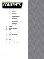
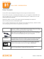
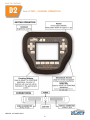
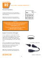
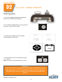
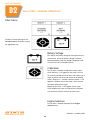
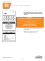
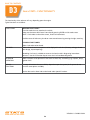

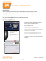
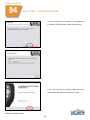
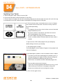
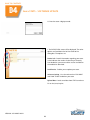
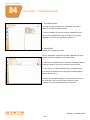
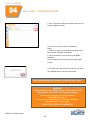
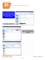
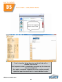
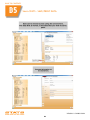
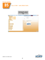
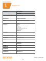
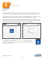
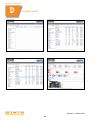
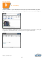
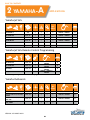
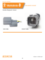
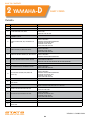

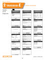
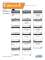
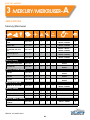
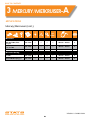
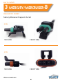
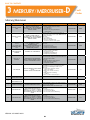
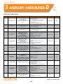

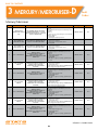
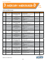
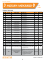
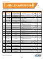
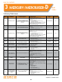
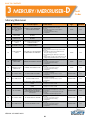
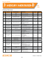

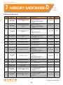
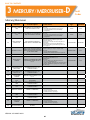
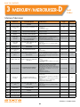
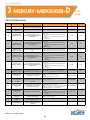
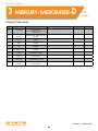
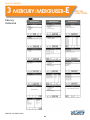
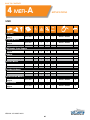
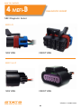
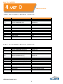
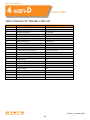
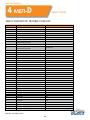
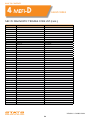


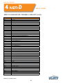
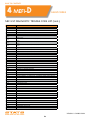
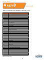
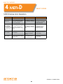
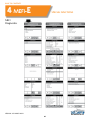
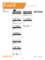
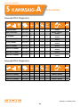
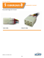
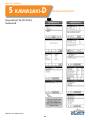
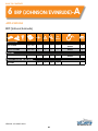
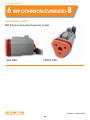
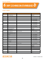
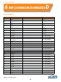
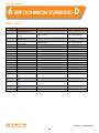
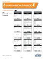
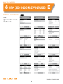
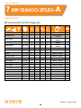
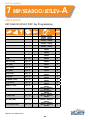
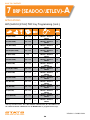
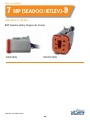
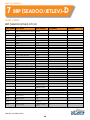
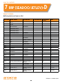
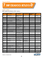
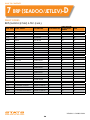
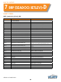

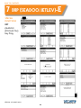

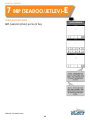
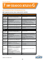
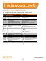
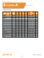
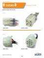
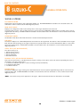
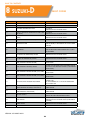
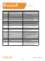
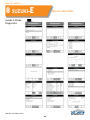
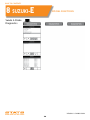
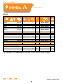
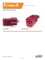
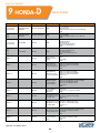
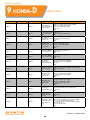
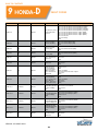
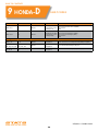
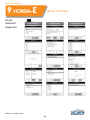
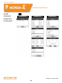
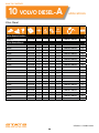
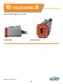
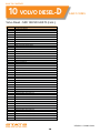
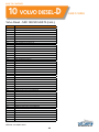
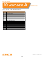
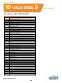

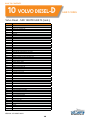
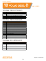
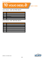

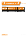
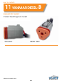


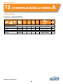
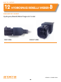
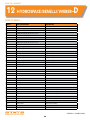
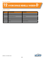
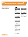

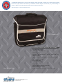


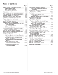


![[1 ] Oracle® Enterprise Manager](http://vs1.manualzilla.com/store/data/005669073_1-0396df232df5e560fdd03210f5126330-150x150.png)