1
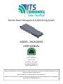
Remote Power Management & Monitoring System MODEL: 1RU8126MS USER MANUAL 2000 E Lake Mary Blvd
Sanford, FL 32773
(407) 894-8851 (800) 866-5699
[email protected]
WWW.ITSCOMMANDER.COM
Read this manual before using this product. Failure to follow the instruc ons and safety precau ons in this manual can result in serious injury. Keep this manual in a safe loca on for future reference. For other ITS Commander™ products, previous firmware versions and updates please go to our webpage at h p://www.ITSCOMMANDER.com Trademark and Copyright InformaƟon
This document is Copyright©2014 by Earnest Products Inc. dba Southern Manufacturing. All rights reserved. ITS Commander ™, ITS Commander … Take Control™, and Intelligent Transporta on Systems Commander are trademarks of Earnest Products Inc. 2014. All other company names, logos, or trademarks referenced herein are the property of their respec ve owners, and are for instruc ve, demonstra ve or example purposes only. No endorsement of the above referenced companies or products by Earnest Products Inc. dba Southern Manufacturing should be assumed or implied No part of this document shall be reproduced without explicit wri en permission from Earnest Products Inc. dba Southern Manufacturing. Earnest Products Inc. dba Southern Manufacturing, herea er referred to as EP, shall not be held liable for any damage or injury involving its enclosures and/or its remote power manager and monitoring system if used or operated in any manner or subject to any condi on inconsistent with its intended purpose, or if installed or operated in an unapproved manner, or improperly maintained. Although reasonable efforts have been made to ensure the informa on contained herein is as useful and as accurate as possible, EP assumes no responsibility for its applica on, usefulness, or completeness. EP will not be held responsible or liable under any circumstances for any damages or losses. Damages or losses include direct, indirect, special, incidental, or consequen al damages or losses arising from the use of any informa on contained herein or the use of any products or services referenced. EP reserves the right to change ITS Commander™ specifica ons, features, warran es, documenta on, pricing, terms and condi ons at any me, without no ce. V4.12 USER MANUAL ITS COMMANDER™ Model: 1RU8126MS … Take Control
Table of Contents
1. Introduc on .................................................................................. Package ........................................................................... Safety ............................................................................... Cer fica ons .................................................................... 2. General Informa on Specifica ons ................................................................... Features ........................................................................... 3. Installa on Moun ng ......................................................................... Installa on ....................................................................... Set Up .............................................................................. 4.User Interface Tabs Summary ......................................................................... Names and No fica ons ................................................. Scheduler ......................................................................... Unit Log ........................................................................... Configura on ................................................................... Configura on File ............................................................ Security ............................................................................ Firmware ......................................................................... 5. Technical Assistance ...................................................................... 6. Warranty ........................................................................................ V4.12 USER MANUAL 4 4 5 6 7 8 9 10 11 18 19 19 25 26 26 27 27 28 29 ITS COMMANDER™ Model: 1RU8126MS … Take Control
Introduc on The ITS Commander™ is designed to improve system reliability and lower the cost of ownership through reduced maintenance costs. The system benefits both the owning agency and maintaining agency by promptly sending signals of an abnormal situa on, allowing rou ne monitoring of cri cal equipment, and providing the capability to remotely control outlets to reboot equipment. These features can reduce unnecessary trips to inspect or service the cabinet thereby saving money. Southern Manufacturing’s ITS Commander™ may be integrated with ITS enclosures from the factory. Power panel and factory installed equipment are pre‐wired and connected. Package The contents of your package are: (1) ITS Commander™ Unit (2) Adjustable rack moun ng brackets (1) Power cord (1) Temperature Probe (1) Users Manual MIB, frequently asked ques ons and support provided at www.ITSCOMMANDER.com Page 4 V4.12 USER MANUAL ITS COMMANDER™ Model: 1RU8126MS SAFETY
Read this manual before using this product. Failure to follow the instruc ons and safety precau ons in this manual can result in serious injury . Keep this manual in a safe loca on for future reference. Safety Symbols
The following symbols have been placed thought this manual to reduce the risk of serious injury or death and to ensure the con nued safe opera on of this product. NOTE Notes provide addi onal informa on when comple ng a specific task or procedure. Notes will be designat‐
ed by a check mark inside a circle, the word NOTE and a line beneath which the informa on appears. CAUTION Cau on is used to provide safety informa on to prevent damage to the product or connected equipment. Cau on is designated by a yellow triangle with a black exclama on mark in the center, the word CAUTION and a line beneath which the informa on appears Page 5 V4.12 USER MANUAL ITS COMMANDER™ Model: 1RU8126MS CerƟficaƟons and Compliances
The ITS Commander™ is designed, tested and manufactured to meet the requirements of the following na onal safety standards: FCC Part 15 Class B This equipment has been tested and found to comply with the limits of Part 15 of the FCC Rules. These limits are designed to provide reasonable protec on against harmful interference in a residen al installa on. This equipment generates, uses and can radiate radio frequency energy and, if not installed and used in accordance with the instruc ons, may cause harmful interfer‐
ence to radio communica ons. However, there is no guarantee that interference will not occur in a par cular installa on. If this equipment does cause harmful interference to radio or televi‐
sion recep on, which can be determined by turning the equipment off and on, the user is en‐
couraged to try to correct the interference by one or more o f the following measures (1) Reori‐
ent or relocate the receiving antenna (2) Increase the separa on between the equipment and receiver (3) Connect the equipment into an outlet on a circuit different from that to which the receiver is connected (4) Consult the dealer or an experienced radio/TV technician for help. NEMA NEMA TS 2‐2003 v02.06 Sec ons 2.2.7.3—2.2.7.6 , 2.2.8.4 and 2.2.9 This equipment has been tested and found to comply with the NEMA TS 2‐2003 environmental requirements as are applicable for this device. The requirements applicable are (1) Opera ng voltage (2) Opera ng Frequency (3) Temperature and Humidity (4) Ambient Temperature (5) Humidity (6) Vibra on and (7) Shock. Page 6 V4.12 USER MANUAL ITS COMMANDER™ Model: 1RU8126MS SpecificaƟons
MODEL
INPUT OUTPUT ENVIRONMENTAL OTHER NOTES V4.12 1RU8126MS
Voltage Range 89 VAC‐ 135 VAC, 120 VAC (Nominal) 1 Rated Current 12 Amps Circuit Breaker 15 Amps Frequency Range 60 hertz ± 3 Hz AC Inlet IEC C16, 15A, 250 VAC, 60 Hz Power Cord NEMA 5‐15P to IEC‐C15, 15 A / 125 V Surge Suppression 10 kA, L‐N Outlet Quan ty 8 Outlet Type NEMA 5‐15R, 15A / 125 VAC, 60 Hz Dry Contact Input Quan ty 12 Dry Contact Input Connector 24 Posi on, Screw‐less Push‐In terminal, 16‐24 AWG Relay Quan ty 6 Relay Switching Voltage 250 VAC, 125 VDC Max Relay Contact Form SPST‐NO (1 Form A) Relay Contact Ra ng (Current) 10 A Relay Connector 12 Posi on, Screw Terminal, 12‐22 AWG Temperature Sensor Thermistor, R @ 25°C = 10k Ω, ± 1 % ( 4.1 feet /1.25m) Humidity Sensor 26mV / % RH ±3% RH, Linear, 3.3 V Supply Temperature / Humidity Connector 5 Posi on, Screw terminal, 16‐30 AWG Analog Inputs 2 Analog Input Connector 4 Posi on, Screw terminal, 16‐30 AWG Opera ng Temperature ‐34°C (‐30°F) to +74°C (+165°F) 1 Opera ng Humidity 0—95 % Rela ve Humidity1 Storage Temperature, Humidity ‐45°C (‐50°F) to +85°C (+185°F) / 0‐100% 1 Dimensions 1.7” x 5.5” x 19” Rack Space 1 RU (Rack Unit) Network 10/100/1000 Base‐T Ethernet Port, Auto MDI‐X Alert Types Email / SMS / User Interface / SNMP Clock NTP Scheduling 100 events, ON—OFF—RESET 1. Per NEMA TS2‐2003v02.06 ITS COMMANDER™ Model: 1RU8126MS Features
4 3 1 7 8 8 6 5 2 FRONT
11 14 9 10 12 13 REAR
ITEM
DESCRIPTION
ITEM DESCRIPTION
1 Input circuit breaker, 15A 8 Adjustable rack moun ng ears 2 Outlets, 15 A, Labeled A trough H 9 I/O Expansion Port 3 Unit Status indicator, Green 10 Analog Inputs 4 Outlet Status indicator, Green, labeled A through H 11 Temperature and Humidity Inputs 5 LCD Screen 12 Dry Contact inputs 1‐12 6 Select Bu on 13 Relay contacts 1‐6 7 Ethernet Port 14 AC Power In, IEC C16 Inlet Page 8 V4.12 USER MANUAL ITS COMMANDER™ Model: 1RU8126MS MounƟng
Choose the desired moun ng bracket loca on. Procedure
The ITS Commander is provided with moun ng brackets for a standard 19‐inch rack. Each moun ng ear is removable and adjustable towards the rear or the front . 1. Remove retaining screws from unit body 2. Choose the loca on of the bracket, by aligning the moun ng bracket holes to the unit body. 3. Secure using retaining screws 4. Repeat for the other side. Bracket LocaƟon OpƟons Front Front Front Flush Recessed Deep Recessed Rear Rear Rear Flush Recessed Deep Recessed NOTE Ensure to replace all screws in the moun ng holes. Empty screw holes should be filled. 5. Mount in a standard EIA 19” Rack with (4) #10 screws. Page 9 V4.12 USER MANUAL ITS COMMANDER™ Model: 1RU8126MS InstallaƟon
Stand Alone Configura on 1. Connect an Category 5 (CAT 5) patch cable to the ITS Commander Ethernet port. A straight‐through or crossover cable may be used. 2. Connect the other end of the RJ45 patch cable to the user interface (Laptop, PC, etc.). CAUTION Stand alone configura on does not provide network me synchroniza on (NTP). Logging, Scheduling and No fica on features will not be available Network Configura on Network Configura on 2 Network Configura on 1 1. Connect an RJ45 patch cable to the ITS Commander Ethernet Port. 2. Connect the other end of the RJ45 Patch cable to the network switch. 3. User interface may be accessed using a wireless router or direct connec on to the network. Page 10 V4.12 USER MANUAL ITS COMMANDER™ Model: 1RU8126MS Set Up
CAUTION Ensure input circuit breaker is in the OFF posi on before applying power to the unit. CAUTION Do not remove the MALE end of the power cord in order to “hardwire” the unit. Ensure proper safety standards are followed by using only listed or recognized power cords. Power
1. Ensure the input circuit breaker is in the OFF posi on before proceeding. 2. Connect the IEC‐C13 (FEMALE) end of the power cord to the rear of the unit. 3. Connect the NEMA 5‐15P (MALE) end of the power cord to the desired power source (receptacle). The desired power source may be a PDA (Power distribu on assembly) receptacle, or other appropriate power source. 1. The 15 A circuit breaker, located on the front of the unit, may also serve as an ON / OFF switch. NOTE If power or connec vity is lost to the unit, the below message will appear on the summary page. NOTE This unit has a safe shutdown feature. This feature provides a few seconds of back up power within the unit to safely shut down and send one last “packet” of informa on to the server. Page 11 V4.12 USER MANUAL ITS COMMANDER™ Model: 1RU8126MS Set Up
Outlets
1. Connect desired equipment to the outlet posi on using a NEMA 5‐15P Plug. 2. Outlet labels may be changed in the [Names and No fica ons] tab. 3. LEDs on the front of the unit labeled A—H indicate the ON / OFF status of each outlet. An illuminated LED means ON. OUTLETS Relays
1. Connect desired equipment to the relay posi on using 12—22 AWG wire. 2. Relay labels may be changed in the [Names and No fica ons] tab. 3. LEDs on the rear of the unit labeled Relay 1‐6 indicate the OPEN / CLOSED status of each relay . An illuminated LED means CLOSED (current is allowed to flow) NOTE Relay contact ra ng is 10 A max. Relay switching voltage is 250 VAC / 125 VDC max. Page 12 V4.12 USER MANUAL ITS COMMANDER™ Model: 1RU8126MS Set Up
CAUTION Inputs (Dry Contacts) provide their own voltage. DO NOT connect live power to Input (Dry Contact) terminals. Connec ng live power to Input (Dry Contact) terminals will result in severe damage to the unit. Input (Dry Contacts)
1. Ensure the input circuit breaker is in the OFF posi on before proceeding. 2. Connect the desired switch/equipment terminal to the Input posi on using 16—24 AWG wire. Do not connect live power to the input (dry contact) terminal. Connec ng live power will result in severe damage to the unit 3. Input labels may be changed in the [Names and No fica ons] tab. 4. Alarm status for normally open (NO) and normally closed (NC) contact closures may be changed in the [Names and No fica ons] tab. 5. LEDs on the rear of the unit labeled Input 1‐12 indicate the OPEN / CLOSED status of each input . An illuminated LED means a CLOSED input. NOTE The LEDs indica ng input status are not linked to the ALARM status in the [Names and No fica ons] tab. An illuminated LED means the contact is closed. A closed contact may be the normal condi on for that contact. Illumina on of an Input LED does not indicate an ALARM condi on. Page 13 V4.12 USER MANUAL ITS COMMANDER™ Model: 1RU8126MS Set Up
Humidity Probe (sold separately)
1. Ensure the input circuit breaker is in the OFF posi on before proceeding. 2. Connect the humidity probe to the following pins: Pin 1—3.3 V Pin 2—HUM Pin 3—GND 3. Humidity threshold levels may be changed in the [Names and No fica ons] tab. NOTE Please visit www.ITSCOMANDER.com to order a compa ble humidity probe for this unit. Temperature Probe
1. Connect the temperature probe to the following pins: Pin 4—TEMP Pin 5—GND 2. Temperature threshold levels may be changed in the [Names and No fica ons] tab. Analog Input
1. Connect desired equipment to the analog posi on using 16—30 AWG wire. 2. Analog threshold levels may be changed in the [Names and No fica ons] tab. NOTE Analog inputs have an isolated ground. Please do not connect chassis ground to this connector. I / O Expansion Port
The I/O Expansion Port is not implemented in this model. Page 14 V4.12 USER MANUAL ITS COMMANDER™ Model: 1RU8126MS Set Up
The ITS Commander™ can be configured using a web browser. To set up the unit: 1. Enter the following URL in the address bar. 2. When first accessing the user interface, log in to the unit using the default log in informa on. h p://192.168.0.50 User name: admin
Password: its
3. To configure the unit, select the [Configura on] System
Enter the desired system values System name (30 Characters) System loca on (30 Characters) System contact (30 Characters) Temperature Units ( °F / °C) Time zone Reset Interval (in seconds) [ 1– 254 seconds] Page 15 V4.12 USER MANUAL ITS COMMANDER™ Model: 1RU8126MS Set Up
CAUTION Incorrect se ngs may cause the unit to lose network connec vity. If connec vity is lost, hold down the front panel bu on to restore the unit to its default se ngs. Network
Enter the desired network and system parameters for the unit. [Save Configura on] at the bo om of the page to save changes. NOTE Once the default IP address is changed, navigate to the new IP address by entering the following URL in the address bar of the web browser. h p://{new IP address} Email / SMS
1. Enter the desired Email address in the recipient fields ( 1– 5) 2. For SMS text messaging use the cellphone carrier SMS gateway for email to SMS. 3. Enter the SMTP Server 4. If required by the SMTP server, enter the Username and Password 5. Select SSL if applicable. 6. Enter the Port NOTE Your SMTP server may not require a user name or password. NOTE Contact your cell provider for the correct SMS gateway address. Page 16 V4.12 USER MANUAL ITS COMMANDER™ Model: 1RU8126MS Set Up
SNMP
1. Enter up to 3 Read and Write Communi es as desired. 2. Select {No fica ons Enabled} if no fica ons (traps) are desired. 3. Enter the Receiver IP address 4. Enter the community name. NOTE Please visit www.ITSCOMMANDER.com to download the MIB for the SNMP traps. 5. Click Save Configura on to save changes Page 17 V4.12 USER MANUAL ITS COMMANDER™ Model: 1RU8126MS User Interface Tabs
Summary Tab
The [Summary] tab contains a live status of the following items: Dry Contact Inputs Power Outlets Relays Current Voltage Temperature Humidity Analog Inputs System Parameters Unit InformaƟon
Can be changed in the [Configura on] tab. Dry Contact Inputs
Labels can be changed in the [Names and No fica ons] tab Alarm status can be changed in the [Names and No fica ons] tab Dry contact inputs are green when in a non‐Alarm status. Default Alarm status is a closed contact. Dry contact inputs will turn red when in an Alarm status as set in the [Names and No fica ons] tab. Any state change will be reflected in the [Unit Log] tab. Power Outlets
Labels can be changed in the [Names and No fica ons] tab Outlets are green when on, they are grey when off Clicking the [ON] / [OFF] slider, will turn the outlet ON or OFF The reset bu on turns the outlet off then back on for a specified reset interval me. Default reset interval is 10 seconds, and can be changed in the [Configura on] tab, in the system sec on The reset bu on will Flash while rese ng Page 18 V4.12 USER MANUAL ITS COMMANDER™ Model: 1RU8126MS User Interface Tabs
Summary Tab (conƟnued)
Relays
Labels can be changed in the [Names and No fica ons] tab Relays are grey when open, they are green when closed Clicking the [OPEN] / [CLOSE] slider, will open or close the relay. OperaƟng Parameters
Current and Voltage are displayed for the unit Temperature and Humidity are displayed when sensors are connected, units of measurement can be changed in the [Configura on] tab. Will turn red when upper threshold is exceeded, and blue when lower thresholds are exceeded . Thresholds may be changed in the [Names and No fica ons] tab. Analog 1 and Analog 2 voltages are displayed when connected Network me and date are displayed when configured in a network System Parameters
Displays all system parameters. Can be changed in the [Configura on] tab Names and NoƟficaƟons Tab
The [Names and No fica ons] tab allows the user to provide meaningful names for: Outlets Relays Inputs Analog Inputs Power This tab also allows the user to set the types of no fica on requested (for all), alarm state (inputs only), and Lower / Upper Limits ( Analog and Environmental inputs). Email SNMP Page 19 V4.12 USER MANUAL ITS COMMANDER™ Model: 1RU8126MS User Interface Tabs
Names and NoƟficaƟons Tab (conƟnued)
Outlets
Outlet Labels can be changed for each outlet (max 30 characters) Select Email to receive an email no fica on ( all state changes) Select SNMP to receive a “trap” no fica on ( all state changes) Relays
Relay Labels can be changed for each outlet (max 30 characters) Select Email to receive an email no fica on ( all state changes) Select SNMP to receive a “trap” no fica on ( all state changes) Inputs
Input Labels can be changed for each outlet (max 30 characters) Select the Alarm State of Closed or Open ‐ Closed (Alarm status is when the contact is closed) ‐ Open ( Alarm status is when the contact is open) Re‐No fica on Interval can be set if re‐no fica on is desired a er the original alarm no fica on was sent. Select Email to receive an email no fica on ( Alarm Status) Select SNMP to receive a “trap” no fica on ( all state changes) Page 20 V4.12 USER MANUAL ITS COMMANDER™ Model: 1RU8126MS User Interface Tabs
Names and NoƟficaƟons Tab (conƟnued)
Analog Inputs
Analog Input Labels can be changed for each outlet (max 30 characters) Set Lower and Upper threshold limits Select Email to receive an email no fica on ( threshold limits) Select SNMP to receive a “trap” no fica on ( threshold limits) Enter the desired voltage hysteresis (default 1 volt) Environmental
Set Lower and Upper threshold limits Temperature units may be changed in the [configura on] tab. Select Email to receive an email no fica on ( threshold limits) Select SNMP to receive a “trap” no fica on ( threshold limits) Power
Select Email to receive an email no fica on on Power up or down Select SNMP to receive a “trap” no fica on Click Submit to save changes Page 21 V4.12 USER MANUAL ITS COMMANDER™ Model: 1RU8126MS User Interface Tabs
Scheduler Tab
The [Scheduler] tab allows the user to schedule up to 100 events. For each event, there are several op ons: Once
NAME: Event label can be changed (max 30 characters) TIME: Time for the desired event ON: Date for the desired event PORT : Outlet / Relay to be affected ACTION: Ac on taken during the event NEXT: Lets the user know (a er changes have been saved) when the next scheduled ac on is to take place for that event Daily Recurring
NAME: Event label can be changed (max 30 characters) TIME: Time for the desired event STARTING: Date for the first occurrence of the desired event PORT : Outlet / Relay to be affected ACTION: Ac on taken during the event RECUR: Every [ # ] days, forever or for a specified # of mes required NEXT: Lets the user know (a er changes have been saved) when the next scheduled ac on is to take place for that event Page 22 V4.12 USER MANUAL ITS COMMANDER™ Model: 1RU8126MS User Interface Tabs
Scheduler Tab (conƟnued)
Weekly Recurring
NAME: Event label can be changed (max 30 characters) TIME: Time for the desired event STARTING: Date for the first occurrence of the desired event OUTLET / RELAY : Outlet / Relay to affected ACTION: Ac on taken during the event RECUR: Every [ # ] weeks, forever or for a specified # of mes required NEXT: Lets the user know (a er changes have been saved) when the next scheduled ac on is to take place for that event Weekly PaƩern
NAME: Event label can be changed (max 30 characters) TIME: Time for the desired event ON: Days of the week when the event is to occur OUTLET / RELAY : Outlet / Relay to affected ACTION: Ac on taken during the event NEXT: Lets the user know (a er changes have been saved) when the next scheduled ac on is to take place for that event Page 23 V4.12 USER MANUAL ITS COMMANDER™ Model: 1RU8126MS User Interface Tabs
Scheduler Tab (conƟnued)
Monthly PaƩern
NAME: Event label can be changed (max 30 characters) TIME: Time for the desired event ON: Days of the month when the event is to occur (mul ple may be separated by a coma) OUTLET / RELAY : Outlet / Relay to affected ACTION: Ac on taken during the event MONTHS: Select months in which the event is to occur NEXT: Lets the user know (a er changes have been saved) when the next scheduled ac on is to take place for that event NOTE Ensure to click SAVE a er making the desired changes. NOTE The first screen always shows the first 10 events, to see more events click NEXT at the bo om of the page. NOTE Up to 100 events may be scheduled Page 24 V4.12 USER MANUAL ITS COMMANDER™ Model: 1RU8126MS User Interface Tabs
Unit Log
The [Unit Log] tab allows the user to view, download and set the interval for system status log. Select a records start date and click {Retrieve Log}, the first 10 log entries are displayed. Click {NEXT} to navigate trough further entries. To download the log file. Select the records start and stop date and click {Retrieve Log} NOTE The unit is able to save thousands of records. When the unit reaches the end of the allocated log memory, the oldest record will be over wri en. Download the log periodically in order to avoid losing data. Page 25 V4.12 USER MANUAL ITS COMMANDER™ Model: 1RU8126MS User Interface Tabs
ConfiguraƟon
The [Configura on ] tab allows the user to configure the unit as desired. This tab is covered in the SET UP sec on of this manual ConfiguraƟon File
The [Configura on File] tab allows the user to download and upload saved configura ons. In order to ease the set up of mul ple units, the configura on may be downloaded and saved in a user defined loca on. The configura on file may also be uploaded into a unit. Items covered in the configura on file: Schedule Names and No fica ons To download a configura on file 1. Click {Download Configura on} 2. File will automa cally download 3. Move file to desired loca on NOTE Different internet browsers require permissions to download this type of file. Contact your systems administrator for assistance in downloading the configura on file. To upload a configura on file 1. Click {Choose File} 2. Navigate to the configura on file desired 3. Click {Upload Configura on} 4. Configura on is not loaded into the unit Page 26 V4.12 USER MANUAL ITS COMMANDER™ Model: 1RU8126MS User Interface Tabs
Security
The [Security ] tab allows the user to change the password assigned to the unit To change the password: 1. Enter the old password (Default: its) 2. Enter the new password 3. Click {Change Password} to enact changes. Firmware
The [Firmware] tab allows the user to change the download firmware updates. Please visit www.ITSCOMMANDER.com to download firmware updates for this unit. To download a firmware update: 1. Click {Choose File} 2. Navigate to the downloaded firmware file 3. Click {Upload} 4. Once the file has uploaded, verify that the new firmware version appears as a Staged firmware version, to un‐do the staging simply click {unstage} 5. Click {Reset} to apply the new firmware NOTE Please visit www.ITSCOMMANDER.com for firmware updates Page 27 V4.12 USER MANUAL ITS COMMANDER™ Model: 1RU8126MS Technical Assistance
NOTE Please visit www.ITSCOMMANDER.com for Q & A and Technical Assistance. You may also email us at [email protected] or phone us at (800) 866‐5699 Page 28 V4.12 USER MANUAL ITS COMMANDER™ Model: 1RU8126MS