1
Ethernet controller TCW121B
User manual
1. Short description
TCW121B is a multifunctional device for remote monitoring and management. It is an Ethernet
based controller, which is designed to work in IP-based networks and managed by WEB interface or
SNMP programs. Its I/O interface - relay outputs, analog and digital inputs, is suitable for solving specific
problems in various fields such as remote control, alarm systems, industrial process automation, control
and management of computer networks etc.
2. Features
10 Mb Ethernet connectivity;
Password protected web based configuration and control;
2 digital inputs with "logic level" and "dry contact" modes;
2 analog inputs with switchable range - 0 ÷ 5 VDC or 0 ÷ 100 VDC;
2 relays with NO and NC contacts;
Long 1-Wire support, for up to 2 temperature sensorsTST1XX or up to 2
temperature/humidity sensors TSH2xx;
Temperature & humidity monitoring and control;
SNMP v.1 and VLAN support;
SMTP with authorization (SSL is not supported);
Sending SNMP Traps messages under certain conditions;
Sending E-mail messages under certain conditions;
MAC Address filtering;
Remote FTP firmware update.
3. Technical parameters
Supply voltage, VDC
Maximum current ( with both relays ON), mA
Weight, g
Dimensions, mm
Operating temperature, °C
Minimum high level input voltage for digital inputs, VDC
Maximum low level input voltage for digital inputs, VDC
Maximum input voltage for digital inputs, VDC
Analog input 1 range (hardware configurable), VDC
Analog input 2 range (hardware configurable), VDC
Maximum switchable current (at 220 VAC) , А
Maximum switchable voltage, VAC/VDC
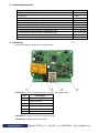
4. Connectors
Inputs and outputs locations are shown below:
Connector 1 – 6-pin connector pinout is shown in the table below:
Pin
description
1
Relay1 normally open
2
Relay1 common
3
Relay1 normally closed
4
Relay2 normally open
5
Relay2 common
6
Relay2 normally closed
Connector 2 – power connector (center positive).
Connector 3 – RJ45 Ethernet connector
12±2
170
106
107 x 72 x 32
0 ÷ 40
2.5
0.8
5.5
0 ÷ 5 / 0 ÷ 100
0 ÷ 5 / 0 ÷ 100
1
250/110
Connector 4 – 8-pin connector pinout is shown in the table below:
Pin
description
Digital input 1 (Din1). Operating mode is selected by
1
jumper DI1- dry contact (close) and logic level (open).
Digital input 2 (Din2). Operating mode is selected by
2
jumper DI2 - dry contact (close) and logic level (open).
3
GND
Analog input 1 (Ain1). Range is selected by jumper AI1 –
4
0 ÷ 5VDC (close) and 0 ÷ 100VDC (open).
Analog input 2 (Ain2). Range is selected by jumper AI2 –
5
0 ÷ 5VDC (close) and 0 ÷ 100VDC (open).
6
GND
7
1-Wire data
8
1-Wire power supply (5VDC)
5. LED indicators
The following indicators show the status of the controller:
Relay1/Relay2 (green) – these LEDs are illuminated whenever the corresponding relay is
activated (the NO contact is closed and the NC contact is open);
Sts (red) – this flashes when the power supply is turned on;
Log (yellow) – this LED indicates that someone is connected to the controller through the
web interface;
Link (green) – this LED is located on the Ethernet connector. It indicates that the device is
connected to the network;
Act (yellow) – this LED is located on the Ethernet connector. It flashes when activity is
detected on the network.
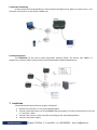
6. Example Applications
6.1 Remote control
The controlled device is connected in series with the relay contacts. Users can operate TCW121B
using a web browser or SNMP application. Both relays are managed independently.
6.2 Remote monitoring
A relay contact of monitored device is connected to the digital input. When an event occurs – the
controller can sends an e-mail and/or SNMP trap.
6.3 Data acquisition
The TCW121B can be used in Data Acquisition Systems (DAQ). The device uses SNMP v.1
protocol for communication with monitoring and management software applications.
7. Installation
Please follow the steps below for proper installation :
1. Mount the controller in a dry and ventilated place.
2. Connect the Ethernet port to a 10/100MB Ethernet network. For direct connection to a PC use
a “crossover” cable.
3. Connect the I/O pins of the controller according to the required application.
4. Connect the power supply.
If the red LED blinks, the power supply is OK. By default TCW121B comes with the following
network settings:
IP address: 192.168.1.2, Subnet Mask: 255.255.255.0, Default Gateway: 192.168.1.1
Communication with TCW121B can be established by assigning a temporary IP address to the
computer. This address should be in the same network (for example 192.168.1.3). To get access to the web
interface, you should type http://192.168.1.2 into the browser.
If the network settings are correct, the “Login” page will appear.
8. Web-based setup.
The web based interface allows configuration, monitoring and control. Recommended browser is
Internet Explorer at 1024x768 resolutions.
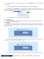
8.1 Login page
After opening the Login page, authorization data must be entered (by default username=admin ,
password=admin). It is recommended to change the username and password to prevent unauthorized
access to the controller.
The controller supports one active session – only one user can operate the device. If another user
tries to login, the message “Someone’s logged in” appears:
The active session will be terminated automatically, if the current user stays inactive for 2 minutes.
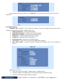
8.2 Monitoring page
After successful authorization, the “Monitoring” page appears:
The “Monitoring” page provides information about the state of the relays and digital inputs, values
of analog voltages (applied on analog inputs), temperature and humidity.
The state of the relay can be changed by appropriate “ON/OFF” button. To change the state of relay
for a while “Pulse” button should be pressed. Duration of the pulse is specified in “Pulse Duration” field of
“I/O Setup” page.
8.3 I/O setup page
I/O settings can be made here.
For temperature, humidity and analog value MIN, MAX and HISTERESYS values can be set. These
values arranged windows for monitored parameter.
Every going out of range generates e-mail (if enabled). The subject of message is “Host name”
defined in “Network setup” page. The body of message is description of parameter, generated e-mail.
It is necessary to set SMTP server settings on "Network Setup" page, to successfully send e-mails.
Leaving range is considered when the parameter goes lower than MIN values or higher than MAX.
Coming back in the range is consider when the parameter goes lower than (MAX – HISTERESYS) or higher
than (MIN + HISTERESYS).
For analog input similar range can be set. It is mandatory that chosen range correspond with the
range selection jumper J1 - 0÷5VDC (close) or 0÷100VDC (open).
For digital inputs, conditional e-mail sending can be arranged by following part of the page:
Relays can be activated automatically depends of value of monitored parameter (humidity,
temperature, analog voltage and changes on digital inputs) or manually. Only one parameter can be
assigned for relay activation, at the same time:
When manual activation is selected, “Pulse” and “ON/OFF” buttons on “Monitoring” page are
active. The duration of pulse for relay activation can be set from 1 to 253 seconds.
For all monitored parameters only one e-mail recipients can be set.
Automatic monitoring page refresh interval can be set from 1 to 253 second. If 0 is chosen - no
automatic refresh. Default value is 10 seconds.
8.5 Network Setup page
The Network parameters are set on this page.
For “IP configuration” and “MAC address” section, following parameters can be changed:
IP configuration – IP Address can be static or dynamic (DHCP server should be present in the
network);
IP address, Subnet mask , Default gateway – these fields are active if IP address is static;
DNS – these fields is mandatory, if domain names are used instead of IP addresses. By default
DNS has the same Ip address as Default gateway;
Time Server and Time Zone – these fields are not mandatory, they are used when e-mail must
be sent;
Host Name – up to 16 symbols, it appears as a “Subject” in sent e-mails;
MAC – device MAC address.
The good practice is to change the default IP address of controller immediately after first power-on.
This will avoid collisions if many devices are used in the same network. It may be necessary to clear the arp
cache, each time you connect a new device to the network. This is done by typing arp -d in the command
prompt window of computer.
VLAN and MAC address filtering are supported. Up to 3 MAC addresses (including Default Gateway)
can be active in MAC filtering.
Attention! If you are not familiar with VLAN and MAC filtering leave these sections by default.
To set up the SMTP server details, the following fields should be completed:
Mail server [IP:port] – domain or IP address and port of SMTP mail server;
E-mail – sender e-mail;
Username and Password – authentication details for mail server.
Mail server is considered server for sending mails. Secure Socket Layer is not supported.
Authentication details for WEB access to TCW121B can be set in the last section. Only one user is
supported.
8.6 SNMP Setup page
TCW121B supports SNMP v.1. This enables the device to be part of large monitoring and control
networks. The possible settings for “SNMP” section are:
SNMP Configuration – enable/disable SNMP;
Read-Write community – performs client authentication;
Read-Only community – performs client authentication;
SNMP Traps – enable/disable SNMP trap messages;
IP address – IP address of the receiving host
Community string – performs client authentication
Trap Interval - time interval in seconds for SNMP trap messages;
Max. Traps number – maximum number of SNMP trap messages sent, if trap condition is
present.
SNMP traps are sent if:
event occurs (status change) on Digital Input 1 or Digital Input 2;
measured voltage on Analog Input 1 or Analog Input 2 goes outside the range;
measured temperature goes outside the range;
measured humidity goes outside the range;
restart condition.
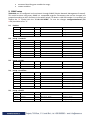
9. SNMP setup
TCW121B can be configured and monitored through SNMP (Simple Network Management Protocol).
This could be done using every SNMP v.1 compatible program. Parameters that can be changed, are
grouped according to their functions in the tables below. To obtain a valid OID number it is necessary to
replace the “x” symbol with the ”1.3.6.1.4.1.38783”. To save the changes configurationSaved (OID
x.8.0) should be set to "1".
9.1
9.2
9.3
9.4
9.5
Product
OID
Name
x.1.1.0
name
x.1.2.0
x.1.3.0
Access
Description
Syntax
read-only
Device name
String
version
read-only
Firmware version
String
date
read-only
Release date
String
Description
Syntax
Setup -> network
OID
Name
Access
x.2.1.1.0
deviceIPAddress
read-write Device IP address
IpAddress
x.2.1.2.0
subnetMask
read-write Subnet Mask
IpAddress
x.2.1.3.0
gateway
read-write Gateway
IpAddress
x.2.1.4.0
deviceMACAddress
read-write Device MAC Address
OCTET STRING (SIZE(6))
x.2.1.5.0
dhcpConfig
read-write DHCP configuration ON/OFF
INTEGER { ON(1), OFF(0) }
x.2.1.6.0
DNS
read-write Domain Name Server address
IpAddress
x.2.1.7.0
Hostname
read-write Device hostname
String (SIZE (0..38))
Syntax
Setup -> VLAN
OID
Name
Access
Description
x.2.2.1.0
VLANStatus
read-write VLAN status ENABLED/DISABLED
INTEGER { ENABLED(1), DISABLED(0) }
x.2.2.2.0
VlanId
read-write VLAN ID (0 – 4095)
INTEGER (0..4095)
Access
Description
Syntax
MAC Filter 1
OCTET STRING (SIZE(6))
Setup -> macFilter
OID
Name
x.2.3.1.0
filterMACAddress1
read-only
x.2.3.2.0
filterMACEnable1
read-write MAC Filter 1 ENABLED/DISABLED
INTEGER { ENABLED(1), DISABLED(0) }
x.2.3.3.0
filterMACAddress2
read-write MAC Filter 2
OCTET STRING (SIZE(6))
x.2.3.4.0
filterMACEnable2
read-write MAC Filter 2 ENABLED/DISABLED
INTEGER { ENABLED(1), DISABLED(0) }
x.2.3.5.0
filterMACAddress3
read-write MAC Filter 3
OCTET STRING (SIZE(6))
x.2.3.6.0
filterMACEnable3
read-write MAC Filter 3 ENABLED/DISABLED
INTEGER { ENABLED(1), DISABLED(0) }
Syntax
Setup -> SMTP
OID
Name
Access
Description
x.2.4.1.0
smtpServerAddress
read-write SMTP server address
IpAddress
x.2.4.2.0
smtpPort
read-write SMTP port (1 - 65535)
INTEGER (0..65535)
x.2.4.3.0
senderEmailAddress
read-write Sender e-mail address
String (SIZE (0..38))
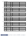
9.6
9.7
9.8
9.9
Setup -> SNMP
OID
Name
Access
Description
Syntax
x.2.5.1.0
SNMPConfiguration
read-write SNMP Configuration
INTEGER { ENABLED(1), DISABLED(0) }
x.2.5.2.0
trapEnabled
read-write TRAP messages ENABLED/DISABLED
INTEGER { Yes(1), No(0) }
x.2.5.3.0
trapReceiverIPAddress
read-write TRAP receiver IP address
IpAddress
x.2.5.4.0
trapCommunity
read-write TRAP community
String (SIZE (0..13))
x.2.5.5.0
trapInterval
read-write TRAP messages interval
INTEGER (0..255)
x.2.5.6.0
maxNumberOfTraps
read-write Maximum number SNMP traps
INTEGER (0..255)
Setup -> sensor1 -> temperature1
OID
Name
Access
Description
Syntax
x.2.6.1.1.0
temperature1Min
read-write Temperature1 range (min. value)
INTEGER (-1000..2000)
x.2.6.1.2.0
temperature1Max
read-write Temperature1 range (max. value)
INTEGER (-1000..2000)
x.2.6.1.3.0
temperature1Hyst
read-write Hysteresis
INTEGER (-1000..2000)
x.2.6.1.4.0
temperature1Action
read-write Temperature1 action
INTEGER {SEND_MAIL(1),NO_ACTION(0) }
Setup -> sensor1 -> humidity1
OID
Name
Access
Description
Syntax
x.2.6.2.1.0
humidity1Min
read-write Humidity1 range (min. value)
INTEGER (-1000..2000)
x.2.6.2.2.0
humidity1Max
read-write Humidity1 range (max. value)
INTEGER (-1000..2000)
x.2.6.2.3.0
humidity1Hyst
read-write Hysteresis
INTEGER (-1000..2000)
x.2.6.2.4.0
humidity1Action
read-write Temperature1 action
INTEGER {SEND_MAIL(1),NO_ACTION(0) }
Setup -> sensor2 -> temperature2
OID
Name
Access
Description
Syntax
x.2.7.1.1.0
temperature2Min
read-write Temperature2 range (min. value)
INTEGER (-1000..2000)
x.2.7.1.2.0
temperature2Max
read-write Temperature2 range (max. value)
INTEGER (-1000..2000)
x.2.7.1.3.0
temperature2Hyst
read-write Hysteresis
INTEGER (-1000..2000)
x.2.7.1.4.0
temperature2Action
read-write Temperature2 action
INTEGER {SEND_MAIL(1),NO_ACTION(0) }
9.10 Setup -> sensor2 -> humidity2
OID
Name
Access
Description
Syntax
x.2.7.2.1.0
humidity2Min
read-write Humidity2 range (min. value)
INTEGER (-1000..2000)
x.2.7.2.2.0
humidity2Max
read-write Humidity2 range (max. value)
INTEGER (-1000..2000)
x.2.7.2.3.0
humidity2Hyst
read-write Hysteresis
INTEGER (-1000..2000)
x.2.7.2.4.0
humidity2Action
read-write Temperature2 action
INTEGER {SEND_MAIL(1),NO_ACTION(0) }
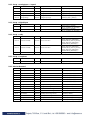
9.11 Setup -> analogInput -> input1
OID
Name
Access
Description
Syntax
x.2.8.1.1.0
voltage1Min
read-write Voltage1 alarm range (min. value)
String (SIZE (0..6))
x.2.8.1.2.0
voltage1Max
read-write Voltage1 alarm range (max. value)
String (SIZE (0..6))
x.2.8.1.3.0
voltage1Hyst
read-write Voltage1 hysteresis
String (SIZE (0..6))
x.2.8.1.4.0
voltage1Action
read-write Voltage1 action
INTEGER {SEND_MAIL(1),NO_ACTION(0) }
x.2.8.1.5.0
voltage1Range
read-write Voltage1 input range
INTEGER { 0_5V(0), 0_100V(1) }
9.12 Setup -> analogInput -> input2
OID
Name
Access
Description
Syntax
x.2.8.2.1.0
Voltage2Min
read-write Voltage2 alarm range (min. value)
String (SIZE (0..6))
x.2.8.2.2.0
Voltage2Max
read-write Voltage2 alarm range (max. value)
String (SIZE (0..6))
x.2.8.2.3.0
Voltage2Hyst
read-write Voltage2 hysteresis
String (SIZE (0..6))
x.2.8.2.4.0
Voltage2Action
read-write Voltage2 action
INTEGER {SEND_MAIL(1),NO_ACTION(0) }
x.2.8.2.5.0
Voltage2Range
read-write Voltage2 input range
INTEGER { 0_5V(0), 0_100V(1) }
Syntax
9.13 Setup -> digitalinput
OID
Name
Access
Description
x.2.9.1.0
digitalinput1Action
read-write Digital Input1 action
x.2.9.2.0
digitalinput2Action
read-write Digital Input2 action
INTEGER { MAIL_IF_RISING(2),
MAIL_IF_FALLING(1), NO_ACTION(0) }
INTEGER { MAIL_IF_RISING(2),
MAIL_IF_FALLING(1), NO_ACTION(0) }
9.14 Setup -> relay
OID
Name
Access
Description
Syntax
INTEGER { DIGITAL_INPUT2(8),
ANALOG_INPUT2(7), HUMIDITY2(6),
TEMPERATURE2(5), DIGITAL_INPUT1(4),
ANALOG_INPUT1(3), HUMIDITY1(2),
TEMPERATURE1(1), MANUAL(0) }
INTEGER { DIGITAL_INPUT2(8),
ANALOG_INPUT2(7), HUMIDITY2(6),
TEMPERATURE2(5), DIGITAL_INPUT1(4),
ANALOG_INPUT1(3), HUMIDITY1(2),
TEMPERATURE1(1), MANUAL(0) }
x.2.10.1.0
relay1ControlledBy
read-write Relay1 control item
x.2.10.2.0
relay2ControlledBy
read-write Relay2 control item
x.2.10.3.0
relayPulseWidth
read-write Digital Inputs mail recipient
INTEGER{ 0..255 }
Syntax
9.15 Setup -> recipients
OID
Name
Access
Description
x.2.11.1.0
recipient1EmailAddress
read-write Recipient1 e-mail
String (SIZE (0..38))
9.16 Monitor&control
OID
Name
Access
Description
Syntax
x.3.1.0
digitalInput1State
x.3.2.0
digitalInput2State
read-only
Digital Input1 state
INTEGER { ON(1), OFF(0) }
read-only
Digital Input2 state
INTEGER { ON(1), OFF(0) }
x.3.3.0
relay1State
read-write Relay1 state
INTEGER { ON(1), OFF(0) }
x.3.4.0
relay1Pulse
read-write Relay1 pulse
INTEGER { ON(1), OFF(0) }
x.3.5.0
relay2State
read-write Relay2 state
INTEGER { ON(1), OFF(0) }
x.3.6.0
relay2Pulse
read-write Relay2 pulse
INTEGER { ON(1), OFF(0) }
x.3.7.0
voltage1x10Int
read-only
Voltage1 x10 in integer format
INTEGER{ 0..65000 }
x.3.8.0
voltage2x10Int
read-only
Voltage2 x10 in integer format
INTEGER{ 0..65000 }
x.3.9.0
temp1x10Int
read-only
Temperature1 x10 in integer format
INTEGER{ -400..1750 }
x.3.10.0
temp2x10Int
read-only
Temperature2 x10 in integer format
INTEGER{ -400..1750 }
x.3.11.0
humi1x10Int
read-only
Humidity1 x10 in integer format
INTEGER{ 0..65000 }
x.3.12.0
humi2x10Int
read-only
Humidity2 x10 in integer format
INTEGER{ 0..65000 }
x.3.13.0
configurationSaved
read-write Configuration save status
INTEGER { SAVED(1), UNSAVED(0) }
x.3.14.0
restartDevice
read-write Restart device
INTEGER { RESTART(1), CANCEL(0) }
10.Restoring factory default settings
If the IP address or password is forgotten, TCW121B can be restored to its original factory default
settings. To do this, please follow the steps below:
Turn off the power supply;
Press and hold the RESET button then turn on the power supply;
The LED’s STS and LOG will flash 14 times, after that they will turn on. In this moment the
RESET button should be released.
The factory default settings are:
User Name (Admin)
admin
Password (Admin)
admin
IP Address
192.168.1.2
Subnet Mask
255.255.255.0
Default Gateway
192.168.1.1
SNMPConfiguration
disabled
readCommunity
public
writeCommunity
private
11. Firmware update
TCW121B supports remote firmware update. To update the device follow the steps below:
Download the TCW1XX_Update_Tool from www.teracom.cc;
Download the latest firmware version file (*.cod) from www.teracom.cc;
Start the program and upload the new firmware.
Attention! Don’t turn off the power supply during the update. Turning off the power supply
will damage the device.
Rev. 2 – October, 2011