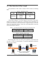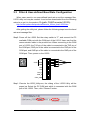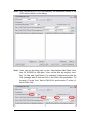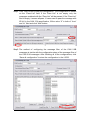
1
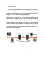
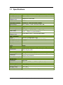
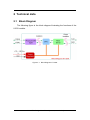
The I-2533 CAN to Fiber Bridge
User Manual
Warranty
All products manufactured by ICP DAS are under
warranty regarding defective materials for a period of one
year from the date of delivery to the original purchaser.
Warning
ICP DAS assumes no liability for damages resulting
from the use of this product. ICP DAS reserves the right to
change this manual at any time without notice. The
information furnished by ICP DAS is believed to be
accurate and reliable. However, no responsibility is
assumed by ICP DAS for its use, or for any infringements
of patents or other rights of third parties resulting from its
use.
Copyright
Copyright 1997 by ICP DAS. All rights are reserved.
Trademark
The names used for identification only may be
registered trademarks of their respective companies.
I-2533 CAN to Fiber Bridge User Manual (ver. 1.0, 2010/01/07) ------1
Tables of Content
Tables of Content...........................................................................................2
1 Introduction.............................................................................................3
1.1 Specifications ................................................................................4
1.2 Features..........................................................................................5
2 Technical data .........................................................................................6
2.1 Block Diagram................................................................................6
2.2 Appearance ....................................................................................7
2.3 Pin Assignment..............................................................................8
2.4 Rotary Switch .................................................................................9
2.5 LED Indicator ...............................................................................10
2.6 Terminator Resistor Setup .......................................................... 11
2.7 Wire Connection ..........................................................................13
3 Network Deployment ............................................................................14
3.1 Driving Capability ........................................................................14
3.2 Fiber Selection & Fiber Length...................................................15
3.3 Filter & User-defined Baud Rate Configuration ........................16
4 Dimension .............................................................................................22
I-2533 CAN to Fiber Bridge User Manual (ver. 1.0, 2010/01/07) ------2
1 Introduction
I-2533 is a local CAN bridge used to establish a connection between two
CAN bus system via fiber optic transmission medium. In order to solve the
problem between CAN and fiber transmission medium, I-2533 is specially
designed for converting the electrical CAN bus signal to fiber optic cables. Not
just like I-2533, I-2533 has three more important features.
First, the transmission distance limitation of the CAN bus system will not
reduced because of CAN baud rate. It means that the total network distance
can be extended. Second, the bus error on one CAN network will not affect the
operation of another CAN network. Finally, the two CAN network can
communication with each other by using different CAN baud rate for highly
flexibility. Besides, I-2533 provides the utility tool for user-defined baud rate
and filter configuration. By using this tool, it is allowed to have user-defined
baud rate and message filter. When users use the I-2533 on two CAN network
with different CAN baud rate, it may be useful to reduce the bus loading on the
network which has low baud rate.
I-2533 CAN to Fiber Bridge User Manual (ver. 1.0, 2010/01/07) ------3
1.1 Specifications
CAN Interface
Connector
Baud Rate (bps)
Transmission
Distance (m)
Isolation
Terminator Resistor
Specification
Fiber Interface
Connector
Wave Length
Fiber Cable
Transmission
Distance (m)
UART Interface
COM 1
COM 1 Connector
Baud Rate (bps)
Data bit
Stop bit
Parity
LED
Round LED
Power
Power supply
Protection
Power Consumption
Mechanism
Installation
Dimensions
Environment
Operating Temp.
Storage Temp.
Humidity
Screwed terminal block (CAN_GND, CAN_L, CAN_H)
10 k ~ 1 M
Depend on baud rate
2500 Vrms
Switch for 120Ω terminator resistor
ISO-11898-2, CAN 2.0A and CAN 2.0B
ST (Multi-mode)
850 nm
50 / 125 μm , 62.5 / 125 μm, 100 / 140 μm
(62.5 / 125μm is recommended)
2 km max (in 62.5 / 125 μm fiber cable)
RS-232 (configuration only)
Screwed terminal block (RxD, TxD, GND)
115200
8
1
None
PWR LED, CAN_Tx LED, CAN_Rx LED, CAN_Err
LED, FB_Err LED
Unregulated +10 ~ +30 VDC
Power reverse polarity protection,
brown-out protection
3W
Over-voltage
DIN-Rail
32.3mm x 77.5mm x 99.0mm (W x L x H)
-25 ~ 75 ℃
-40 ~ 80 ℃
5 ~ 95% RH, non-condensing
I-2533 CAN to Fiber Bridge User Manual (ver. 1.0, 2010/01/07) ------4
1.2 Features
z
z
z
z
z
z
z
z
z
z
z
z
z
Fiber Port: ST (Multi-mode)
Maximum transmission distance up to 2 km at any CAN baud rate
82C250 CAN transceiver
2500 Vrms isolation on the CAN side
Support both CAN 2.0A and CAN 2.0B
Fully compatible with the ISO 11898-2 standard
Rotary switch for CAN baud rate configuration
Build-in switch for 120 Ω terminator resistor
Up to 100 CAN nodes on each channel
Removable terminal block, Mount easily on DIN-Rail
Allow user-defined baud rate
Fiber broken line detection
Utility tool for message filter configuration
I-2533 CAN to Fiber Bridge User Manual (ver. 1.0, 2010/01/07) ------5
2 Technical data
2.1 Block Diagram
The following figure is the block diagram illustrating the functions of the
I-2533 module.
Figure 2-1 Block Diagram of I-2533
I-2533 CAN to Fiber Bridge User Manual (ver. 1.0, 2010/01/07) ------6
2.2 Appearance
Rotary Switch
0~9: Default baud rate
A: User-defined baud rate
B~E: N/A
F: Utility configuration
Front View
Bottom View
LED Indicators
Fiber Port
Connector Type: ST
Wavelength: 850nm
Fiber Type:
Multi-Mode, 50/125μm,
62.5/125μm, 100/140μm
COM Port
Only for utility tool
COM Port
ISO 11898-2 standard
Power Connector
+10 ~ +30VDC between
+VS and GND
DIP Switch
Enable or disable 120Ω terminator resistor
Figure 2-2 Appearance of I-2533
I-2533 CAN to Fiber Bridge User Manual (ver. 1.0, 2010/01/07) ------7
2.3 Pin Assignment
The pin assignments of COM port, CAN port, fiber port and power
connector of I-2533 are shown in the following tables.
Table 2-1 Pin Assignment
Port
COM
CAN
Fiber
Power
Name
Description
TXD
TXD pin of RS-232 port.
RXD
RXD pin of RS-232 port.
GND
SG (or GND) pin of RS-232 port.
CAN_L
CAN_Low, signal line of CAN port.
CAN_H
CAN_High, signal line of CAN port.
CAN_GND
CAN_Ground, ground voltage level of CAN port.
TXD
Transmit optic data.
RXD
Receive optic data.
+VS
Voltage Source Input. +10VDC ~ +30V VDC.
GND
Power Ground.
F.G.
Frame Ground.
Sometimes, the CAN_GND voltage level of different CAN devices on a
CAN bus system are not equal. In this case, it could cause some problems and
derogate the system stability. There is one way to relieve this situation; users
can connect the CAN_GND of different CAN devices with each other to
balance the voltage level of CAN_GND.
Electronic circuits are always influenced by different levels of
Electro-Static Discharge (ESD), which become worse in a continental climate
area. F.G. provides a path for conducting the ESD to the earth ground.
Therefore, connecting the F.G correctly can enhance the capability of the ESD
protection and improve the module’s reliability.
Wiring of CAN_GND and F.G. is not necessary; users can modify the
configuration of wiring according to real applications.
I-2533 CAN to Fiber Bridge User Manual (ver. 1.0, 2010/01/07) ------8
2.4 Rotary Switch
When users would like to set the CAN baud rate or message filter of
I-2533, use the rotary swich on the upper of the power connector to archieve
this purpose. Users can find it on the top of the power connector.
2
6
E
A
BC D
345
Rotary switch for
CAN baud rate
Figure 2-3 Location of Rotary Switch
There are 16 sections on the rotary switch. They are descripted on the
following table.
Table 2-2 Description of Rotary Switch
Switch Value
Description
0
Set baud rate to 10 kbps
1
Set baud rate to 20 kbps
2
Set baud rate to 50 kbps
3
Set baud rate to 80 kbps
4
Set baud rate to 100 kbps
5
Set baud rate to 125 kbps
6
Set baud rate to 250 kbps
7
Set baud rate to 500 kbps
8
Set baud rate to 800 kbps
9
Set baud rate to 1 Mbps
A
Set baud rate to user-defined baud rate which is configured
by I-2533 utility.
B~E
F
Not-available
Set I-2533 into configuration mode.
I-2533 CAN to Fiber Bridge User Manual (ver. 1.0, 2010/01/07) ------9
2.5 LED Indicator
There are 5 LEDs on the I-2533. One for power indication, three for CAN
bus indication and one for fiber indication. The LED assignment and
description are shown as follows.
Figure 2-4 LED Assignment of I-2533
LED Name
Color
PWR
Red
Description
When power on the I-2533, this LED is turned on.
CAN_Tx
Green When I-2533 sends one CAN message to CAN bus,
this LED flashes once. Therefore, if bus loading is
heavy, the LED will be always on.
CAN_Rx
Green When I-2533 receives one CAN message from CAN
bus, this LED flashes once. Therefore, if bus loading
is heavy, the LED will be always on.
CAN Err
Red
1. If I-2533 detects the bus-off status on the CAN
bus, this LED is always on.
2. If I-2533 can’t send CAN messages successfully
because the bus connector is off or some errors
happen, this LED flashes five times per second.
3. If the CAN data buffer is full, this LED flashes once
per second.
Fiber Err
Red
1. If the I-2533 detects the RXD line of the fiber is off,
this LED is always on.
2. If the fiber data buffer is full, this LED flashes once
per second.
Table 2-3 LED Description
I-2533 CAN to Fiber Bridge User Manual (ver. 1.0, 2010/01/07) ------10
2.6 Terminator Resistor Setup
In order to minimize the reflection effects on the CAN bus line, the CAN
bus line has to be terminated at both ends by two terminator resistors as in the
following figure. According to the ISO 11898-2 spec, each terminator resistor is
120Ω (or between 108Ω~132Ω). The bus topology and the positions of these
terminator resistors are shown as following figure.
Device 1
Device 2
Device N
120Ω
120Ω
CAN_H
CAN_L
Figure 2.5
CAN bus network topology
Each I-2533 includes one build-in 120Ω termintor resistor, users can
decide if it is enabled or not. The DIP switch for terminator resistor is under the
power connector.
2
6
E
A
BC D
345
DIP switch for
terminator resistor
Figure 2-6 Location of Terminator Resistor DIP Switch
The following DIP switch statuses present the condition if the terminator
resistor is active (default) or inactive.
I-2533 CAN to Fiber Bridge User Manual (ver. 1.0, 2010/01/07) ------11
Figure 2-7 Adjustment of Terminal Resistance
Generally, if your application is as follows, we recommend you to enable
the terminator resistor.
120Ω
120Ω
Figure 2-8 Application 1
If your application is like the structure as follows, the terminator resistor is
not needed.
CAN_H
CAN_L
Device 1
Device 2
I-2533
Device N
Fiber
Device 1
Device 2
I-2533
Device N
CAN_H
CAN_L
Figure 2-9 Application 2
I-2533 CAN to Fiber Bridge User Manual (ver. 1.0, 2010/01/07) ------12
2.7 Wire Connection
The wire connection of I-2533 is displayed below.
Fiber Port
Tx
Tx
Rx
Rx
+10VDC ~ +30VDC
CAN_GND
CAN_GND
Power GND
CAN_H
CAN_H
Power GND
CAN_L
CAN_L
Earth
Earth
Power Port
+10VDC ~ +30VDC
CAN Port
(ISO 11898-2)
Figure 2-10 Wire Connection of I-2533
Interconnecting
The I-2533 has a metallic board attached to the back of the plastic basket.
This metallic board and the F.G. pin of power connector are interconnected
inside the I-2533. When users mount the I-2533 onto a metal DIN-Rail, users
can connect the DIN-Rail to Earth Ground to replace connecting the F.G. pin of
power connector.
Figure 2-11 Metallic Board at Back of I-2533
I-2533 CAN to Fiber Bridge User Manual (ver. 1.0, 2010/01/07) ------13
3 Network Deployment
3.1 Driving Capability
Before introducing the driving capability of I-2533, some characteristics of
copper cable must be assumed. The AC parameters are 120Ω impedance and
5 ns/m line delay, and the DC parameter follows the table shown below.
Table 3-1 Recommended DC parameters for CAN Bus Line
Wire Cross-Section [mm2]
Resistance [Ω/km]
~0.25 (AWG23)
< 90
~0.5 (AWG20)
< 50
~0.8 (AWG18)
< 33
~1.3 (AWG16)
< 20
Under the conditions described above, users can refer to the following
table to know the maximum node numbers in each segment following ISO
11898-2 and the maximum segment length when using different type of wire.
Table 3-2 Driving Capability
Wire CrossSection [mm2]
The maximum segment length [m] under the
case of specific node number in this segment
16 Nodes
32 Nodes
64 Nodes
100 Nodes
~0.25 (AWG23)
< 220
< 200
< 170
< 150
~0.5 (AWG20)
< 390
< 360
< 310
< 270
~0.8 (AWG18)
< 590
< 550
< 470
< 410
~1.3 (AWG16)
< 980
< 900
< 780
< 670
I-2533 CAN to Fiber Bridge User Manual (ver. 1.0, 2010/01/07) ------14
3.2 Fiber Selection & Fiber Length
The specification of fiber used to connect I-2533 is shown as following
table.
Table 3-3 Specification of Fiber
Type
Diameter [μm]
(Core/Cladding)
Operating
Wavelength [nm]
Multi-Mode
50/125
62.5/125
100/140
850
I-2533 allows maximum 2 km fiber length for each kind of CAN baud.
Alought the maximum fiber length has no relationship with the CAN baud rate,
but the some attributions of fiber still influence it. Higher attenuation of fiber will
reduce the transmission distance. Users can use following table to know the
relationship between those two.
Table 3-4 The relationship between CAN baud rate and ideal fiber length
CAN Baud Rate [bit/sec]
1 M ~ 10 k
Ideal Fiber Length [m]
2000
Table 3-5 Attenuation & Fiber Length
Attenuation [dB/km]
Fiber Length [m]
2.8
< 2000
4
< 1500
By the way, when users use I-2533 in their application, they need to use
one pair of I-2533 for communication. The general application architecture
may look like as follows.
Figure 3-1 I-2533 general application architecture
I-2533 CAN to Fiber Bridge User Manual (ver. 1.0, 2010/01/07) ------15
3.3 Filter & User-defined Baud Rate Configuration
When users want to use user-defined baud rate or set the message filter,
I-2533 utility tool may be needed. It can be free downloaded from the following
web site or get it in the product CD (path: CAN\Converter\I-2533\):
http://www.icpdas.com/products/Remote_IO/can_bus/i-2533.htm
After getting the utility tool, please follow the following steps to set the baud
rate and message filter.
67
BCD
01
EF 2
8 9A
Step0: Power off the I-2533. Set the rotary switch to “F”, and connect the PC
available COM port with the COM port of the I-2533. Users can find the
communication cable in the product box. When connecting to the COM
port of I-2533, the TxD pin of the cable is connected to the TXD pin of
the COM port, RXD pin of the cable is connected to the RXD pin of the
COM port, and GND pin of the cable is connected to the GND pin of the
COM port. Then, power on the I-2533.
COM
TXD
TXD
RXD
RXD
GND
GND
34 5
N/A
N/A
CAN_L
CAN_H
CAN_GND
Step1: Execute the I2533_Utility.exe, the dialog of the I-2533 Utility will be
poped up. Select the PC COM port which is connected with the COM
port of the I-2533. Then, click “Connect” button.
I-2533 CAN to Fiber Bridge User Manual (ver. 1.0, 2010/01/07) ------16
Step2: After connecting the I-2533 successfully, the parameters stored in the
I-2533 will be shown on the dialog.
Step3: Users can set the baud rate on the “User-defined Baud Rate” field.
Here, fill “250000” for 250 kbps. Then, set the filter by using the “from”
field, “to” field, and “Add” button. For example, If users want to pass the
CAN message with ID 0x4 and 0x5 in the CAN 2.0A specification. Fill
the value “4” in the “from” field of CAN 2.0A, and the value “5” in the “to”
field of CAN 2.0A.
I-2533 CAN to Fiber Bridge User Manual (ver. 1.0, 2010/01/07) ------17
Step4: Click “Add” button to add this configuration. The configuration is shown
on the “Pass List” field. If the “Pass List” is not empty, only the
messages matched with the “Pass List” will be passed. If the “Pass List”
filed is empty, it means all-pass. If users want to pass the message with
ID 0x0 in the CAN 2.0A specification, fill the value “0” in both of “from”
and “to” field and click “Add” button.
Step5:.The method of configuring the message filter of the CAN 2.0B
messages is similar with the configuration steps of the message filter of
the CAN 2.0A messages. After finishing all of the configurations, click
“Save all configuration” to store the configuration in the I-2533.
I-2533 CAN to Fiber Bridge User Manual (ver. 1.0, 2010/01/07) ------18
Step6: When the procedure is successful, the following message will be
shown.
Step7: Then, Users can save the configurations in to an .ini file. Click “Save to
File” to archieve this purpose.
I-2533 CAN to Fiber Bridge User Manual (ver. 1.0, 2010/01/07) ------19
Step8: Of course, users can load the configurations from .ini file, and store
them into the I-2533.
Step9: If users want to recover the configurations to be default, click “Factory
Default” and “Save All Configuration” button.
I-2533 CAN to Fiber Bridge User Manual (ver. 1.0, 2010/01/07) ------20
Step10: Selecting one filter form the “Pass List” and clicking “Delete one”
button can remove one setting. For example, if users want to remote
the setting of ID 0x018 from the CAN 2.0A Pass List, click the ID
0x018 in the “Pass List”, and click “Delete one” button. The ID 0x018
will be removed from the “Pass List”. “Clear all” button will remove all
settings from the “Pass List”.
Step11. After finishing the configuration, set the rotary switch value to “0” ~ “A”
and reboot the I-2533. The CAN message filter will be applied
automatically in the value “0” ~ “A” of the rotary switch. The CAN baud
rate set by utility is only appled when the rotary switch is set to “A”.
I-2533 CAN to Fiber Bridge User Manual (ver. 1.0, 2010/01/07) ------21
4 Dimension
Figure 4-1 Dimension of I-2533
I-2533 CAN to Fiber Bridge User Manual (ver. 1.0, 2010/01/07) ------22