1
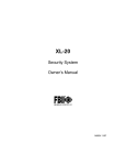
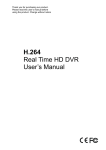
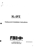
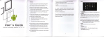
N9466 Rev A 11/B
Technical Manuals Online! - http://www.tech-man.com
Quick Reference
TURN SYSTEM
ON
Check to make sure the system is READY - Green ready light is lit
Enter your four digit user code 0000
The On/Off (Arm) light will light
Exit through a door designated by your installer as an exit/entry door.
TURN SYSTEM
OFF
Enter through a door designated by your installer as an exit/entry door.
Enter your four digit user code 0 0 0
The System On (Arm) light will go out
TURN SYSTEM
q
ON AND STAY INSIDE
Check to make sure the system is READY - Green ready ligfit is l,it
Followed by your user code
I(1
0000
The On/Off (arm) light and the Stay light will both light
REMEMBER: You must turn the system off if you want to open the door or
leave the premises after the exit time has passed.
TURN THE SYSTEM ON: PERIMETER
INSTANT MODE AND STAY INSIDE
SENSORS
Check to make sure the system is READY - Green ready light is lit
followed by ’
followed by your user code
0 0
0
0
The On/Off light, the Instant light and the Stay light will all be on
SMOKE
DETECTOR
Enter your four digit user code
Monitoring
Station
.
RESET
Information
0 0 0 0
.’
:
‘,
Account #
Telephone #
Technical Manuals Online!
http://www.tech-man.com
HC-41- User
Manual - Page 1
I’
,.*
..
Introduction
Congratulations on your decision to protect your home or business with the
HC-41 security system. You have chosen a reliable, state of the art security
system that is remarkably easy to operate. Your system has been
professionally installed by your local Securfty Company who can explain
the specifics of your system. Your system is capable of operating as two
separate areas. Each area can be turned on and off separately and can
have separate user codes assigned. In addition, your system is capable of
integrating both traditional wired security sensors and utilizing radio linked
or “wireless” security sensors. Your Installer will consuftwfth you and decide
what combination of sensors is best for your particular installation.
Keypads are the input and display devices for your securfty system. The
following keypad models can interact with your system. Your Security
Company will suggest the model most appropriate for your premises and
your needs.
XK-108 - A surface mount keypad containing indicator lights for each of
the 8 zones (types of protection) and 2 possible areas . The door covering
the buttons is optional and can be removed. If you are using the wireless
option with your system the XK-108 keypad cannot be used.
XK-708 or XK-716- Surface mount keypads containing indicator lights for
each of the 8 zones (types of protection) and 2 possible areas .
XK-‘ILC-Keypad with a plastic case and a two line English read-out LCD
(liquid crystal display). Status messages for the zones, points and areas
are displayed in simple English.
ZR-440 - Wireless Keypad with no status display. Can onfy be used on
systems that are using the wireless option. Not all options are,available
through the wireless keypad, it should be used with eithe_ran XK-708,or an
XL7LC.
The HC-41 is listed by Underwriters Laboratories for Household Fire and
Burglary applications.
Throughout this manual the following conventions
the keystrokes required to perform the functions..
are used to display
- Button labeled BYPASS
-Button labeled INSTANT
- Button labeled STAY
- Button labeled CODE
0000
- Four digit user code
User Manual
- Page 2
Technical ManualsHC-41
Online!
- http://www.tech-man.com
System Reference
POINT
POINT
ID
ZONE DESCRlPllON
AREA
ID
ZONE DESCRIPTION
1
2
3
4
5
6
7
8
-
-
9
-
-
-
10
-
-
-
-
11
-
-
-
-
12-
-
-
-
-
Entry time
Door
Entry time
Door
AREA
13 ‘14 ‘_
15 -
-
16
-
-
Exit time
Area 1
Area 2
The following SEND HELP ALERTS are programmed into my system. Both
Buttons
must be pressed
at the same time to activate
the alert.
The XK-708 and XK-7LC use the buttonsdescribed on the left.
The XK-108 has buttons below the number keys as described on the right.
BUlTONS
#
DESCRIPTION
*
7 9
13’.
‘<
BirlTONS
Left
Center
Right
Technical Manuals Online!
- http://www.tech-man.com
HC-41 User
Manual - Page 3
USER
ID
ASSIGNED
AUTHORIZED
TO
FOR
Area 1 0
1
(MASTER USER
Area 2 0
Both 0
Area 20
Both
programsall users l-l 6)
2
Area 1 0
q
(MASTER USER programs users 2-15)
3
Area 1 0
Area 20
Both d.
4
Area 1 c]
Area 2 0
Both 0
5
Area 1 0
Area 2 0
Both 0
6
Area 1 0
Area 2 0
Both 0
7
Area 1 0
Area 20
Both 0
8
Area 1 0
Area 2 0
Both 0
9
Area 1 0
Area 2 0
Both 0
10
Area 1 0
Area 20
Both 0
11
Area 1 0
Area20
Both 0
Area20
Both 0
Area 2 0
Both 0
Area 20
Both 0
Area 2 [7
Both 0
12 Pager Alert - Yes 0
No 0
Area1 0
If No
13 Door Strike - Yes 0
No 0
If No
Area 1 0
14 Only Turns System On - Yes [7 No 0
If No
Area 1 0
15 Ambush/Duress Code - Yes 0
If No
I
No q
Area 1 0
*Master User can Add, Change, or Erase other user codes.
Two Area System
- Yes 0
No 0
In a two area system, the keypad area indicator will show which area is
currently being displayed. To switch the display to the other area you press
(Either * or #3, depending on how your installer configured the system.)
The keypad commands you enter wifl only affect the area currently
displayed. If you are not authorized for the other area you can display the
status of that area but you.will not be able to enter commands.
Please keep your manual in a convenient
to it if needed.
location
so you can refer
HC41 User
Manual - Page 4
Technical Manuals Online!
- http://www.tech-man.com
System Operation
Hardwired Keypad
TURNING THE SYSTEM ON
You can turn the Burglar portion of your security system on and off. Before
you turn the system on it must be ready. If you have a protected door open,
or someone is moving by a motion detector the system will not show ready.
in a 2 area system your area indicator will show you which area is active
The system
is ready if the ready light is on or if the display
shows:
Area # will display area 1 or 2 or the area description If programmed.
TURN THE SYSTEM
ON AND LEAVE
Enter your four digit user code 0 00 q
‘The System On (Arm) light will go on or the display will show:
Exit through a door designated by your installer as an exit/entry door. You
must leave within the period-of time known as the exit time. Check the
reference sheet for the time that has been set for your system.
NOTREbY
I’.
If the system is not ready to be am-red the READY’light will be off and the
‘Zone lights will show which zone or zohes are not ready. The zone lights
indicate the following conditions or the display will show as below:
Alarm
Fast Blink
Slow Blink/Low
Slow Pulse
Solid On
Intensity
:
Bypass
Trouble
Not Ready
i :~a
’
”
Example: If the Ready light is not lit and the zone one light is solid on.
An alarm sensor on zone one is not normal. This might mean that a window
is open or someone is walking through a motion sensor. Check all sensors
on zone one and resolve the problem. When all sensors are normal the
Ready light will come on and the zone light will go out.
HC41 User
Manual - Page 5
Technical Manuals Online!
- http://www.tech-man.com
Display shows:
-1
NOT RDY
FRONT DOOR
ZN 01
TO TURN THE SYSTEM
ON - NOT READY
Determine which zone or zones is not ready, resolve the problem and turn
the system on normally. If the problem cannot be resolved’you may bypass
the zone that is not ready. Bypassing should only be done if the problem
on the zone cannot be resolved OR if you intentionally wish to leave the
zone off. Example: you wish to keep the wfndow open for ventilation.,Zones
that are bypassed are not protected when the system is on. See Bypass
for the correct procedure.
”
TURN SYSTEM
ON AND STAY INSIdE
To turn the perimeter portion of your burglar alarm on and move around
freely inside is the STAY mode.
Check to make sure the system is READV; when ready press:
Followed by your user code
pq
If successful the On/Off (arm) light will be lit and the Stay light will also be
lit or the display shows:
q qoo
REMEMBER: You must turn the system off if you want to open the door or
leave the premises after the exit time has, passed.
TURN THE SYSTEM ON: PERIMETER
INSTANT MODE AND STAY INSIDE
SENSORS
In INSTANT STAY mode the perimeter portion of yourburglaralarm system
is on and the time delays are eliminated from your normal entry/exit door(s).
All interior protection is off so you are free to move around inside.
system is READY, when ready press:
followed by
followed by your user code
q q
[7
cl
If successful the On/Off light, the Instant light and the .Stay light will all be
on or the display shows:
W-41 User Manual - Page 6
Technical Manuals Online!
- http://www.tech-man.com
TURN THE SYSTEM
ON: ALL SECURITY
INSTANT
In INSTANT mode all sensors are active and will respond immediately if
violated.
Check to make sure the system is READY, when ready press:
followed by your user code 0 0 q 0
If successful the On/Off light, the Instant light and the INS light will all be on
or the display shows:
BYPASS
Your system can be set up to bypass by Zones (groups of points) or by
individual points of protection. Bypass excludes a zone or point of protection
from the security system until it is unbypasssed. Bypassing can only be
done while the system is turned off.
’ ’
My system is’set up for bypass by Zone - Yes 0 No m
My system is set up for bypass by Point - Yes 0
BYPASS
No 0
BY ZONE
Press the Bypass Button followed by your user code and then the Zone #
(l-8) to be bypassed. Subsequent zones can be bypassed by pressing the
by the zone # within 10 seconds.
0000
‘ZONE
NOTE: Bypassed zones are not protected when the system is turned on.
After the bypass command has been accepted the keypad will sound one
long beep and the zone or zones, bypassed will slowly blink or the display
shows:
NOTE: Temporary users (i.e. baby sitters, housekeepers, etc.) should not
be shown the Bypass procedure.
BYPASS
BY POINT
Press the Bypass Button followed by your user code and then the 2 digit
point # (01-24) to be bypassed. Subsequent points can be bypassed by
pressing the bypass button followed by the point # within a 10 second
NOTE: Bypassed points are not protected when the system is turned on.
After the bypass command has been accepted the keypad will sound one
Technical Manuals Online!
- http://www.tech-man.com
HC41 User
Manual - Page 7
long beep and the point or points bypassed will slowly blink or the display
shows:
NOTE: Temporary users (i.e. baby sitters, housekeepers;etc.) should not
be shown the Bypass procedure.
My system
is set up to automatically
unbypass
any
bypassed zones or points when I turn the system off.
YesO
Noa
If No, you will have to manually unbypass the zone(s) or point(s) you have
bypassed by following the unbypass procedure.
UNBYPASS
Unbypass returns a bypassed zone or point to normal operation.
Unbypass is a repeat of the bypass function.
I)[
q 0[70
ZONE or POINT
After unbypassing the zone display will show the state of the’zones.
TURN THE SYSTEM OFF
When you turn off the system, you are turning ‘off only the burglar portion
of your system, any smoke or heat detectors and panic buttons will remain
on. You must enter through a designated entry door and turn off the system
within the time allowed. You can have different amounts of time for different
entry points. See your system reference sheet for the times established for
your system.
Enter your four digit user code
0000
If no alarms have taken place, the On/Off light (labeled arm) will go off or
the display shows:
If alarms occurred when the system was on , or if a trouble condition exists
they will display on the zone indicator lights as follows:
Alarm
Fast Blink
Slow Blink/Low Intensity
Bypass
Slow Pulse
Trouble
Not Ready
Solid On
or the display shows:
,
l-E-41 User
Manual - Page 6
Technical Manuals Online!
- http://www.tech-man.com
Burglary Alarms will sound a &eady sound through the keypad(s) and fire
alarms will generate a pulsing sound.
Important: If an intrusion has taken place while you were away, do not enter
until the location has been checked. Call for help from a neighbor’s house
and wait for the police.
After you have turned the system off with your user code the message on
display keypads will show:
To clear the display of the alarm or trouble conditions and silence the audible
alert :
again.
Enter your four digit user code 0 0 0 0
USER CODES
ADD OR CHANGE
A USER CODE
Users can be entered or modified directly through the keypad. Your system
can have up to 6 different User Codes. User #l is the Master User and is
the only one allowed to add, or delete other users.
Press the Code button followed by the four digit master user code then the
user # and the new four digit user code. The keypad will beep after each
digit is pressed.
Master User Code User ID
-1
0000
us
New User Code
,, 0000
There is a record sheet provided in the front of this manual to help you plan
and record your users. On this sheet your installer will indicate any special
purpose user codes you may have designated. You may have chosen to
dedicate a user code to send an emergency signal in the case of Ambush
or Duress. You may also have chosen to reserve one user code that is only
allowed to turn the system on, this code will not be able to turn the system
off. In addition door strike and pager alert are special options. It is not
necessary to record the user code that you assign to a user. If a user forgets
their user code follow the change user code procedure for their user ID.
This provides you with a higher level of security. No one can accidentally
discover the list and use someone else’s usercode.
DELETE
A USER CODE
To delete user #3, press the code button followed by the four digit master
user code. then the user # then * to delete.
Master User Code
NO&@
q on0
User ID
3
l
to dele’te
*
e master user, cannot be deleted but it can be changed using the ADD
OR CHANGE U’SER PROCEDURE.
Technical Manuals Online!
- http://www.tech-man.com
HC41 User
Manual - Page 9
TURN SYSTEM ON ONLY (Maid Code)
If you choose to have a code that cannot turn the system off, but can turn
the system on, have your installer program this feature. If programmed,
user ID 14 will have System On capability only and you can issue this code
to a temporary user so they can secure the premises when they leave.
KEYPAD SEND HELP CONDITIONS
Your system can be programmed for 3 separate Send, Help Alerts which
would send an emergency signal to your central station. See ‘System
Reference sheet to see which have been programmed for your.system.
Duress
Your system can be programmed to send an emergency signal to the
Central Station if you are forced to enter the premises. If you choose to
include this feature, User ID 15 is dedicated to this function and must only
be used under a duress circumstance.
Quick On - (Quick Arming) Yes 0
No
q
‘.
If programmed by your installer, QUICK ON, or Quick Arming allows you to
turn the system on to the away mode without user code.. NOTE: Turning
.your system Off always requires a valid User Code.
#
1 To turn both areas on, in a biro area system # 0 # 1
To Quick On in the Stay inside mode Press
$1
,Followed#l
Quick Forced On -
Yes 0
‘.
No 0
If programmed by your installei,Quick Forced On, allows you to turn the
burglar portion of your alarm system on to the away mode bypassing all
zones that are not ready.
# 2 To Quick force on both areas irra two area system # 0 # 2
NOTE: A valid user code is still required to turn the system off.
NOTE:, This feature is disabled on UL installations.
.
Quick On/Quick Off bokh areas - Yes 0
No 0
If programmed by your installer Quick On/Quick Off for both areas, allows
you to turn the burglar portion of your alarm system on to the away mode
or off by pressing # 0 followed by your user code.
# ocloocl
HC41 User
Manual - Page 10
Technical Manuals Online!
- http://www.tech-man.com
Zone/Point Directory Display (English Keypad only)
Display the list of points/zones and their descriptions.
# 4
The points will scroll through the display.
Turn Chime On/Off
Chime is an optional feature that causes the keypad to chime when selected
doors are opened when the burglary protection is off or disarmed.
Only your installer can program a zone for the chime feature, but once
programmed you can turn chime on or off to meet your daily needs. To turn
chime on or off.
#
56
Display Time (English Keypad Only)
To display the system time
Press #.5 1
Display Auto On Time (English Keypad Only)
If your system has been configured to turn itself on automatically at a
specific time each day you can display that time.
#52
Set System Time
System time is necessary if you are using the automatic on feature or if you
are sending periodic test signals to your monitoring station.
To set the time on a indicator light keypad follow this sequence
# 5 3 •~~~
[Hour] [Minute] [Month] [Day] [Year]
Where the hour is a two digit entry 00-23 [Military time] Midnight is 00 Noon
is 12 and 3pm is 15 (Add 12 to each hour after noon).
Minute is (00-59)
Month is (01-l 2)
Day is (01-31)
Year is (00-99)
The sounder will beep after each entry.
English Language Keypads will prompt you for each entry.
Technical Manuals Online!
- http://www.tech-man.com
HC41 User
Manual - Page 11
Set Auto On Time :
To set the automatic system on time, Press #54 your four digit user code
followed by the two digit hour and two digit minute.
# 5 4 00~0
[Hour] [Minute]
Where the hour is a two digit entry 00-23 [Military time] Midnight is 00 Noon
is 12 and 3pm is 15 (Add 12 to each hour after noon).
Minute is 00-59
.
Door Strike
Door Strike is a feature that allows you to use your user code to
electronically unlock doors. It requires special locks and equipment.
# 60000
[Door#]
Door # Description
1
2
:
Door #
3 :
4
Description
..
,.
.’
,
. . .
.’
.;
HC-41 User
Manual - Page 12
Technical Manuals Online!
- http://www.tech-man.com
Keypad Indicators
STAY LIGHT -’ Indicates the system is on with interior points/zones
excluded so you cam move freely inside the premises.
INSTANT LIGHT - Indicates that the exit/entry delay times have been
eliminated any activation will create an instant alarm.
READY LIGHT - When lit, the system is ready to be turned on. When off,
check zone status indicators to see which zone/zones is not ready.
ON/OFF (ARM/DISARM)
LIGHT - When lit, the burglar portion of the
system is on.,When off, the burglar system is off. Blinking LED indicates
communication failure. Check to see if your phones are working.
AC/LOW BATTERY LIGHT-When
lit, your system is running on electricity
(AC power). Whenoff, the system is running on the standby battery. If off,
check to see if the system is plugged in and if so, make sure you have not
blown the fuse or circuit breaker.
, ZONE STATUS INDICATORS - Zone lights display status as follows:
Slow Blink/Low Intensity
Fast Blink
Alarm
Bypass
Slow Pulse Trouble
Solid On
Not Ready
READY.LED - A FLASHING. ready .LED indicates that the system is in the
Installer programming mode. The fire and burglary zones are disabled while
in this mode. Contact your installation company.
FUNCTION BUTTONS - Stay, Instant, Bypass, Code are all used for
system input.
”
XK-108 (Cannot be used
.with wireless system
F
A
P
XK-108 KEYPAD
Technical Manuals Online!
http://www.tech-man.com
HC-41 -User
Manual - Page 13
-
XK-708
XK-7LC uses English language
display instead of status and
zone lights described on
previous page
XK-7LCKEYPAD
SOUNDER - The sounder in the keypad beeps whenever the keypad keys
are pressed. The sounder also beeps when the system is on and you open
a delay door as a warning to remind you to turn the system off. The sounder
will produce fast beeps when a message is received by the central station.
It is important to be careful when turning the system on, because if the
system is not ready and the user code is entered the keypad will beep 4
times showing that there is a problem and that the system baa not accepted
your request.
FIRE PROTECTION - Fire protection is always active and fire conditions
are given a priority..
FIRE ALARM - Audible and Visual Indicators. On LED keypads the
programmed fire zone LED and the ARM LED will blink fast to indicate a
fire alarm. The sounder in the keypad will pulse on and off following the bell
or siren output..
1.
Technical Manuals Online!
http://www.tech-man.com
HC-41 User -Manual
- Page 14
S stem Operation
fv ireless Keypad
The communication
indicator
on the l key will light to
show that the key press has been transmitted.
If the light
does not light, the key press will not be recognized by the
. system.
TURN THE SYSTEM ON
You can turn the Burglar portion of your security system .on and off. Before
you turn the system on it must be ready. If you have a protected door open,
or someone is moving by a motion detector the system will not show ready
TURN THE SYSTEM
ON AND LEAVE
Enter your four digit user code
0 0 0 0
;lJ;Nz;;STEM
ON AND STAY INSIDE
TURN THE SYSTEM
T1MES
ON - STAY INSIDE WITH NO DELAY
TURN THE SYSTEM ON - ALL SENSORS
ACTIVATE IMMEDIATELY
#73
WILL
q unu
QUICK ON
#l
QUICK FORCED
ON
#2
TURN SYSTEM OFF
Enter your 4 digit user code 0 0
q
0
l-C-41 - User
h4anual- Page 15
Technical Manuals Online!
http://www.tech-man.com
BYPASSING (same area keypad)
BYPASS BY ZONE
Enter # 4 followed by 4 digit user code followed by zone #
# 4
q
uun
ZONE#(i-8)
BY PASS BY POINT
Enter # 4 followed by 4 digit user code followed by 2 digit point #
# 4 [7nnn
POINT # (01-24)
QUICK BYPASSING (same area keypad)
BYPASS BY ZONE
Enter # 4 followed by zone #
# 4 ZONE # (l-8)
BYPASS BY POINT
Enter # 4 followed by 2 digit point #
# 4 POINT # (01-24)
SEND HELP CONDITIONS (same area keypad)
.a’.
KEY PAD PANIC
Press # and l together
KEYPAD FIRE
Press in sequence
#81
,‘,
;
KEYPAD AUXILIARY
Press in sequence
#82
NOT AVAILABLE
ON W IRELESS KEYPAD
User code programming
Using l to change areas
Any Quick Commands not Listed in this section
Installer Programming modes
User Manual
.- Page 16
Technical ManualsHC-41~
Online!
- http://www.tech-man.com
Installation
-:
Layout
Eariy waming fire detection ie best achieved by the installation of, fire
detection equ~nata~tio~~
follows:
(Proposed)
r-%if?!t~
Muse.
lhan aw sleaplng a m a smoke dektor
should be
detacmsatuinbe-betweenthesleepingaR3aandthefestoflhe
NOTEz Refer to KF.PA
874 Appenda 81.1 through B-10.
pfovtdedto protect
in the diagram a + represents a smoke detector.
Preparation of an evacuation plan is of prime importance in fire prevention.
Establish a houaehoid or business emergency evacuation plan to be
foiiowed in the event of a fire.
1. Evaluate possible escape routes from your h o m e or business.
2. Select 2 escape routes from each room.
3. Rooms on the second floor should have a rope ladder (make sure it
reaches the ground) or fire escape.
4. Draw a rough sketch of your escape plan so everyone is familiar with it. .’
5. Practice your escape pian to make sure everyone knows what to do.
6. Eetabiii a meeting piace outside where everyone will meet.
7. Advise the iocai fire authority that you have installed a fire alarm system.
6. When the fire aiarm signals, LEAVE IMMEDIATELY.
Do not stop for
belongings.
9. if a fire occurs. test the door. if hot, use your alternate route. if the door
ia cool, brace your shoulder against it and open it cautiously. Shut the door
to help prevent the fire and smoke from spreading. Crawl through smoke
holding your breath.
10. Contact the F ire Department from a neighboring house or business.
11. Everyone, including neighbors, should be familiar with your F ire and
Burglary audible aiarm sounders.
Fire AlarmSound
is:
Burglar Alarm Sound is:
HC41 User
Manual - Page 17
Technical Manuals Online!
- http://www.tech-man.com
System Limitations.
LIMITATIONS OF THIS ALARM SYSTEM
While this system is an advanced design security system, it does not offer guaranteed
protection against burglary, fire, or other emergency. Any alarm system, whether commercial
or residential, is subject to compromise or failure to warn for a variety of reasons. For example:
@ Intruders may gain access through unprotected openings or have the technical
sophistication to bypass an alarm sensor or disconnect an alarm warning device.
@ Intrusion detectors (e.g. passive infrared detectors), smoke detectors, and many other
sensing devices will not work, without batteries, or if the batteries are not put in property.
Devices powered solely by AC will not work if their AC power supply is cut off for any reason,
I :.
however briefly.
@ Signals sent by wireless transmitters may be blocked or reflected by metal before they reach
the alarm receiver. Even if the’signal path has been recently checked during a weekly test,
blockage can occur if a metal object is moved into the path.
@ A user may not be able to reach a panic or emergency button quickly enough.
Q While smoke detectors have played a key role.in reducing’ residential fire deaths in the
United States, they may not activate or provide early warning for a variety of reasons in as..
many as 35% of all fires according to data published by the FederafEmergencyManagement
Agency. Some of the reasons smoke detectors used in conjunction with the System may not
work are as follows: Smoke detectors may not, sense fires that start where smoke cannot reach
the detectors, such as in chimneys, in walls, or roofs, or on the other.side of closed doors.
Smoke detectors also may not sense a fire on another level of a residence or building. A
second floor detector, for example, may not sense a first floor or basement fire. Moreover,
smoke detectors have sensing limitations. No smoke detector can sense every kind of fire
every time. In general, detectors may not always warn about fires caused by carelessness
and safety hazards like smoking in bed, violent explosions, escaping gas, improper storage
of flammable materials, overloaded electrical circuits, children playing with matches, or arson..
Depending on the nature of the fire and/or the location of the smoke detectors, the detector,
even if it operates as anticipated, may not provide sufficient warning to allow all occupants to
escape in time to prevent injury or death.
@ Passive Infrared Motion Detectors can only detect Intrusion within the designed ranges as
diagrammed in their Installation Manual. Passive Infrared Detectors do not provide volumetric
area protection. They do create multiple beams of protection, and Intrusion can only be
detected in unobstructed areas covered by the beams. They cannot detect motion or intrusion
that takes place behind walls, ceilings, floors, closed doors, glass partitions, glass doors or
windows. Mechanical tampering, masking, painting or spraying, of any material on the mirrors,
windows or any part of the optical system can reduce their detection ability. Passive Infrared
Detectors sense changes in temperature; however, as the ambient temperature of the
protected area approaches the temperature range of 90 degrees to 150 degrees Fahrenheit,
the detection performance can decrease.
‘23Alarm warning devices such as sirens, bells or horns may not alert people or wake up
sleepers who are located on the other side of closed or partly open doors. If warning devices
sound on a different level of the residence from the bedrooms, then they are less likely to
waken or alert people inside the bedrooms. Even persons who are awake may not hear the
warning if the alarm is muffled by noise from a stereo, radio, air conditioner, other appliances,
or by passing traffic. Finally, alarm warning devices, however loud, may not warn
hearing-impaired people or waken deep sleepers.
@ Telephone lines needed to transmit alarm signals from a premises to a central monitoring
station may be out of service or temporarily out of service. Telephone lines are also subject
to compromise by sophisticated intruders.
User Manual
- Page 18
Technical Manuals HC41
Online!
- http://www.tech-man.com
@ However, even if the system responds to the emergency as intended occupants may have
im@kknttfmeb
protect themsehres from the emergency situation. In the case of a monitored
atann system, authorittes may not respond appropriately.
8 This eqdpnmt, fike other electrfcal de&es, is subject to component failure. Even though
this equipment is designed to last as long as 10 years, the electronic components could fail
atanythle.
Themoet cotntnm cause of an alarm system not functioning when an fntrusion or fire occurs
in inadequate maintenance. This alarm system should be tested weekly to make sure all
-working
pmperfy.
ktaging an alarm system may make one eligible for lower insurance rates, but an alarm
system is not a substiMe for tnsurance. Homeowners, property owners and renters should
confinue by act prudentfy In protecting themselves and continue to insure their lives and
Propetty.
We ccntfnue to develop new and improved pmtectlon devices. Users of alarm systems owe
H to themseks and their loved ones to learn about these developments.
HC41 User Manual - Page 19
Technical Manuals Online!
- http://www.tech-man.com
Glossary
Small green’light between the center buttons on the keypad. When lit, the
system is running on electricity; when not lit, the system is running on the backup battery.
ALARM: Sound from keypad or other horn/siren indicates a burglar alarm, fire alarm or other
condition you should be alerted to.
ARMED: See ON/OFF
AWAY: A system setting that protects the premises while it is unoccupied. All burglary sensors
are active.
BURGLARYIFIRE:
The two major functions of a Security System. Fire protection is always
on and cannot be turned off. The Burglary sensors protect against unauthorized entry into
your premises. The Burglary protection can be turned on and off and programmed for special
levels of access and notification.
BYPASS FEATURE: The Bypass Feature allows you to exclude a selected zone/point or
zones/points from the burglar alarm protection.
BYPASS BUTTON: A button on the keypad used to activate the Bypass Feature.
CENTRAL STATION: Signal Monitoring Center contacted by your Security System over the
telephone and/or other communication channels when alarms are activated if your system is
programmed to communicate alarms off site. The Central Station will follow their procedures
and your instructions for contacting the proper authorities when a signal is received.
CHIME FEATURE: An optional feature that causes the keypad to chime for one second when
selected doors are opened when the burglary protection is off or disarmed. Once programmed
by your installer you can turn chime on and off with #56.
DISARMED: See ON/OFF.
DURESS: Duress is a system feature the you may have programmed into your system. If
someone should force you to turn your system off, you would use the special Duress user
code and the system would turn off and it would also send a silent duress emergency to the
Central Station so they could respond appropriately.
ENTRY DELAV: The period of time allowed between opening a designated entry/exit door
and turning off the alarm system before the system will register an alarm condition. Thls is
determined at the time of installation. Your system supports two entry times allowing you to
have a different length of time for different doors.
EXIT DELAY: The period of time allowed between turning the system on and leaving through
a designated exit/entry door. This is determined at the time of Installation.
HYBRID CONTROL: An Alarm control that supports more than one alarm sensor connection
technology. In the case of your system those technologies are standard hardwfre connections
and Radio Frequency ‘Wireless’ transmissions.
INTERIOR ZONE: An interior zone is a group of points that protect the interior of your premises.
You may want to turn the perimeter portion of your system on while leaving the interior zones
off allowing you to move freely inside, opening interior doors and passing by motion detectors
without causing an alarm.
KEYPAD: A Keypad is your link into your system. It displays alarm and trouble messages,
shows faulted zones and allows you to turn the system on/off by using the buttons. Your system
will have one or more keypads.
MONITORING STATION: Signal Monitoring Center contacted by your Security System over
the telephone and/or other communication channels when alarms are activated if your system
is programmed to communicate alarms off site. The Monitoring Stration, sometimes called a
Central Station, will follow their procedures and your instructions for contacting the proper
authorities when a signal is received.
AC INDICATOR:
HC-41 User Manual - Page 20
Technical Manuals Online! - http://www.tech-man.com
ON/OFF: These terms refer to the burglary portion of your security system. There are several
levels of operation which allow you to protect part of your premises while you remain inside.
FW eensom and other emergency and environmental conditions are always active and ready
and are not affected in any yay by turning the burglary portion of your Security System on or
off. Armed, a term that is sometfmes used means system on and Disarmed means system
off. See ON-INSTANT; ON-STAY and STAY.
ON/OPP INDICATOR: Red light in the upper portion of the keypad labeled Armed. When lit,
some part of the burgfar alarm system is on; when not lit, the burglary portion of the system
Isoff.
OKSTAY: A system setting that turns on the perimeter protection of the building but allows
movement tluwghout the lnslde.
PANlC BUllON:
A push button which allows you to slgnai the Central Station that you need
fmmedfate assistance. Your system has programmable Keypad Send Help Alerts which can
alsO.%3~eSPanicbuttoW.
POINT: A potnt of pmtectfon = an alarm sensing device.
RECElVERz Radio Frequency Signal Receiver that translates the RF signals from your
wit&es afam~ sensors into information that your HC-42 Alarm Control understands..
PERlMETER,ZONE
A perimeter zone is a group of points that protect the exterior of your
pmmlses Your outslde doors end windows would be programmed as a perimeter zone.
SENSOR: The actual alamt sensor, detector or device installed to detect an Intrusion, fire, or
envtnmmemal problem. Examples indude: door contacts, window contacts, motion sensors,
g&se break sensors. smoke detectors, rate of rfse heat detectors, temperature sensors,
lbdhater
sensors, and tabon monoxide gas detectors.
SILENT CONDITION: Most types of alarms and troubles alert you with the keypad sounder
and the strens. home, or speakers located in your premises. The intent is to advise you of the
alarm or trouble and allow you to respond promptly. The audible sounds also let an intruder
been detected and will hopefully scare them away. In some
know ‘that they’have
dmm&anme.
an audible alarm might put your life in danger and so those alarms are
programmed as silent conditions. For an example see DURESS.
SYSTEM Your Securtty System is composed of three main parts: 1) the Control Panel which
hmdfons as the system brain and the link to the Monitoring Agency (Central Station), 2) the
Keypad(s) which pmvkle you with system status and allow you input commands, 3) Security
Sensors such as door and window contacts, motfon sensors, smoke detectors and other
sensora as required to detect Intrusion, fire and other conditions as needed for your premises.
W
A Radio Frequency transmitter that sends radio signals from your wireless
alarm sensing devkes to your wireless receiver.
USEB CODE: A user code fs a 4 digit code which ls required to operate the system. The
system supports up to 6 separate user codes. The system supports one master user who can
acWd&te other usar codes. Two of the user codes may be dedicated to special functions as
deftned by your alarm company at the time of installation. (See the User Code List near the
fKUltOfthiSttlEltlUal)
Instead of using a wire to connect an alarm sensing device your system is capable
of supportfng @elees connections using a Radio Frequency Recetver and Transmitters.
ZONE: A,zone ls a collectfon of sensors with common characteristics grouped together for
your opemtfng ccnvenience. The system will support 8 zones or groupings.
WIRELESS:
HC-41 -User
Manual - Page 21
Technical Manuals Online!
http://www.tech-man.com
Federal Communications’
Commissidin (FCC) Statement
This equipment has been tested to FCC requirements and has been found acceptable for use.
The FCC requires the following statement for your information:
This equipment generates and uses radio frequency energy and tf not installed and used
properly, that is. in strict accordance with the manufacturer’s instructions, may cause
interference to radio and television reception. It has been type tested and found to comply
with the limits for a class B computing device in accordance with the spedftcattons in Subpart
J Part 15 of FCC Rules, which are designed to provide reasonable protection against such
interference in a residential installation. However, there is no guarantee that interference will
not occur in a particular installation. If this equipment does cause interference to radio.or
television reception, which. can be determined by. turning the equipment on, the user is
encouraged to try and correct the interference by one or more of the following measures:
@ If using en indoor antenna, have a quality outdoor antenna installed.
@ Reorient the receiving antenna until interference is reduced or elirnfnated.
@ Move the receiver away from any wire runs to the control/communicator.
@ Plug the control/communicator into a different outlet so that it and the receiver are on !
different branch circuits.
If necessary, the.user should consult the dealer or an experienced radio/television technician
for additional suggesuons.
,’
The user or installer may Rnd the following booklet prepared by the Federal’CdmmunicaUons
Commission helpful: ‘Interference Handbook?.
This booklet is available from the U.S. Government Printing Off@ Washington, DC 20402.
Stock No., 004-000-00450-7.
The user shall not make any changes or modifications to the equipment unless author&d by’
the installation Instructions or User’s Manual. Unauthorized changes or modifications,could
void the user’s authority to operate the equipment.
TELEPHONE
OPERATIONAL
PROBLEMS
In the event of telephone operational problems, disconnect the control by removing the plug
from the RJ31X wall jack. We recommend that your certified installer demonstrate
disconnectfng the phones on installation of the system. Do not disconnect the phone
connection inside the control/communicetor. Doing so will result in the loss of your phone lines.
If the regular phone works correctly after the control/communicator has been disconnected
from the phone lines, the control/communicator has a problem and should be returned for
repair. If upon disconnecuon of the control/communicator, there is sUll a problem on the line,
notify the telephone company that they have a problem and request prompt repair servfce.
The user may not under any circumstances (in or out of warranty) attempt any service or
repairs to the system. It must be returned to the factory or an authorized service agency for
all repairs. SYSTEM TESTING
This control unit was manufactured under rigid quality standards and complies with all UL
requirements for its intended use. Maintenance is best performed by your installing company
with trained servtce personnel.
User Manual
- Page 22
Technical Manuals HC-41
Online!
- http://www.tech-man.com
\
Limited Warranty
Fke Burglary Instruments, Inc.,. a subsidiary of Pkway Corporation, and Pitway Corporation, its
divisions. subsidiades and affiltates (‘Seller’), 149 Eileen Way, Syosset, New York 11791, warrants
its securfty equipment (the ‘product’) to be free from defects in material and workmanship for five
years from date of original purchase, under normal use and service. Seller’s obligation Is limited to
repairing or repladng. at its optfon, free of charge for parts, labor, or transportation, any product
proved to be defective in materials or workmanship under normal use and service. Seller shall have
no obligation under this warranty or otherwise if the product is altered or improperly repaired or
servfced by anyone other than the Seller. In case of defect, contact the security professtonal who
installed and maintains your security equipment or the Seller for product repair.
i
,
,
1
1
1
1
,
This five year Lfmfted Warranty is In lieu of all other expressed warrantfes, obligations or liabilities.
THERE ARE NO EXPRESS WARRANTIES, WHICH EXTEND BEYOND THE FACE HEREOF. ANY
IMPLIED WARRANTIES, OBLIGATIONS OR LIABILITIES MADE BY SELLER IN CONNECTION
WITH THIS PRODUCT, INCLUDING ANY IMPLIED WARRANTY OF MERCHANTABILITY, OR
FlTNESS FOR A PARTICULAR PURPOSE OR OTHERWISE, ARE LIMITED IN DURATION TO A
PERIOD OF AVE YEARS FROM THE DATE OF ORIGINAL PURCHASE, ANY ACTION FOR
BREACH OF ANY WARRANTY, INCLUDING BUT NOT LIMITED TO ANY IMPLIED WARRANTY
OF MERCHANTABILITY, MUST BE BROUGHT WlTHlN 60 MONTHS FROM DATE OF ORIGINAL
PURCHASE. IN NO CASE SHALL SELLER BE LIABLE TO ANYONE FOR ANY CONSEQUENTIAL
OR INCIDENTAL DAMAGES FOR BREACH OF THIS OR ANY OTHER WARRANTY, EXPRESS
OR IMPLIED, OR UPON ANY OTHER BASIS OF LIABILITY WHATSOEVER, EVEN IF THE LOSS
OR DAMAGE IS CAUSED BY THE SELLERS OWN NEGLIGENCE OR FAULT. Some states do
not allow limitation on how long an implied warranty fasts or the exclusion or ltmitation of incidental
or consequentfal damages, so the above limitation or exdusfon may not apply to you.
,
I
Seller does not represent that the product may not be compromised or circumvented; that the product
will prevent any personal injury or property loss by burglary, robbery, fke or otherwise; or that the
product will in all cases provkle adequate waming or protection. Buyer understands that a property
installed and maintained alarm may only reduce the risk of a burglary, robbery, fire or other events
occuntng without providing an alarm, but it is not Insurance or a guarantee that such will not occur
or that there will be no personal injury or property loss as a result. CONSEQUENTLY, SELLER
SHALL HAVE NO LIABILITY FOR ANY PERSONAL INJURY, PROPERTY DAMAGE OR OTHER
LOSS BASED ON A CLAIM THE PRODUCT FAILED TO GIVE WARNING. HOWEVER, IF SELLER
IS HELDLIABLE,WHETHER DIRECTLY OR INDIRECTLY, FOR ANY LOSS OR DAMAGE ARISING
UNDER THIS LIMITED WARRANTY OR OTHERWISE, REGARDLESS OF CAUSE OR ORIGIN,
SELLER’S MAXIMUM LIABILITY SHALL NOT IN ANY CASE EXCEED THE PURCHASE PRICE
OF THE PRODUCT, WHILE SHALL BE THE COMPLETE AND EXCLUSIVE REMEDY AGAINST
SELLER. This warranty gives you specfftc legal rtghts, and you may also have other rights which
vary from state to state. No increase of alteration, written or verbal, to this warranty is authorized.
Technical Manuals Online! - http://www.tech-man.com
,
\
/
,
1
,’
)’
It is recommended
that you test your system
following
procedure:
System Test
once a week using
the
NOiE:‘If your system is monitored, contact your Central Station before you
perform this test.
1. Turn your Security System on.
2. Wait until your exit time is over and them activate the system by opening
a protected zone. (For example: a window or,door).
3. Confirm that the alarm sounding device (bell or siren) sounds. If your
system is connected to a central station the keypad will sound the ringback
tone to confirm that the signal was received.
4. Turn the Security System off.
5. Call the Central Station to tell them you are done testing.
BAlTERY
TEST
It is recommended that you test your Battery once a month. In order to test
your backup/standby battery, the following procedure should be followed:
1. Unplug the transformer from the AC outlet by removing the.restraining
screw which secures the transformer to the wall. (Note: the screw is not
present on the models sold in Canada.)
2. Observe that the AC,indicator light on the keypad goes off.
.3. Activate your alarm by performing the above SYSTEM TEST. Remember
to contact your Central Station if your system is monitored.
4. Plug the transformer into the AC outlet and secure with the restraining
. screw. (Note: the screw is not present on the models sold in’canada;)
The National Fire Protective .Association publishes a standard for fire
warning equipment (NFPA publication #74). Further information can be
obtained by contacting: NFPA Public Affairs Dept., Batterymarch Park,
Quincy, MA. 02269.
If you have any further questions about the operation of yoursystem,
alarm company.
1.
,
..
please contact your
/
d
‘.
HC41 User- http://www.tech-man.com
Manual - Page 24
Technical Manuals Online!
Technical Manuals Online! - http://www.tech-man.com
Technical Manuals Online! - http://www.tech-man.com