1
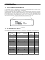
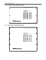
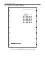
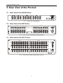
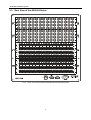
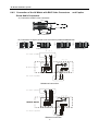
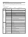
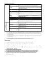
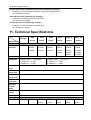
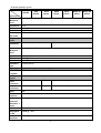
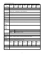
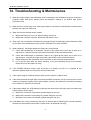
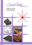
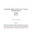
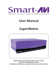
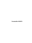
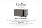
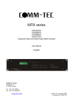
CREATOR Electronics
AV Matrix Switchers System
User Manual
Please read this manual carefully before using this product.
AV Matrix Switcher System
Notice:
:
This AV Matrix Switchers User Manual takes example of the Matrix model
AV16X16. It can be used as user’s manual of other AV matrix switcher models.
This manual is only an instruction for operators, not for any maintenance usage.
This manual is copyright CREATOR Corporation. All rights reserved. No part of
this publication may be copied or reproduced without the prior written consent of
CREATOR Corporation.
All product function is valid till 2010-12-31
1
AV Matrix Switcher System
! Safety Operation Guide
In order to ensure the credibility use of the product and the user’s safety, please comply with the
following items during installation and maintenance:
The system must be earthed properly. Please do not use two blades plugs and ensure the alternating
power supply ranged from 100v to 240v and from 50Hz to 60Hz.
Do not put the switcher in a place of too hot or too cold.
To avoid any damage by over heat, please keep the working environment good in ventilation to radiate
the heat when running the switcher.
The switchers should be turned off when in rainy and humid days or nonuse for a long time,
The alternating power supply line should be disconnected with the power socket during the following
operation.
A. Take out or reinstall any component of the switcher
B. Disconnect or re-connect any connector of the switcher
Please do not attempt to maintain and uncover the switcher for there is a high-voltage component
inside and the risk of the electric shock.
Do not splash any chemical product or liquid on or near the equipment.
2
AV Matrix Switcher System
Contents
1. INTRODUCTION.............................................................................................................................5
1.1 ABOUT AV MATRIX SWITCHER SYSTEM ....................................................................... 5
1.2 AV MATRIX SWITCHER MODELS ..................................................................................... 5
2. PACKING OF THE PRODUCT.......................................................................................................6
3. INSTALLATION ..............................................................................................................................6
4. FRONT VIEW OF THE PRODUCT ................................................................................................7
4.1 FRONT VIEW OF THE AV0404 SERIES .......................................................................... 7
4.2 FRONT VIEW OF THE AV8 SERIES .................................................................................. 7
4.3 FRONT VIEW OF THE AV16 SERIES................................................................................ 7
4.4 FRONT VIEW OF THE AV24, 32 SERIES........................................................................ 8
4.5 FRONT VIEW OF THE AV48, 64 SERIES........................................................................ 8
4.6 FRONT VIEW OF THE AV96, 128 SERIES ..................................................................... 9
5. REAR VIEW OF THE PRODUCT.................................................................................................10
5.1 REAR VIEW OF THE AV4X4 SERIES ............................................................................ 10
5.2 REAR VIEW OF THE AV8 SERIES .................................................................................. 10
5.3 REAR VIEW OF THE AV16 SERIES................................................................................ 10
5.4 REAR VIEW OF THE AV24, 32 SERIES ........................................................................ 11
5.5 REAR VIEW OF THE AV48,64 SERIES ......................................................................... 12
5.6 REAR VIEW OF THE AV96,128 SERIES ...................................................................... 13
6. EXTERNAL CONNECTION .........................................................................................................14
6.1 INTRODUCTION OF THE INPUT AND OUTPUT CONNECTORS ................................. 14
6.2 CONNECTION OF RS-232 COMMUNICATION PORT ................................................. 14
6.2.1
Connection with Control Systems .................................................................. 14
3
AV Matrix Switcher System
6.2.2
Connection with Computer ............................................................................. 14
6.3 HOW TO CONNECT WITH THE INPUT AND OUTPUT TERMINALS .......................... 15
6.4 HOW TO CONNECT WITH THE AV DEVICES ................................................................ 15
6.4.1 Connection of the AV Matrix with RCA Connectors ........................................ 15
6.4.2 Connection of the AV Matrix with BNC Video Connectors ..... and Captive Screw
Audio Connectors
16
7. OPERATION OF THE CONTROL PANEL ...................................................................................17
7.1 FRONT PANEL DESCRIPTION .......................................................................................... 17
7.1.1
Front Panel Description of AV0404 .......................................................... 17
7.1.2
Front Panel Description of AV1616 .......................................................... 17
7.1.3
Front Panel Description of Additional Buttons for AV32, AV48, AV64, AV96,
AV128 ........................................................................................................................ 18
7.2 COMMAND FORMAT OF THE SWITCHING OPERATION............................................. 19
7.3 EXAMPLES OF OPERATION .............................................................................................. 19
8. USAGE OF THE REMOTE CONTROLLER (OPTIONAL
ACCESSORY) ...................20
9. OPERATION OF THE SWITCHER APPLICATION .....................................................................21
9.1 INTRODUCTION OF SWITCHER 2.0............................................................................ 21
9.1.1
9.1.2
About the Application ..................................................................................... 21
Starting the Application ................................................................................... 21
9.2 FUNCTIONS OF THE APPLICATION ................................................................................. 21
9.2.1
9.2.2
9.2.3
9.2.4
9.2.5
9.2.6
9.2.7
Interface Description ...................................................................................... 22
Description of SYSTEM Tab ........................................................................... 22
Description of KEYBOARD Tab...................................................................... 23
Description of Auto Tab .................................................................................. 23
Description of Custom Code Tab.................................................................... 24
Description of Code Group Tab ...................................................................... 25
Description of Send/receive Code List Tab..................................................... 26
10. COMMUNICATION
PROTOCOL AND COMMAND CODES ..28
11. TECHNICAL SPECIFICATIONS ................................................................................................31
12. TROUBLESHOOTING & MAINTENANCE ................................................................................34
4
AV Matrix Switcher System
1. Introduction
1.1
About AV Matrix Switcher System
AV series Matrix switcher is a high-performance professional video and audio signal switcher that can
be used for cross switching of multi computer and audio signal.
AV series switcher mostly apply in broadcasting TV engineering, multi-media meeting room, big screen
display engineering, television education, command control center or other fields. It provides power-fail
locale protection function, LCD displaying, shortcut selecting and saving function. With RS232 interface,
it can be worked with PC, remote control system and any other far-end control system devices.The user
manual takes AV1616 as the example; other models can take reference from it too.
CREATOR
HIGH RESOLUTION AV MATRIX SWITCHERS
S YS T E M M ONTIO R
POWER
ACTIVE
NETWORK
SENSOR
AV
VIDEO
AUDIO
1
2
3
4
ENTER
All
5
6
7
8
9
0
/
SAVE
RECALL
CANCEL
STATUS
AV CROSSPOINT MATRIX SWITCHERS
F 1-1 AV 1616
1.2
AV Matrix Switcher Models
According to different situation and users, the AV series can be classified into the following models:
Specifications
A/V Input
A/V Output
RS232
Interface
LCD
Display
MATRIX AV0404
4
4
√
×
MATRIX AV0802
8
2
√
√
MATRIX AV0804
8
4
√
√
MATRIX AV0808
8
8
√
√
MATRIX AV1604
16
4
√
√
MATRIX AV1608
16
8
√
√
MATRIX AV1616
16
16
√
√
MATRIX AV2408
24
8
√
√
MATRIX AV2416
24
16
√
√
MATRIX AV2424
24
24
√
√
MATRIX AV3208
32
8
√
√
MATRIX AV3216
32
16
√
√
MATRIX AV3224
32
24
√
√
MATRIX AV3232
32
32
√
√
MATRIX AV4832
48
32
√
√
MATRIX AV4848
48
48
√
√
Models
5
AV Matrix Switcher System
Specifications
A/V Input
A/V Output
RS232
Interface
LCD
Display
MATRIX AV6432
64
32
√
√
MATRIX AV6448
64
48
√
√
MATRIX AV6464
64
64
√
√
MATRIX AV9664
96
64
√
√
MATRIX AV9696
96
96
√
√
MATRIX AV12864
128
64
√
√
MATRIX AV12896
128
96
√
√
MATRIX AV128128
128
128
√
√
Models
2. Packing of the Product
AV Matrix Switcher
Professional matrix switc her series
System monitor
Pow er
Ac t ive
Net wo rk
Rem ote
VG A
AV
Video
Audio
Enter
1
2
3
4
5
6
7
8
Sav e
Rec all
F1
F2
F3
F4
Hi gh resolution AV/VGA m atri x swichers
RS-232 Communication Cord
Power Supply Cord
CD with Application SWITCHER 2.0
User Manual and Quality Guarantee
3. Installation
AV matrix switchers adopt metal shell and can be stacked with other device. Moreover, they are
rack-mountable enclosure and can be installed in the standard 19” rack.
HIGH RESOLUTION AV MATRIX SWITCHERS
SYSTEM MONITOR
PO WER
AC TIVE
NETWO RK
SEN SO R
AV
VIDEO
AUDIO
1
2
3
4
ENTER
All
5
6
7
8
9
0
/
SAVE
RECALL
CANCEL
STATUS
AV CROSSPOINT MATRIX SWITCHERS
项目 编号:
F 3-1 Installing the AV matrix switcher in the standard 19” rack
6
AV Matrix Switcher System
4. Front View of the Product
4.1
Front View of the AV0404 Series
CREATOR
AV CROSSPOINT MATRIX SWITCHERS
F 4-1 Front view of the AV0404
4.2
Front View of the AV8 Series
HIGH RESOLUTION AV MATRIX SWITCHERS
SYSTEM MONTIOR
POWER
ACTIVE
NETWORK
SENSOR
AV
VIDEO
AUDIO
1
2
3
4
5
6
7
8
9
0
/
ENTER
All
SAVE
RECALL
CANCEL
STATUS
CREATOR
AV CROSSPOINT MATRIX SWITCHERS
F 4-2 Front view of the AV0802, AV0804, AV0808
4.3
Front View of the AV16 Series
CREATOR
HIGH RESOLUTION VIDEO MATRIX SWITCHERS
SYSTEM MONTIOR
POW ER
A CTIVE
N ETWORK
SENSOR
AV
VIDEO
AUDIO
1
2
3
4
ENTER
All
5
6
7
8
9
0
/
SAVE
RECALL
CANCEL
STATUS
VIDEO CROSSPOINT MATRIX SWITCHERS
F 4-3 Front view of the AV1604, AV1608, AV1616
7
AV Matrix Switcher System
4.4
Front View of the AV24, 32 Series
HIGH RESOLUTION VIDEO MATRIX SWITCHERS
SYSTEM MONTIOR
P OWER
VIDEO
AUDIO
ENTER
2
3
PROGRAM
4
5
7
8
9
0
/
END
AC TIV E N ETWORK S ENSOR
ALL
SAVE
THROUGH RECALL
CLOSE
STATUS
LOCK
DEMO
CANCEL
CREATOR
VIDEO CROSSPOINT MATRIX SWITCHERS
F 4-4 Front view of the AV2408, AV2416, AV2424, AV3208, AV3216, AV3224, AV3232
4.5
Front View of the AV48, 64 Series
HIGH RESOLUTION VIDEO MATRIX SWITCHERS
SYSTEM MONTIOR
POWE R
VIDEO
AUDIO
ENTER
2
3
PROGRAM
4
5
7
8
9
0
/
END
ACTIV E N ETWORK SEN SOR
ALL
SAVE
THROUGH RECALL
CLOSE
STATUS
LOCK
DEMO
CANCEL
CREATOR
VIDEO CROSSPOINT MATRIX SWITCHERS
F 4-5 Front view of the AV4832, AV4848, AV6432, AV6448, AV6464
8
AV Matrix Switcher System
4.6
Front View of the AV96, 128 Series
HIGH RESOLUTION AV MATRIX SWITCHERS
SYSTEM MONTIOR
POWER
VIDEO
AUDIO
ENTER
2
3
PROGRAM
4
5
7
8
9
0
/
END
ACTIVE NETWORK SENSOR
ALL
SAVE
THROUGH RECALL
CLOSE
STATUS
LO CK
DEMO
CANCEL
CREATOR
AV CROSSPOINT MATRIX SWITCHERS
F 4-6 Front view of the AV9664, AV9696, AV12864, AV12896, AV128128
9
AV Matrix Switcher System
5. Rear View of the Product
5.1
Rear View of the AV4X4 Series
RS-232
L
L
R
R
CAUTION
D O NOT O PEN
RISK OF ELECTRIC SH OC K
AC100V-240V 50/60Hz
F 5-1 Rear view of the AV0404
5.2
Rear View of the AV8 Series
VIDEO INPUT
VIDEO OUTPUT
RS-232
MODEL:
2
3
4
5
6
7
8
1
2
3
4
AUDIO INPUT
5
6
7
8
6
7
8
AUDIO OUTPUT
AC100V-240V
50/60Hz
1
CAUTION
1
2
3
4
5
6
7
DO NOT OPEN
RISK OF ELECTRIC SHOCK
8
1
2
3
4
5
F 5-2 Rear view of the AV0802,AV0804,AV0808
Rear View of the AV16 Series
2
3
4
OUTPUTS
5
6
7
8
1
2
3
4
5
6
7
8
VIDEO
9
10
1
2
3
12
13
14
15
16
9
10
4
5
6
7
8
1
2
3
12
13
14
15
16
4
5
6
7
8
R
RS-232
VIDEO
ETHERNET
INPUTS
1
R
AUDIO
AUDIO
9
10
1
2
3
12
13
14
15
16
9
10
4
5
6
7
8
1
2
3
12
13
14
15
16
4
5
6
7
8
L
L
AUDIO
AUDIO
9
10
12
13
14
15
16
9
10
12
13
14
15
AC100V-240V
50/60Hz
5.3
16
CAUTION
DO NOT OPEN
RISK OF ELECTRIC SHOCK
F 5-3 Rear view of the AV1604,AV1608, AV1616
10
AV Matrix Switcher System
Rear View of the AV24, 32 Series
CAUTION
RS-232
ETHERNET
DO NOT OPEN
RISK OF ELECTRIC SHOCK
AC100V-240V
50/60Hz
5.4
F 5-4 Rear view of the AV2424,AV3232
11
AV Matrix Switcher System
5.5
Rear View of the AV48,64 Series
1
2
3
4
5
6
7
8
9
10
11
12
13
14
15
16
17
18
19
20
21
22
23
24
25
26
27
28
29
30
31
32
33
34
35
36
37
38
39
40
41
42
43
44
45
46
47
48
49
50
51
52
53
54
55
56
57
58
59
60
61
62
63
64
1
2
3
4
5
6
7
8
9
10
11
12
13
14
15
16
17
18
19
20
21
22
23
24
25
26
27
28
29
30
31
32
33
34
35
36
37
38
39
40
41
42
43
44
45
46
47
48
49
50
51
52
53
54
55
56
57
58
59
60
61
62
63
64
L
1
R
L
2
R
L
3
R
L
4
R
L
5
R
L
6
R
L
7
R
L
8
R
L
9
L
17
R
L
18
R
L
19
R
L
20
R
L
21
R
L
22
R
L
23
R
L
24
R
L
25
L
33
R
L
34
R
L
35
R
L
36
R
L
37
R
L
38
R
L
39
R
L
40
R
L
L
49
R
L
50
R
L
51
R
L
52
R
L 53
R
L
54
R
L
55
R
L
56
R
L
1
R
L
2
R
L
3
R
L
4
R
L
5
R
L
6
R
L
7
R
L
8
L
17
R
L
18
R
L
19
R
L
20
R
L
21
R
L
22
R
L
23
R
L
L
33
R
L
34
R
L
35
R
L
36
R
L
37
R
L
38
R
L
39
R
L
49
R
L
50
R
L
51
R
L
52
R
L 53
L
54
R
L
55
R
R
L 10
R
L
11
R
L
12 R
L
13 R
L
14 R
L
15 R
L
16 R
R
L 26
R
L
27
R
L
28 R
L
29 R
L
30 R
L
31 R
L
32 R
41
R
L 42
R
L
43
R
L
44 R
L
45 R
L
46 R
L
47 R
L
48 R
L
57
R
L 58
R
L
59
R
L
60 R
L
61 R
L
62 R
L
63 R
L
64 R
R
L
9
L 10
R
L
11
R
L
12 R
L
13 R
L
14 R
L
15 R
L
16 R
24
R
L
25
R
L 26
R
L
27
R
L
28 R
L
29 R
L
30 R
L
31 R
L
32 R
L
40
R
L
41
R
L 42
R
L
43
R
L
44 R
L
45 R
L
46 R
L
47 R
L
48 R
L
56
R
L
57
R
L 58
R
L
59
R
L
60 R
L
61 R
L
62 R
L
63 R
L
64 R
R
R
F 5-5 Rear view of the AV4832,AV4848,AV6432,AV6448,AV6464
12
AV Matrix Switcher System
5.6
Rear View of the AV96,128 Series
5
10
1
6
16
11
F 5-6 Rear view of the AV9664,AV9696,AV12864,AV12896,AV128128
13
AV Matrix Switcher System
6. External Connection
6.1
Introduction of the Input and Output Connectors
According to different type of matrix, computer signal I/O interface are make up of Channel 4,Channel
8 for RCA terminals; Channel 16,Channel 24,Channel 32,Channel 48,Channel 64,Channel 96,
Channel 128 BNC female terminals, audio signal I/O terminals are make up of Channel 2,Channel 4,
Channel 8,Channel 16,Channel 24,Channel 32,Channel 48,Channel 64,Channel 96,Channel
128 3.8mm captive screw connectors(or RCA terminals). The channel number of AV1616 signal I/O
terminals are form Channel 1 to Channel 8 and Channel 9 to Channel 16 (form left to right, display in
two rows), The interfaces are video terminals (BNC), audio left state terminals (white RCA), audio right
state terminals (red RCA). Please refer to shell silk-screen figure about other types of interface.
6.2
Connection of RS-232 Communication Port
Except the front control panel, the AV matrix switcher can be control by far-end control system or
through the Ethernet control via the RS-232 communication port.
This RS-232 communication port is a female 9-pin D connector. The definition of its pins is as the table
below.
Pin
RS-232
Description
1
N/u
Not used
2
Tx
Transmit data
3
Rx
Receive data
4
N/u
Not used
5
Gnd
Signal ground
6
N/u
Not used
7
N/u
Not used
8
N/u
Not used
9
N/u
Not used
6.2.1
Connection with Control Systems
With the RS-232 port, the AV matrix switchers can be control by several kinds of control systems.
6.2.2
Connection with Computer
When the switcher connects to the COM1 or COM2 of the computer with control software, users can
control it by that computer.
To control the switcher, users may use the application SWITCHER 2.0 in the supplied CD or develop
their own control software with the protocol and control codes. Please refer the details in Chapter
10.Communication Protocol and Command Codes.
Host of matrix switcher
RS-232
Computer for controlling
14
AV Matrix Switcher System
F 6-1 Connection between AV matrix switcher and the computer
6.3
How to Connect with the Input and Output Terminals
The AV matrix switchers may take DVD players, video tape recorders, camcorders, cable TV and video
showing platform as their input signal source, and projectors, RP TVs, video tape recorders and
amplifiers as their output signal destinations.
F 6-2 Connection of AV matrix switcher system
6.4
6.4.1
How to Connect with the AV Devices
Connection of the AV Matrix with RCA Connectors
Tip (+)
Video Out
A/V input equipments
Audio Out
L
R
(Out put ports)
Output
Input
Video
AV matrix switcher
Sleeve ( )
Audio L
Audio R
RCA Connector
A/v output equipment
L
Video In
R
Audio In
Input port
F 6-3 Connection of the AV matrix with RCA
15
AV Matrix Switcher System
6.4.2
Connection of the AV Matrix with BNC Video Connectors
Screw Audio Connectors
and Captive
A)Connection of BNC video connectors
Tip (+)
Sleeve ( )
BNC Connector
B)Connection of captive screw audio connectors (unbalanced/balanced)
Tip
Tip
Sleeve
Sleeves
Tip
Tip
Sleeve
Unbalanced Input
Unbalanced Output
Tip
Ring
Sleeves
Tip
Ring
Sleeves
Tip
Ring
Balanced Input
输 出
A/V input equipment
Tip
Ring
Balanced Output
端 子
Video Out
Audio Out
L
R
(Input ports)
(Output ports)
Output
Input
Video
AV matrix swicther
L
R
L
R
L
R
L
R
A/V output equipment
L
Video In
R
Audio In
Input ports
Unbalanced connection
输
出
端
子
Video Out
A/V input equipment
L
R
(Input ports)
(Output ports)
Output
Input
Video
L
R
L
R
L
A/V output equipment
L
Video In
Balanced connection
16
R
R
L
R
AV Matrix Switcher System
7. Operation of the Control Panel
7.1
7.1.1
Front Panel Description
Front Panel Description of AV0404
“AV”
“VIDEO”
“AUDIO”
“1,2,3,4”
7.1.2
AV synchronal button: To transfer video and audio signal synchronously by the switcher
Example: To transfer both the video and the audio signals from input channel No.3 to
output channel No.4.
Operation: Press buttons in this order “3”, “AV”, “4””.
Video button: To transfer only video signals from input channel to output channel
Example: To transfer video signals from input channel No.3 to output channel No.4.
Operation: Press buttons in this order “3”, “VIDEO”, “4”.
Audio button: To transfer only audio signals from input channel to output channel
Example: To transfer audio signals from input channel No.2 to output channel No.3.
Operation: Press buttons in this order ““2”, “AUDIO”, “3””.
I/O Keypads: Keys to select I/O channels.
Example: To transfer input channel No.3 to output channel No.1
Operation: Press buttons in this order : “3” in IN PUT area, “1” in OUT PUT area.
Front Panel Description of AV1616
CREATOR MATRIX
VGA8X8
V2.0
“1,2,3,4”
“AV”
“VIDEO”
“AUDIO”
“/”
“END”
“ENTER”
“ALL”
LCD display: Real time monitor of the operations and status
Keypad: Keys to select I/O channels and save/recall preset commands
AV synchronal button: To transfer video and audio signal synchronously by the switcher
Example: To transfer both the video and the audio signals from input channel No.3 to
output channel No.6.
Operation: Press buttons in this order “3”, “AV”, “6”, “END”, “ENTER”
Video button: To transfer only video signals from input channel to output channel
Example: To transfer video signals from input channel No.3 to output channel No.10.
Operation: Press buttons in this order “3”, “VIDEO”, “1”, “0”, “END”,“ENTER”
Audio button: To transfer only audio signals from input channel to output channel
Example: To transfer audio signals from input channel No.12 to output channel No.6.
Operation: Press buttons in this order “1”, “2”, “AUDIO”, “6”, “END”,“ENTER”
Break button: To break different channels in a command
Example: To transfer video and audio signals from input channel No.1 to output
channel No.2,13,6 at the same time
Operation: Press buttons in this order “1”, “AV”, “2”, “/”, “1”,“3”, “/”, “6”, “END”,
“ENTER”
Ending command button: To finish inputting a command
Performance button: To perform a command after inputting it
All button: To transfer an input channel to all output channels or switch off all the output
17
AV Matrix Switcher System
“SAVE”
“RECALL”
“CANCEL”
“STATUS”
7.1.3
channels
Example1: To transfer video and audio signals from input channel No.7 to all output
channels
Operation: Press buttons in this order “7”, “ALL”
Note: This command need not follow by “END” & “ENTER”
Example2: To transfer all input signals to the corresponding output channels
respectively. In another word, to switch to this status: 1->1, 2->2, 3->3,
4->4LL16->16.
Operation: Press buttons in this order “ALL”, “1”
Example3: To switch off all the output channels
Operation: Press buttons in this order “ALL”, “2”
Save button: To save the present operation to a preset command
Example: To save the present operation to the preset command No.2
Operation: Press buttons in this order “SAVE”, “2”
Note: There are altogether 10 preset commands ranged from No.0 to No.10.
Recall button: To recall the preset command
Example: To recall the preset command No.2
Operation: Press buttons in this order “RECALL”, “2”
Cancel button: To return to the standby status without performing any command
Example: To cancel the input instructions “1”, “AV”, “2”, “END”
Operation: Just press button“CANCEL” after the above inputs
Inquiring status button: To inquire the present status
Example1: To inquire the status of output channel No.7
Operation: Press buttons in this order “7”, “STATUS”
Example2: To inquire the status of all the output channels one by one
Operation: Press only the button “STATUS”
Front Panel Description of Additional Buttons for AV32, AV48, AV64, AV96,
AV128
“UNDO”
Undo button: To resume to the status before the command just performed
“PROGRAM” Group programming button: To define, recall and clear a group of output channel
Example1: To group the output channels No.1,2,3,4,5 under the Group1
Operation: Press buttons in this order “1”, “Program”, “Program”, “1”, “2”, “3”, “4”, “5”
Example2: To transfer signals from input channel No.1 to Group2
Operation: Press buttons in this order “1”, “Program”, “2”
Example3: To clear the output channels under Group1
Operation: Press buttons in this order “1”, “Program”, “0”
Note: Please clear the group to be set before grouping it.
“←”
Backspace button: To backspace the latest input button
“THROUGH” Through button: To transfer the signals directly to the corresponding output channels
Example: To transfer the signals from input channels No.1,2,3 to their corresponding
output channels
Operation: Press buttons in this order “1”, “/”, “2”, “/”, “3”, “THROUGH”
“CLOSE”
Close button: To switch off the output channels
18
AV Matrix Switcher System
Example: To switch off the output channels No.1,2
Operation: Press buttons in this order “1”, “END”, “2”, “END”, “CLOSE”
“LOCK”
Lock button: To lock buttons on the front control panel by pressing it for 3 seconds
Note: When the control panel is being locked, the switcher still can be control via the
RS232 port. To unlock it, a password is needed.
“DEMO”
7.2
Demo button: To demonstrate the commands one by one every 3 seconds
Command Format of the Switching Operation
With the front control panel, the switcher could be control directly and rapidly by pressing the buttons
under below format.
“Input Channel”+“Switching Mode”+“Output Channel 1”+“/”+“Output Channel 2”+“END”+“ENTER”
“Switching Mode”: “AV”, “Audio”, “Video”
“Input Channel”: Fill with the number of input channel to be controlled
“Output Channel”: Fill with the number of output channels to be controlled
7.3
Examples of Operation
Example 1:
:To transfer video and audio signals from input channel No.1 to output channel
No.3,4
1
2
3
4
Input Command:
1,Press the button for input channel number“1”
Display feedback on LCD: “1” for the input
channel
1
AV
Video
Audio
2,Press the button for switching mode “AV”
Display feedback on LCD: “B” for the switching
mode of video and audio (“A” for the switching
mode of audio only; “V” for the switching mode
of video only)
Input Command:
1B
2
3
4
3,Press the button for the first output channel
number “3”
Display feedback on LCD: “3” for the first output
channel
Input Comm and:
1B3
0
/
END
4,Press the break button“/”
Display feedback on LCD: “ , ” for a break
between two channels in a command
Input Comm and:
1B3,
5,Press the button for the second output channel
number “4”
19
AV Matrix Switcher System
2
3
Display feedback on LCD: “4” for the second
output channel
Input C omm and:
4
1B3,4
0
/
6,Press the button“END” to finish the command
Display feedback on LCD: “.” for the end of a
command
Input Comm and:
END
1B3,4.
ENTER
RECALL
7. Press the button “ENTER” to perform this
command
Display feedback on LCD: “Switch OK” for the
successful performance of switching
1B3,4.
Switc h OK
Example 2: To inquire the status on the output channel No.4
Operation: Press buttons in this order “4”, “STATUS”
2
3
4
RECALL CANCEL
VID EO: 3
AUDIO: 2
STATUS
4
4
Display feedback on LCD: The video signal of output channel No.4 is transferred from the input channel
No.3 and the audio signal is from the input channel No.2
8. Usage of the Remote Controller
(Optional
Accessory)
With the optional infrared remote controller, the matrix switcher
could be control remotely. Because the function buttons on the
remote controller are the same with the ones on the front control
panel, the remote controller shares the same control operation and
command format with the control panel. Please refer the details in
Chapter 7 Operation of the Control Panel.
20
AV Matrix Switcher System
9. Operation of the Switcher Application
9.1
Introduction of SWITCHER 2.0
SWITCHER 2.0 is a matrix switcher control application compatible with switchers with different input
and output channels.
9.1.1
About the Application
SWITCHER 2.0 is developed for matrix system test and control. Its running condition is as below:
Operating System: Window98/2000/NT
Memory: At least 32M
Space in hard disk: At least 10M
CD-ROM
COM Port
9.1.2
Starting the Application
Firstly, connect the matrix switcher and computer via their RS232 ports with the cord supplied in the
package. (Please refer to 6.2.2 Connection with Computer for details).
Secondly, turn on the power of the matrix switcher and computer.
Thirdly, run the application SWITCHER 2.0 at the computer.
9.2
Functions of the Application
According to practical needs, user can select and operate at different function tabs such as SYSTEM,
AUTO, KEYBOARD, CUSTOM CODE, CODE GROUP and SEND/RECEIVE CODE LIST.
The interface of main window is as below:
21
AV Matrix Switcher System
F 9-2
9.2.1
The interface of main window
Interface Description
In the right hand of the main window, there are 256 buttons
standing for the 256 output channels. When clicking on the
button, say output 1, the dialogue OutPort 1 like the graph at
right will come up.
“SIGNAL”: Select the switching mode among “AV”, “VIDEO”
and “AUDIO”
“INPUT A/V PORT”: Select an input A/V channel
“INPUT AUDIO PORT”: Select an input audio channel
9.2.2
Description of SYSTEM Tab
F 9-2
Startup
Choose SYSTEM Tab from the main window. (F 9-2)
Description
“CONNECTION MODE”: Select the communication mode between “COM” or “TCP/IP”
“COM”: Select a COM port to control the switcher (if select the “TCP/IP” as the communication mode,
this sub-page will appear as an IP input blank for the address of switcher)
“Set Password”: Set the password for the control panel on the Matrix (The password should be an 8
digits number)
“Unlock Keyboard”: Unlock the keyboard of the control panel on the Matrix
22
AV Matrix Switcher System
9.2.3
Description of KEYBOARD Tab
Startup
Choose KEYBOARD Tab from the main window. (F 9-3)
F 9-3
Keyboard tab
Description
Because the function buttons on this tab are the same with the ones on the front control panel, it shares
the same control operation and command format with the control panel. Please refer the details in
Chapter 7 Operation of the Control Panel.
9.2.4
Description of Auto Tab
Startup
Choose the Auto Tab from the main window. (F 9-4)
23
AV Matrix Switcher System
F 9-4
Auto Tab
Description
This function tab is used to test the matrix switcher after connecting it to all the input and output devices.
For example, to test the function of an AV64X32 matrix switcher, the Auto Tab is set as below after
finishing all the connection.
Switch Mode: “AV”
INPUT: From 1 to 64
OUTPUT: From 1 to 32
Delay: 1000ms (1 second)
When click on the button “START” to perform this test, the matrix switcher will:
Transfer the signals from the input channel No.1 to the output channel No.1-32;
Transfer the signals from the input channel No.2 to the output channel No.1-32;
LL
Transfer the signals from the input channel No.64 to the output channel No.1-32;
This switching test will perform in this way one by one every one second until the test is over.
9.2.5
Description of Custom Code Tab
Startup
Choose the Custom Code Tab from the main window. (F 9-5)
24
AV Matrix Switcher System
F 9-5
Custom Code Tab
Description
Format: Select the format of command codes between ASCII and HEX (For the format details, please
refer to the Chapter 10. Communication Protocol and Command Codes)
Help: Click this button to read the explanation of commands
Send: Click this button to send out the command
For example, to transfer the video and audio signals from the input channel No.1 to the output channel
No.7, and the audio signals from the input channel No.2 to the output channel No.4, just perform the
several steps below.
1. Select the “ASCII” as the command codes format;
2. Input the command codes “1B7.2A4.” at the blank of Codes;
3. Click the button “Send” to perform it.
9.2.6
Description of Code Group Tab
Startup
Choose the Code Group Tab from the main window. (F 9-6)
25
AV Matrix Switcher System
F 9-6
Code Group Tab
Description
New: To new a group of preset commands
Open: To open a group of preset commands
Save: To save the present group of preset commands
Execute: To execute a selected preset command or a selected group of preset commands
Clear: To clear the feedback window
Add Codeltem: To add another new group of preset commands
Edit: To edit the User’s name (User), the Group’s name (Description), the Code of command (Code)
Delete: To delete the selected group
9.2.7
Description of Send/receive Code List Tab
Startup
Choose the Send/receive Code List Tab from the main window. (F 9-7)
26
AV Matrix Switcher System
F 9-7 Send/receive Code List Tab
Description
Send List window: A send list of command code
Received List window: A feedback list from the switcher
Clear: To clear the two lists
27
AV Matrix Switcher System
10. Communication Protocol and Command Codes
With this command system, the application Switcher 2.0 is able to control and operate the AV Matrix
remotely.
Communication protocol:
Baud rate: 9600
Command
Types
Data bit: 8
Stop bit: 1
Command Codes
Parity bit: none
Functions
System Command
Operation Command (CREATOR2.0 Command
System)
/*Type;
Inquire the models information.
/+xxxxxxxx;
Rewrite the password of the control panel on the Matrix. The
new password, xxxxxxxx, should be an 8 digits number.
/%Lock;
Lock the keyboard of the control panel on the Matrix.
/%Unlock;
Unlock the keyboard of the control panel on the Matrix.
/:BellOff;
Turn off the buzzer.
/:BellOn;
Turn on the buzzer.
/^Version;
Inquire the version of software
/~CREATOR20;
Switch to the CREATOR2.0 command system.
/:MessageOff;
Block the COM port feedback information, only show “SWITCH
OK!”
/:MessageOn;
Receive the COM port feedback information, show the detail
information for all the operation.
/%Backlightxxx;
Setting the delay time for background light. The unit is minute,
ranging form 001 to240 min. (30 min for default setting)
[x1]All.
Transfer signals from the input channel [x1] to all output
channels
All#.
Transfer all input signals to the corresponding output channels
respectively.
All$.
Switch off all the output channels.
[x1]#.
Transfer signals from the input channel [x1] to the output
channel [x1].
[x1]$.
Switch off the output channel [x1].
[x1] V[x2].
Transfer the video signals from the input channel [x1] to the
output channel [x2].
[x1] V[x2],[x3],[x4].
Transfer the video signals from the input channel [x1] to the
output channels [x2], [x3] and [x4].
[x1] A[x2].
Transfer the audio signals from the input channel [x1] to the
output channel [x2].
[x1] A[x2],[x3],[x4].
Transfer the audio signals from the input channel [x1] to the
output channels [x2], [x3] and [x4].
[x1] B[x2].
Transfer both the video and the audio signals from the input
channel [x1] to the output channel [x2].
28
AV Matrix Switcher System
Compatible Command
System
[x1] B[x2],[x3],[x4].
Transfer both the video and the audio signals from the input
channel [x1] to the output channels [x2], [x3] and [x4].
[x1]P[x2].
Transfer signals from the input channel [x1] to all the output
channels in group [x2].
[x1]PP[x2],[x3],[x4].
Group the output channels [x2], [x3] and [x4] under the group
[x1].
S[x].
Inquire the output channels in Group[x].
Status[x1].
Inquire the input channel to the output channel [x1].
Status.
Inquire the input channel to the output channels one by one.
Save[Y].
Save the present operation to the preset command [Y]. [Y]
ranges from 0 to 9.
Recall[Y].
Recall the preset command [Y].
Clear[Y].
Clear the preset command [Y].
[X1]*[X2]!
Transfer both the video and the audio signals from the input
channel [x1] to the output channel [x2].
[X1]*[X2]$
Transfer the audio signals from the input channel [x1] to the
output channel [x2].
[X1]*[X2]%
Transfer the video signals from the input channel [x1] to the
output channel [x2].
[X1]*[X2]&
Transfer the video signals from the input channel [x1] to the
output channel [x2].
Note:
1. [x1], [x2], [x3] and [x4] are the symbols of input or output channels ranged according to the
model of the matrix switcher. If the symbols exceed the effective range, it would be taken as a
wrong command.
2. In above commands, “[”and “]” are symbols for easy reading and do not need to be typed in
actual operation.
3. Please remember to end the commands with the ending symbols “.” and “;”.
Detail Examples:
1、
、 Transfer signals from an input channel to all output channels: [x1]All.
Example: To transfer signals from the input channel No.3 to all output channels
Run Command: “3All.”
2、
、 Transfer all input signals to the corresponding output channels respectively: All#.
Example: If this command is carried out on a AV 16X16 matrix switcher, the status of it will be: 1->1,
2->2, 3->3, 4->4LL16->16.
3、
、 Switch off all the output channels: All$.
Example: After running this command, there will be no signals on all the output channels.
4、
、 Transfer signals from an input channel to the corresponding output channel: [x]#.
Example: To transfer signals from the input channel No.5 to the output channel No.5.
Run Command: “5#.”
29
AV Matrix Switcher System
Example: To transfer signals from the input channel No.1,2,3,4 to the corresponding output
channel No.1,2,3,4.
Run Command: “1,2,3,4#.”
6,Switch off an output channel: [x]$.
Example: To switch off the output channel No.5.
Run Command: “5$.”
Example: To switch off the output channel No.1,2,3,4.
Run Command: “1,2,3,4$.”
7,Switch video signals command: [x1] V[x2].
Example: To transfer the video signals from the input channel No.3 to the output channel No.5.
Run Command: “3V5.”
Example: To transfer the video signals from the input channel No.3 to the output channel
No.8,9,12.
Run Command: “3V8,9,12.”
8,Switch audio signals command: [x1] A[x2].
Example: To Transfer the audio signals from the input channel No.10 to the output channel
Run Command: “10A2.”
Example: To transfer the audio signals from the input channel No.10 to the output channel
No2,20,30,40.
Run Command: “10A2,20,30,40.”
9,Switch both video and audio signals synchronously: [x1] B[x2].
Example: To transfer both the video and the audio signals from the input channel No.120 to the
output channel No.12,13,15.
Run Command: “120B12,13,15.”
10,Transfer signals to group channels: [x1]P[x2].
Example: After the command “2PP1,3,5,7.” was carried out, the command “1P2.” would transfer
signals from the input channel No.1 to all output channels in Group2 (1,3,5,7). If [x2] was filled
with “0”, this command will clear the Group[x1]. Please clear the group to be set before grouping
it.
11,Group channel command: [x1]PP[x2],[x3],[x4].
Example: To group the output channels No.1,3,5,7 under the Group2.
Run Command: “2PP1,3,5,7.”
Notes: In this command, the maximum value of [x1] equals to the maximum output channels the
matrix switcher has. To new a Group[x1], the command is “[x1]P0.[x1]PP[x2],[x3],[x4].”. To
expand the Group[x1], the command is “[x1]PP[x7],[x8],[x9].”. Each output channel belongs the
only group claims it the latest.
12,Inquire the output channels in Group[x]: S[x].
Example: To inquire the output channels in Group1.
Run Command: “S[1]”
13,Inquire the input channel to the output channel [x]: Status[x].
Example: To inquire the input channel to the output channel No.23.
Run Command: “Status23.”
14,Inquire the input channel to the output channels one by one: Status.
Example: To inquire the input channel to the output channels one by one
Run Command: “Status.”
30
AV Matrix Switcher System
15,Save the present operation to the preset command [Y]: Save[Y].
Example: To save the present operation to the preset command No.7.
Run Command: “Save7.”
16,Recall the preset command [Y]: Recall[Y].
Example: To recall the preset command No.5.
Run Command: “Recall5.”
17,Clear the preset command [Y]: Clear[Y].
Example: To clear the preset command No.5.
Run Command: “Clear5.”
11. Technical Specifications
Series
AV8
Series
AV0404
Specifications
AV16
Series
AV24
Series
AV32
Series
AV48, 64
Series
AV96, 128
Series
Video
Models
included
AV0404
Gain
0 dB
Bandwidth
100MHz (-3dB) , fully loaded
0 -10MHz:≤+/- 0.1dB
0 -30MHz:≤+/- 0.5dB
Cross
sum
-50dB @ 5 MHz, -45dB @ 10 MHz
talk
AV0802
AV0804
AV0808
Differential
phase I/0S
<1.28°,3.58MHz
Differential
phase error
0.1%, 3.58-4.43MHz
Differential
gain error
0.1°, 3.58-4.43MHz
Maximum
transfer
delay
5nS(±1nS)
Switching
speed
200 ns (Max)
Signal type
Composite video
AV1604
AV1608
AV1616
AV2408
AV2416
AV2424
AV3208
AV3216
AV3224
AV3232
AV4832
AV4848
AV6432
AV6448
AV6464
AV9664
AV9696
AV12864
AV12896
AV128128
150MHz (-3dB) , fully loaded
0 -10MHz:≤+/- 0.1dB
0 -30MHz:≤+/- 0.5dB
Input video
Connector
RCA
RCA
BNC
female
BNC
female
31
BNC
female
BNC
female
BNC
female
AV Matrix Switcher System
Series
AV0404
Specifications
AV8
Series
AV16
Series
Maximum/
Minimum
level
Analog signals: 0.5V ~ 2.0V p-p
Impedance
75 Ω
Echo loss
-30dB@5MHz
Genlock
0.3V-0.4Vp-p
Max error in
DC offset
15mV
AV24
Series
AV32
Series
Output
video
Connector
RCA
BNC female
Maximum/
Minimum
level
Analog signals: 0.5V ~ 2.0V p-p
Impedance
75 Ω
Echo loss
-30dB@5MHz
DC offset
±5mV (Maximum)
Transition
type
Vertical interval
Sync signal
Input/outpu
t signals
NTSC 3.58,NTSC4.43,PAL,SECAM
Audio
signal
Input
connector
RCA
RCA
3.8mm with screw , 5 pole
Output
connector
RCA
RCA
3.8mm with screw , 5 pole
Gain
0dB
Frequency
respond
20 Hz ~ 20 kHz,
General
harmonic
distortion +
noise
0.03% @ 1 kHz (under rating voltage)
S/N
>90dB
Segregatio
n rate
>80dB @ 1 kHz
Y/C
interferer
<-80dB @ 1 kHz, fully loaded
32
AV48, 64
Series
AV96, 128
Series
AV Matrix Switcher System
Series
AV8
Series
AV0404
Specifications
AV16
Series
AV24
Series
CMRR
>75dB @: 20 Hz ~ 20 kHz
Signal
Stereo ,balanced /unbalanced
Impedance
Input:>10 kΩ(balanced /unbalanced)
Output:50 Ω (unbalanced), 100 Ω(balanced)
Maximum
input level
+19.5dBu, (balanced /unbalanced)
Gain error
±0.1dB @20 Hz ~ 20 kHz
Max output
level
+19.5dBu, (balanced /unbalanced)
AV32
Series
AV48, 64
Series
AV96, 128
Series
Control
type
Serial
control port
RS-232, 9-pin FD connector
Baud rate
and
protocol
Baud rate: 9600 Data bit: 8 Stop bit: 1 Parity bit: none
Serial
control
poling
protocol
2 = TX, 3 = RX, 5 = GND
Ethernet
Connector
RJ-45 Female(Optional accessory)
Protocol
TCP/IP
Speed
Full/half-duplex 10/100M
Control
application
Switch 2.0
Features
Power
supply
100VAC ~ 240VAC, 50/60 Hz, universal international power supply
Temperature
Storing and operating temperature: -20° ~ +70°C
Humidity
Storing and operating humidity: 10% ~ 90%
Size
485(L)X24
5(W)
X50mm(H
)
485(L)X24
5(W)
X100mm(
H)
485(L)X24
5(W)
X150mm(
H)
485(L)X24
5(W)
X285mm(
H)
485(L)X24
5(W)
X285mm(
H)
485(L)X26
5(W)
X465mm(
H)
485(L)X26
5(W)
X920mm(
H)
Weight
1.8kg
3.5kg
4.6 kg
9.0 kg
9.0 kg
16.8 kg
29.5kg
MTBF
30,000 hours
Quality
guarantee
1 year free guarantee
33
AV Matrix Switcher System
12. Troubleshooting & Maintenance
1)
When the output image in the destination device connected to the AV Matrix has ghost, such as the
projector output with ghost, please check the projector’s setting or try another high quality
connection cord.
2)
When there is a color losing or no video signal output, it may be the unmatched AV connector order
between the input and output end.
3)
When the remote controller doesn’t works:
A. Maybe the battery is run out of, please change a new one.
B. Maybe the controller is broken, please ask the dealer to fix it.
4)
When user can not control the AV Matrix by computer through its COM port, please check the COM
port number in the software and make sure the COM port is in good condition.
5)
When switching , the beeper beeps but without any output image:
A. Check with oscilloscope or multimeter if there is any signal at the input end. If there is no
signal input, it may be the input connection cord broken or the connectors loosen.
B. Check with oscilloscope or multimeter if there is any signal at the output end. If there is no
signal output, it may be the output connection cord broken or the connectors loosen.
C. Please make sure the destination device is exactly on the controlled output channel
D. If it is still the same after the above checking, it may be something wrong in the switcher.
Please send it to the dealer for fixing.
6)
If the POWER indicator doesn’t work and there is no display on LCD or no respond to any
operation, please make sure the power cord connected well.
7)
If the output image is interfered, please make sure the system is earthed well.
8)
If the static becomes stronger when connecting the BNC connectors, it may be due to the incorrect
earthing of the power supply, Please earth it again correctly, and otherwise it would bring damage
to the switcher or shorten its natural life.
9)
If the beeper beeps, the LCD displaying normally and there is also returning code, but without any
output image or audio output.
A. Maybe A/V connection cord broken, please change a new one.
B. Maybe the connection cord cutting-out, please change a new one.
C. May be the connection cord broken, please change a new one.
10) If the Matrix can not be controlled by the keys on the front panel, RS232 port or remote controller,
the host may has already been broken. Please send it to the dealer for fixing.
34