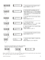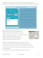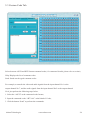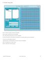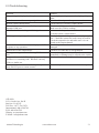
1
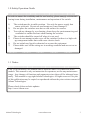
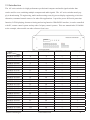
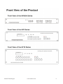
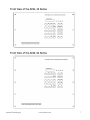
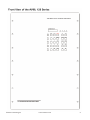
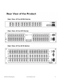
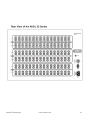
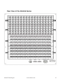
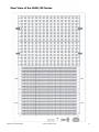
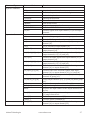
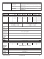
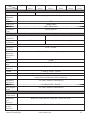
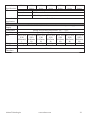
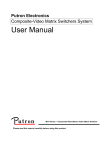
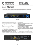
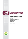
AV SWITCHER USER GUIDE
AT-AV0404 to AV128128
Atlona Technologies www.atlona.com
1
Contents
1.0 Safety Operation Guide......................................................................3
1.1 Notice.................................................................................................3
2.0 Introduction........................................................................................4
2.1 Installation..........................................................................................5
3.0 Connector Types...............................................................................14
3.1 Connecting the AV Switcher.............................................................15
4.0 Operation Controls for AV0404.......................................................16
4.1 Operation Controls for AV1616.......................................................17
4.2 Additional Controls for AV32, AV48, AV64, AV96, AV128.............19
4.3 Remote Control Operation................................................................21
5.0 Operation of Application Software...................................................21
5.1 Keyboard Tab...................................................................................23
5.2 Auto Tab...........................................................................................23
5.3 Custom Code Tab.............................................................................24
5.4 Code Group Tab...............................................................................25
5.5 Send / Recieve Code List Tab..........................................................26
6.0 RS-232 Operation.............................................................................26
7.0 Technical Specifications....................................................................28
8.0 Troubleshooting................................................................................31
Atlona Technologies www.atlona.com
2
1.0 Safety Operation Guide
***************************************************************
In order to ensure the credibility and the user’s safety, please comply with the following items during installation, maintenance and operation of the switch.
1)
2)
3)
4)
5)
6)
7)
The switch must be in stable position. Use only the power supply that
comes with unit. Do not use an alternate as it may damage it.
Do not place the switcher near hot or cold surfaces or sources.
To avoid any damage by over heating, please keep the environment in good ventilation to radiate the heat when running the switcher.
The switcher should be turned off when it is not used.
Please do not attempt to take cover off the switcher for there is a high-volt age component inside that could cause electric shock.
Do not splash any liquid or chemical on or near the equipment.
Please make sure all the wiring are in working condition and are not cut or damaged.
1.1 Notice
*******************************************************************
This VGA Switchers User Manual can be used for other VGA matrix switcher
models. This manual is only an instruction for operators, not for any maintenance
usage. Any changes of functions and parameters since then will be informed separately. This manual is copyright Atlona Technologies. All rights reserved. No part
of this publication may be copied or reproduced without the prior written consent of
Atlona Technologies.
Please check Atlona website updates.
http://www.Atlona.com
Atlona Technologies www.atlona.com
3
2.0 Introduction
The AV series switcher is a high-performance professional computer and audio signal switcher that
can be used for cross switching multiple computer and audio signals. The AV series switcher mostly apply in broadcasting TV engineering, multi-media meeting room, big screen display engineering, television
education, command control center or for other like applications. It provides power-fail locale protection
function, LCD displaying, shortcut selecting and saving function. With RS232 interface, it can be controlled
with PC, remote control system and any other 3rd party control systems. This user manual takes VGA0808
as the example; other models can take reference from it too.
Specifications
Models
MATRIX AV0404
MATRIX AV0802
MATRIX AV0804
MATRIX AV0808
MATRIX AV1604
MATRIX AV1608
MATRIX AV1616
MATRIX AV2408
MATRIX AV2416
MATRIX AV2424
MATRIX AV3208
MATRIX AV3216
MATRIX AV3224
MATRIX AV3232
MATRIX AV4832
MATRIX AV4848
MATRIX AV6432
MATRIX AV6448
MATRIX AV6464
MATRIX AV9664
MATRIX AV9696
MATRIX AV12864
MATRIX AV12896
MATRIX AV128128
A/V Input
A/V Output
RS232 Interface
LCD Display
4
8
8
8
16
16
16
24
24
24
32
32
32
32
48
48
64
64
64
96
96
128
128
128
4
2
4
8
4
8
16
8
16
24
8
16
24
32
32
48
32
48
64
64
96
64
96
128
√
√
√
√
√
√
√
√
√
√
√
√
√
√
√
√
√
√
√
√
√
√
√
√
×
√
√
√
√
√
√
√
√
√
√
√
√
√
√
√
√
√
√
√
√
√
√
√
Atlona Technologies www.atlona.com
4
2.1 Installation
The VGA Switchers can be easily rack mounted using the rack mount ears located in the front of the unit.
Secure the Switch with standard rack-hole screws. It is recommended to leave a 1U space between the units
to have easy access for installation of the cables. When connecting the cables make sure all cables are connected correctly if not it could cause color loss or will not output a display signal.
Packaging Includes
•
•
•
•
•
•
VGA Matrix Switcher
RS-232 Communication Cord
Power Supply Cord
CD with Application SWITCHER 2.0
User Manual and Quality Guarantee
Remote Control
Atlona Technologies www.atlona.com
5
Atlona Technologies www.atlona.com
6
Atlona Technologies www.atlona.com
7
Atlona Technologies www.atlona.com
8
Atlona Technologies www.atlona.com
9
Atlona Technologies www.atlona.com
10
Atlona Technologies www.atlona.com
10
Atlona Technologies www.atlona.com
12
Atlona Technologies www.atlona.com
13
3.0 Connector Types
The AV matrix swticher uses 2 types of Video Connectors for 4 Channel and 8 Channel RCA terminals are
used. For 16 Channel, 24 Channel, 32 Channel, 48 Channel, 64 Channel, 96 Channel, 128 Channel BNC female terminals are use. Audio signal I/O terminals make up of 2 Channel, 4 Channel, 8 Channel, 16 Channel, 24 Channel, 32 Channel, 48 Channel, 64 Channel, 96 Channel 128 Channel with 3.8mm captive screw
connectors(or RCA terminals). The AV1616 switcher signal I/O terminals are form Channel 1 to Channel
8 and Channel 9 to Channel 16 (form left to right, display in two rows), The interfaces are video terminals
(BNC), audio left state terminals (white RCA), audio right state terminals (red RCA). The AV switcher can
also be controlled via the RS-232 communication port. This RS-232 communication port is a female 9-pin
D connector. The definition of its pins is shown in the table below.
Pin
1
2
3
4
5
6
7
8
9
RS-232
N/u
Tx
Rx
N/u
Gnd
N/u
N/u
N/u
N/u
Description
Not used
Transmit data
Receive data
Not used
Signal ground
Not used
Not used
Not used
Not used
The switcher can also be controlled through COM1 or COM2 ports on the computer, To control the switcher, users may use the application SWITCHER 2.0 in the supplied CD or develop their own control software
with the protocol and control codes.
Atlona Technologies www.atlona.com
14
3.1 Connecting the AV Switcher
The VGA matrix switchers may take laptops, DVD players, video tape recorders, camcorders, cable TV
and video their input signal source. Projectors, RP TVs, displayers and amplifiers can be connected on the
output signal .
Atlona Technologies www.atlona.com
15
3.2 Audio signal connection:
“AUDIO INPUTS”, “AUDIO OUTPUTS” audio network interface in RGB matrix switchers can be connected to the audio signal and amplify sources. Audio connection is little more complicated than video. It
has two types of connection: balanced and unbalanced. The balanced connection transmits a pair of balanced signals with two cables. Because Interferences will have the same intensity and the opposite phases on
the two cables; it will be counteracted in the end. For the low frequency extent of the audio signal, it would
be easily interfered under long distance transmission. Therefore as an anti-interference connection, it is
mostly used in Audio connection of special high end devices.
Connection of captive screw audio connectors (unbalanced/balanced)
4.0 Operation Controls for AV0404
“AV” AV
Synchronal button: To transfer video and audio signal synchronously by the switcher
Example: To transfer both the video and the audio signals from input channel No.3 to
output channel No.4.
Operation: Press buttons in this order “3”, “AV”, “4””.
“VIDEO”
Video button: To transfer only video signals from input channel to output channel
Example: To transfer video signals from input channel No.3 to output channel No.4.
Operation: Press buttons in this order “3”, “VIDEO”, “4”.
“AUDIO”
Audio button: To transfer only audio signals from input channel to output channel
Example: To transfer audio signals from input channel No.2 to output channel No.3.
Operation: Press buttons in this order ““2”, “AUDIO”, “3””.
“1,2,3,4”
I/O Keypads: Keys to select I/O channels.
Atlona Technologies www.atlona.com
16
Example: To transfer input channel No.3 to output channel No.1
Operation: Press buttons in this order : “3” in IN PUT area, “1” in OUT PUT area.
4.1 Operation Controls for AV1616
“1,2,3,4”
Keypad: Keys to select I/O channels and save/recall preset commands
“AV” AV Synchronal button: To transfer video and audio signal synchronously by the switcher
Example: To transfer both the video and the audio signals from input channel No.3 to
output channel No.6.
Operation: Press buttons in this order “3”, “AV”, “6”, “END”, “ENTER”
“VIDEO” Video button: To transfer only video signals from input channel to output channel
Example: To transfer video signals from input channel No.3 to output channel No.10.
Operation: Press buttons in this order “3”, “VIDEO”, “1”, “0”, “END”,“ENTER”
“AUDIO” Audio button: To transfer only audio signals from input channel to output channel
Example: To transfer audio signals from input channel No.12 to output channel No.6.
Operation: Press buttons in this order “1”, “2”, “AUDIO”, “6”, “END”,“ENTER”
“/”
Break button: To break different channels in a command
Example: To transfer video and audio signals from input channel No.1 to output
channel No.2,13,6 at the same time
Operation: Press buttons in this order “1”, “AV”, “2”, “/”, “1”,“3”, “/”, “6”, “END”, “ENTER”
“END”
Ending command button: To finish inputting a command
“ENTER” Performance button: To perform a command after inputting it
“ALL”
All button: To transfer an input channel to all output channels or switch off all the output
Atlona Technologies www.atlona.com
17
Example1: To transfer video and audio signals from input channel No.7 to all output
channels
Operation: Press buttons in this order “7”, “ALL”
Note: This command need not follow by “END” & “ENTER”
Example2: To transfer all input signals to the corresponding output channels
respectively. In another word, to switch to this status: 1->1, 2->2, 3->3, 4->4……16->16.
Operation: Press buttons in this order “ALL”, “1”
Example3: To switch off all the output channels
Operation: Press buttons in this order “ALL”, “2”
“SAVE”
Save button: To save the present operation to a preset command
Example: To save the present operation to the preset command No.2
Operation: Press buttons in this order “SAVE”, “2”
Note: There are altogether 10 preset commands ranged from No.0 to No.10.
“RECALL”
Recall button: To recall the preset command
Example: To recall the preset command No.2
Operation: Press buttons in this order “RECALL”, “2”
“CANCEL” Cancel button: To return to the standby status without performing any command
Example: To cancel the input instructions “1”, “AV”, “2”, “END”
Operation: Just press button“CANCEL” after the above inputs
“STATUS”
Inquiring status button: To inquire the present status
Example1: To inquire the status of output channel No.7
Operation: Press buttons in this order “7”, “STATUS”
Example2: To inquire the status of all the output channels one by one
Operation: Press only the button “STATUS”
Atlona Technologies www.atlona.com
18
4.2 Additional Controls for AV32, AV48, AV64, AV96, AV128
“UNDO”
Undo button: To resume to the status before the command just performed
“PROGRAM” Group programming button: To define, recall and clear a group of output channel
Example1: To group the output channels No.1,2,3,4,5 under the Group1
Operation: Press buttons in this order “1”, “Program”, “Program”, “1”, “2”, “3”, “4”, “5”
Example2: To transfer signals from input channel No.1 to Group2
Operation: Press buttons in this order “1”, “Program”, “2”
Example3: To clear the output channels under Group1
Operation: Press buttons in this order “1”, “Program”, “0”
Note: Please clear the group to be set before grouping it.
“←”
Backspace button: To backspace the latest input button
“THROUGH” Through button: To transfer the signals directly to the corresponding output channels
Example: To transfer the signals from input channels No.1,2,3 to their corresponding
output channels
Operation: Press buttons in this order “1”, “/”, “2”, “/”, “3”, “THROUGH”
“CLOSE”
Close button: To switch off the output channels
Example: To switch off the output channels No.1,2
Operation: Press buttons in this order “1”, “END”, “2”, “END”, “CLOSE”
“LOCK”
Lock button: To lock buttons on the front control panel by pressing it for 3 seconds
Note: When the control panel is being locked, the switcher still can be control via the
RS232 port. To unlock it, a password is needed.
“DEMO”
Demo button: To demonstrate the commands one by one every 3 seconds.
Atlona Technologies www.atlona.com
19
Display feedback on LCD: The video signal of output channel No.4 is transferred from the input channel
No.3 and the audio signal is from the input channel No.2
Atlona Technologies www.atlona.com
20
4.3 Remote Control Operation
The Matrix can be controlled with the infrared remote control. The function
buttons on the remote are the same as the ones on the front control panel, the
remote uses the same commands and in the same order you would input
them.
5.0 Operation of Application Software
Switcher 2.0 is a switcher control application compatible with switchers with different inputs and outputs.
Requirments to run the software
Operating System: Window98/2000/NT/XP
Memory: At least 32M
Space in hard disk: At least 10M
CD-ROM
COM Port
Atlona Technologies www.atlona.com
21
According to practical needs, user can select and operate at different function tabs such as
SYSTEM, AUTO, KEYBOARD, CUSTOM CODE, CODE GROUP and SEND/RECEIVE CODE LIST.
On the right hand side of the main window, there are 256
buttons representing for the 256 output channels. When
clicking on the button output 1, the text OutPort 1 will appear
“SIGNAL”: Select the switching mode “AV”, “VIDEO” and “AUDIO”
“INPUT A/V PORT”: Select an input A/V channel
“INPUT AUDIO PORT”: Select an input audio channel\
Once the selections have been entered, click “OK”
“MODE”: Select the communication mode between “COM” or “TCP/IP”
“COM”: Select a COM port to control the switcher (if selecting “TCP/IP” as the
communication mode, a sub-page will appear to inpute the IP address of the swticher)
“Set Password”: Set the password for the control panel on the Matrix (The password must
be an 8 digit number)
“Unlock Keyboard”: Unlock the keyboard of the control panel on the Matrix.
Atlona Technologies www.atlona.com
22
5.1 Keyboard Tab
Because the function buttons on this tab are the same with the ones on the front control
panel, it shares the same control operation and command format with the control panel.
Please refer the details in Chapter 7 Operation of the Control Panel
5.2 Auto Tab
This tab is used to test the switcher after connecting it to all the input and outputs device. For example, to
test the function of an RGB64X32 matrix switcher, the Auto Tab is set as below after finishing all the connection.
Switch Mode: “AV”
INPUT: From 1 to 64
OUTPUT: From 1 to 32
Delay: 1000ms (1 second)
Click on the button “START” to perform the test, the matrix switcher will:
Transfer the signals from input channel No.1 to output channel No.1-32;
Transfer the signals from input channel No.2 to output channel No.1-32;
Transfer the signals from the input channel No.64 to the output channel No.1-32;
This switching test will perform this way one by one every second until the test is over.
Atlona Technologies www.atlona.com
23
5.3 Custom Code Tab
Select between ASCII and HEX format command codes ( for command details, please refer to section)
Help: Displays the list of commans codes.
Send: Sends out the typed commans codes.
For example, to transfer the video and audio signals from the input channel No.1 to the
output channel No.7, and the audio signals from the input channel No.2 to the output channel
No.4, just perform the following steps below.
1. Select the “ASCII” as the command codes format;
2. Input the command codes “1B7.2A4.” at the blank of Codes;
3. Click the button “Send” to perform the commands.
Atlona Technologies www.atlona.com
24
5.4 Code Group Tab
New: Creat new a group of preset commands
Open: Opens a group of preset commands
Save: Saves the present group of preset commands
Execute: Executse a selected preset command or a selected group of preset commands
Clear: Clears the feedback window
Add Code ltem: To add another new group of preset commands
Edit: To edit the User’s name (User),
Delete: Deletes the selected group.
Atlona Technologies www.atlona.com
25
5.5 Send / Recieve Code List Tab
Send List window: Lists sent command code
Received List window: Lists feedback from the switcher
Clear: Clears either of the two lists
6.0 RS-232 Operation
With the application “Switcher 2.00” one is able to control and operate the RGB Matrix remotely
Communication protocol:
Baud rate: 9600 Data bit: 8 Stop bit: 1 Parity bit: none
Atlona Technologies www.atlona.com
26
Command Types
System Command
Command Codes
Functions /*Type;
/+xxxxxxxx;
Acquires the models information. Rewrites the passwords: must be 8 digits.
/%Lock;
/%Unlock;
Locks the keyboard.
Unlocks the keyboard.
/:BellOff;
/:BellOn;
/^Version;
/~CREATOR20;
[x1]All
Turn off the buzzer. Turn on the buzzer. Acquires the version of software
Switch to CREATOR2.0 command system.
Transfer signals from input channel [x1] to all output
channels
All#
All$
[x1]#
Transfer all input signals to matching output channels.
Switch off all output channels.
Transfer signals from input channel [x1] to output
channel [x1].
[x1]$. Switch off output channel [x1].
Transfer the video signals from input channel [x1] to
output channel [x2].
Transfer the video signals from input channel [x1] to
output channels [x2], [x3] and [x4].
Transfer the audio signals from input channel [x1] to
output channel [x2].
Transfer the audio signals from input channel [x1] to
output channels [x2], [x3] and [x4].
Transfer both video and audio signals from input
channel [x1] to output channel [x2].
Transfer both video and audio signals from input
channel [x1] to output channels [x2], [x3] and [x4].
Transfer signals from input channel [x1] to all output
channels in group [x2].
Group output channels [x2], [x3] and [x4] under group
[x1].
Acquires the output channels in Group[x].
Acquires the input channel to the output channel [x1].
Acquires the input channel to the output channels one
by one.
Save the present operation to the preset command [Y].
[Y] ranges from 0 to 9.
Recall the preset command [Y].
Clear the preset command [Y].
Transfer both video and audio signals from input
channel [x1] to output channel [x2].
Operation Command
[x1]$
[x1] V[x2]
[x1] V[x2],[x3],[x4]
[x1] A[x2]
[x1] A[x2],[x3],[x4]
[x1] B[x2]
[x1] B[x2],[x3],[x4]
[x1]P[x2]
[x1]PP[x2],[x3],[x4]
S[x]
Status[x1]
Status
Save[Y]
Recall[Y]
Clear[Y]
[X1]*[X2]!
Atlona Technologies www.atlona.com
27
Command Types
Command Codes
[X1]*[X2]$
Functions Transfer audio signals from input channel [x1] to output
channel [x2].
Transfer video signals from input channel [x1] to output
channel [x2].
Transfer video signals from input channel [x1] to output
channel [x2].
[X1]*[X2]%
[X1]*[X2]&
7.0 Technical Specifications
Series
Specifications
Video
Models
Included
Gain
Bandwidth
Cross Talk
Sum
Differential
Phase I/0S
Differential
Phase Error
Differential
Gain Error
Maximum
Transfer
Delay
Switching
Speed
Signal Type
Input Video
Connector
AV0404
AV8
Series
AV16
Series
AV24
Series
AV32
Series
AV0404
AV0802
AV0804
AV0808
AV1604
AV1608
AV1616
AV2408
AV2416
AV2424
AV3208
AV3216
AV3224
AV3232
AV48, 64 AV96, 128
Series
Series
AV4832
AV4848
AV6432
AV6448
AV6464
AV9664
AV9696
AV12864
AV12896
AV128128
0 dB
100MHz (-3dB) , fully loaded
150MHz (-3dB) , fully loaded
0 -10MHz:≤+/- 0.1dB
0 -10MHz:≤+/- 0.1dB
0 -30MHz:≤+/- 0.5dB
0 -30MHz:≤+/- 0.5dB
-50dB @ 5 MHz, -45dB @ 10 MHz
<1.28°, 3.58MHz
0.1%, 3.58-4.43MHz
0.1°, 3.58-4.43MHz
5nS(±1nS)
200 ns (Max)
Composite video
RCA
RCA
Maximum/
Minimum
level
Impedance
Echo Loss
Genlock
Max error in
DC offset
Atlona Technologies BNC
BNC
BNC
female
female
female
Analog signals: 0.5V ~ 2.0V p-p
BNC
female
BNC
female
75 Ω
-30dB@5MHz
0.3V-0.4Vp-p
15mV
www.atlona.com
28
Series
AV0404
AV8
Specifications
Series
Output Video
Connector
RCA
Maximum/
Minimum
level
Impedance
Echo Loss
DC Offset
Transition
Type
Sync Signal
Input
RCA
Connector
Output
RCA
Connector
Gain
0dB
Frequency
Response
General
Harmonic
Distortion +
Noise
S/N
Segregation
Rate
Y/C
Interferer
CMRR
Signal
Impedance
Maximum
Input level
Gain Error
Max Output
Level
Control Type
Serial
Control Port
Baud Rate
and
Protocol
Serial Control
Poling
Protocol
AV16
Series
AV24
Series
AV32
Series
AV48, 64 AV96, 128
Series
Series
RCA
Analog signals: 0.5V ~ 2.0V p-p
75 Ω
-30dB@5MHz
±5mV (Maximum)
Vertical Interval
3.8mm with screw , 5 pole
3.8mm with screw , 5 pole
20 Hz - 20 kHz,
0.03% @ 1 kHz (under rating voltage)
>90dB
>80dB @ 1 kHz
<-80dB @ 1 kHz, fully loaded
>75dB @: 20 Hz ~ 20 kHz
Stereo ,balanced /unbalanced
Input >10 kΩ (balanced /unbalanced)
Output 50 Ω (unbalanced), 100 Ω (balanced)
+19.5dBu, (balanced /unbalanced)
±0.1dB @20 Hz ~ 20 kHz
+19.5dBu, (balanced /unbalanced)
RS-232, 9-pin FD connector
Baud rate: 9600 Data bit: 8 Stop bit: 1 Parity bit: none
Atlona Technologies 2 = TX, 3 = RX, 5 = GND
www.atlona.com
29
Series
AV0404
Specifications
Connector
Ethernet
Protocol
Speed
Control
Application
Features
Power
Supply
Temperature
Humidity
Size
Weight
MTBF
Quality
Guarantee
AV8
AV16
AV24
AV32
Series
Series
Series
Series
RJ-45 Female(Optional accessory)
TCP/IP
AV48, 64
Series
AV96, 128
Series
Full/half-duplex 10/100
Switch 2.0
100VAC ~ 240VAC, 50/60 Hz, universal international power supply
Storing and operating temperature: -20° ~ +70°C
Storing and operating temperature: -20° ~ +70°C
485(L)X24 485(L)X24 485(L)X24 485(L)X24 485(L)X24 485(L)X26 485(L)X26
5(W)
5(W)
5(W)
5(W)
5(W)
5(W)
5(W)
X50mm(H X100mm( X150mm( X285mm( X285mm( X465mm( X920mm(
H)
H)
H)
)
H)
H)
H)
1.8kg
3.5kg
4.6 kg
9.0 kg
9.0 kg
16.8 kg
29.5kg
30,000 hours
2 Year Warranty
Atlona Technologies www.atlona.com
30
8.0 Troubleshooting
Problem
Output image is displayed with a ghost
Solution
Check display settings, try another high quality
cable
Color loss or no video on output signal
Check both the input and output connections
Remote control doesnt work
Check batteries, If borken, contact dealer
The switcher cannot be controlled by computer
Check the COM pot in the software.
through COM port.
Make sure the COM is working
NO sound when switching with I/O signal.
Make sure the beeper is switched on. If it is it may
be broken inside, contact dealer
NO image on output signal
Check the Input and Output connectors they may be
lose. Check the connection cord it may be borken.
Check the output device and make sure it is connected to the output channel.
Power Indicator doesnt work, no display on LCD no Check the power cord to see it is connected and not
response to any operation.
damaged.
Interference in the output image
Check to see if the unit is well grounded.
Static gets stronger when connecting BNC connec- The unit is not grounded correctly. Correct issue
tors
immeditaly or damage may be caused to the switch.
Beepr makes sound. LCD is displaying normally
Check connections, and replace if are damaged
and there is a returning code. But there isnt any
Video or Audio out.
The swticher cannot be controlled by front panel
The unit may be broken, contact dealer for repair.
keys, RS-232 port or remote control
ATLONA
2151 O’toole Ave, Ste D
San Jose CA 95131
Toll Free: 1-877-536-3976
International: 408-954-8782
FAX: 408-954-8792
Website: www.atlona.com
E-MAIL: [email protected]
Atlona Technologies www.atlona.com
31