1
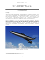
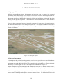
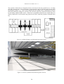
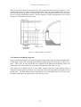
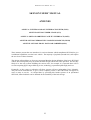
SKYLON
USERS’ MANUAL
Contact
One of the purposes of this document is to elicit feedback from potential
users as part of the validation of SKYLON’s requirements. Comments are
most welcome and should be sent to:
Reaction Engines Ltd
Building D5, Culham Science Centre, Abingdon,
Oxon, OX14 3DB, UK
Email: [email protected]
SKYLON Users’ Manual – Rev. 1.1
SKYLON USERS’
MANUAL
Compiled: Mark Hempsell and Roger Longstaff
Authorised: Alan Bond
Doc. Number - SKY-REL-MA-0001
Version – Revision 1.1
Date – Jan 2010
© Reaction Engines Limited - 2009
Reaction Engines Ltd
Building D5, Culham Science Centre, Abingdon, Oxon, OX14 3DB UK
Email: [email protected]
i
SKYLON Users’ Manual – Rev. 1.1
Frontispiece: SKYLON Take-off
ii
SKYLON Users’ Manual – Rev. 1.1
SKYLON USERS’ MANUAL
Contents
Acronyms and Abbreviations
vi
1. INTRODUCTION
1
1.1 Scope
1
1.2 Purpose
2
2. VEHICLE DESCRIPTION
3
2.1 SKYLON Configuration C2
3
2.2 SABRE
4
2.3 Typical Mission Profile
5
3. PAYLOAD INTERFACES
7
3.1 Payload Mass
3.1.1 Orbital performance
3.1.2 Suborbital Performance
7
3.2 Injection Accuracy
11
3.3 Envelope and Attachments
3.3.1 Payload Bay Envelope and Attachment
3.3.2 Attachment Interface
3.3.3 Payload Centre of mass Constraints
11
3.4 Environment
3.4.1 Load Environment
3.4.2 Acoustic Environment
3.4.3 Atmosphere Environment
3.4.4 Heating Flux
15
3.5 Payload Services
3.5.1 Disconnectable Electrical Connection
3.5.2 Data Bus Connection
3.5.3 Propellant
16
3.6 Mission Duration
iii
SKYLON Users’ Manual – Rev. 1.1
4. GROUND OPERATIONS
19
4.1 Spaceport Description
19
4.2 Payload Integration
19
4.3 Launch and Landing Sequence
21
ANNEX A: UNIVERSAL SPACE INTERFACE SYSTEM (USIS)
A1. INTRODUCTION
25
A2. USIS DESCRIPTION
25
A2.1 Operation Types
25
A2.2 USIS Interface Ring
26
A2.3 Active Clamps
27
A2.4 Pin Cone Docking Connection
27
A2.5 Hatch
28
ANNEX B: SKYLON UPPER STAGE (SUS)
B1. INTRODUCTION
29
B2. SUS DESCRIPTION
29
B2.1 SKYLON Upper Stage
29
B2.2 Mission Profile
29
B3. PAYLOAD INTERFACES
31
B3.1 Performance
B3.1.1 Expendable Mode
B3.1.2 Reusable Mode
31
B3.2 Payload Interfaces
B3.2.1 USIS Envelope and Attachment
B3.2.2 1666Adaptor Envelope and Attachment
32
B3.3 Electrical Interfaces
33
iv
SKYLON Users’ Manual – Rev. 1.1
ANNEX C: SKYLON ORBITING FACILITY INTERFACE (SOFI)
C1. INTRODUCTION
35
C2. SOFI DESCRIPTION
35
C3. PAYLOAD INTERFACES
36
ANNEX D: SKYLON PERSONNEL / LOGISTICS MODULE (SPLM)
D1. INTRODUCTION
37
D2. SYSTEM OUTLINE
37
D2.1 SPLM Description
37
D2.2 Mission Outline
38
D3. PAYLOAD PROVISIONS
38
D3.1 Mass Capability
38
D3.2 Under Floor CTB Provisions
39
D3.3 Cabin Bays
D3.3.1 Passenger Seats
D3.3.2 ISS Equipment Rack
D3.3.3 CTB Carrier
39
ANNEX E: SKYLON SMALL PAYLOAD CARRIER (SSPC)
E1. INTRODUCTION
41
E2. SSPC DESCRIPTION
41
E3. PAYLOAD INTERFACE
41
E3.1 Mechanical Interfaces
41
E3.2 Electrical Interfaces
42
E3.3 Mass Properties
42
v
SKYLON Users’ Manual – Rev. 1.1
Acronyms and Abbreviations
A
AFDX
ASAP
C
CTB
DC
FAA
g
GEO
GTO
hr
Hx
ISO
Isp
ISS
K
kg
km
kN
kPa
L/D
LEO
LH
LOX
m
MECO
mm
N
OMS
Pa
PAS 1666S
RMS
s
SABRE
SOFI
SOMA
SPLM
SSPC
SUS
TBD
USIS
V
W
Amperes
Avionics Full-DupleX switched ethernet
ARIANE Structure for Auxiliary Payloads
Degrees Celsius
Cargo Transfer Bag
Direct Current
Federal Aviation Administration
Surface acceleration due to Earth’s gravity
Geostationary Earth Orbit
Geostationary Transfer Orbit
Hour
Heat Exchanger
International Standards Organisation
Specific Impulse
International Space Station
Degrees Kelvin
Kilogrammes
Kilometres
Kilo-Newtons
Kilo-Pascals
Lift to Drag Ratio
Low Earth Orbit
Liquid Hydrogen
Liquid Oxygen
Metres
Main Engine Cut-Off
Millimetres
Newtons
Orbital Manoeuvring System
Pascals
Payload Adaptor System 1666S
Remote Manipulator System
Seconds
Synergistic Air-Breathing Rocket Engine
SKYLON Orbiting Facility Interface
SKYLON Orbital Manoeuvring Assembly
SKYLON Personnel / Logistics Module
SKYLON Small Payload Carrier
SKYLON Upper Stage
To Be Determined
Universal Spacecraft Interface System
Volts
Watts
vi
SKYLON Users’ Manual – Rev. 1.1
SKYLON USERS’ MANUAL
1. INTRODUCTION
1.1 Scope
This document outlines the performance and payload interfaces for the SKYLON launch system
(Figure 1) in its C2 configuration. This configuration differs from the C1 configuration which has
been reported in past published work†. C2 has been mostly created by a direct scaling of C1, with
the mass scaled by 1.25 and linear dimensions scaled by 1.08. It is intended as a starting point for a
major redesign exercise that will revise the SKYLON design to create configuration D1.
One area in which the C2 is not a direct scaling of C1 is the payload bay interfaces. These have
been revised in light of a series of market and future application studies and this User Manual
reflects the results of this redesign. Thus this document represents a starting point for user
requirements for the D1 design and does not necessarily represent the final user interfaces. It
follows that this document should not be used for the detailed design of hardware intended for
production.
Figure 1: SKYLON C2 in Flight
† e.g. Richard Varvill and Alan Bond, “The SKYLON Spaceplane”,
Journal of the British Interplanetary Society, Volume 57, pp. 22-32, 2004
1
SKYLON Users’ Manual – Rev. 1.1
1.2 Purpose
The purposes of this Users’ Manual are threefold. They are:
i) to provide a technical definition of the SKYLON spaceplane to its potential stakeholders;
ii) to provide a controlled definition of the user interfaces at a level comparable to other
launchers. This definition will be an aid for technical studies by those wishing to use
SKYLON as the assumed launch system;
iii) to elicit feedback from potential users on the performance and interfaces as currently
envisaged. This will act as the key validation of the user requirements before finally
committing to the system development stage.
The SKYLON launch system has the requirement to be able to place payloads into Low Earth Orbit
(LEO). However, many payloads require higher energy orbits, or need to be delivered to orbiting
facilities or are too small to match the payload mounting provisions. To meet the additional
requirements SKYLON will have a range of complimentary systems to extend its capability. These
include:
- An upper stage capable of reaching other Earth orbits and escape trajectories
(called SKYLON Upper Stage – SUS);
- An adaptor to enable docking and berthing with orbiting facilities
(called SKYLON Orbiting Facilities Interface – SOFI);
- A pressurised module that can carry crew and logistics
(called SKYLON Personnel / Logistics Module – SPLM);
- A carrier structure capable of carrying smaller payloads
(called the SKYLON Small Payload Carrier - SSPC).
The user interfaces for these complimentary systems are given in Annexes A-E. The systems
outlined here are those expected to be available with SKYLON on entry into service. It would not
preclude the development of other competing systems performing similar functions.
2
SKYLON Users’ Manual – Rev. 1.1
2. SKYLON C2 VEHICLE DESCRIPTION
2.1 SKYLON Configuration C2
The SKYLON launch vehicle is a winged single-stage-to-orbit space plane, powered by the SABRE
engine which can operate in either an air-breathing or a pure rocket mode. The vehicle takes off
from an extended runway with the engines in air-breathing mode. It accelerates to Mach 5.14 and
28.5 km altitude before switching over to the pure rocket mode and climbing to a Low Earth Orbit.
Once the payload is deployed and operations in orbit are completed, the vehicle returns to earth, reenters the atmosphere and glides back to a runway landing.
SKYLON (Figure 2) consists of a slender fuselage which contains propellant tankage and a payload
bay. Its delta wings attached midway along the fuselage carry the SABRE engines in axisymmetric
nacelles on the wingtips. Figure 2 also defines the direction of the vehicle axes. Key features of the
SKYLON C2 are given in Table 1, assuming a 15 tonne payload into a 300km circular equatorial
orbit from an equatorial launch site.
Figure 2: SKYLON Cutaway View and Axes Definition
Length
Fuselage diameter.
Wingspan
Unladen mass
Propellant mass
Nominal take-off mass
83.3 m
6.75 m
25. 4 m
53 tonnes
277 tonnes
345 tonnes
Maximum air-breathing thrust
Isp in air-breathing mode
Maximum thrust in rocket mode
Isp in rocket mode
Thrust range (rocket mode)
Operational life
2 x 1350 kN
35000 N s / kg
2 x 1800 kN
4500 N s / kg
55% - 100%
200 flights
Table 1: SKYLON Configuration C2 Features
SKYLON’s main structure consists of a space frame constructed from carbon fibre reinforced
plastic struts. The non-structural aluminium propellant tanks are suspended within the framework
by Kevlar ties. The frame is covered with sheets of a reinforced glass ceramic material which acts
as the aeroshell and main thermal protection backed by a multilayer metallic heat shield.
3
SKYLON Users’ Manual – Rev. 1.1
In addition to the main propulsion system tanks there are a set of secondary cryogenic tanks which
feed the orbital manoeuvring engines, the reaction control thrusters and the fuel cell power supply.
2.2 SABRE Engine
SKYLON is powered by a combined cycle rocket engine which has two operational modes. In one
mode air captured from the atmosphere is used as the oxidiser and in the other liquid oxygen from
the internal tanks is used as the oxidiser.
The SABRE engine (Figure 3) uses sub-cooled liquid hydrogen as its fuel and sub-cooled liquid
oxygen as the oxidiser in rocket mode. In rocket mode the engine operates as a closed cycle high
performance rocket engine. In air-breathing mode the liquid oxygen flow is replaced by atmospheric
air. The airflow is drawn into the engine via an axisymmetric intake and is cooled to cryogenic
temperatures by a pre-cooler heat exchanger. The pre-cooler heat exchanger is part of a closed
cycle helium loop using the hydrogen fuel as the heat sink before it enters the combustion chamber.
After cooling the air is compressed and fed to the combustion chamber. Throughout most of the
flight regime the intake captures more air than required. The excess air is passed down a spill duct
which incorporates a burner to recover some of the drag losses.
Figure 3: The SABRE Engine
4
SKYLON Users’ Manual – Rev. 1.1
2.3 Typical Mission Profile
SKYLON mission activity will start with the loading of the payload in an integration facility. It
will then be towed out to a fuelling apron to be loaded with liquid hydrogen, liquid oxygen and
helium. Once loaded and powered up SKYLON is towed to the head of the take-off runway.
With the vehicle stationary the engines are ignited in air-breathing mode, burning hydrogen fuel
with pre-cooled compressed air. When nominal performance has been verified the brakes are
released and the vehicle begins its take-off roll. The vehicle takes off from the runway in the same
manner as a high performance jet aircraft with a take-off speed close to Mach 0.5. Following takeoff the vehicle jettisons around 3 tonnes of water, which would have been required by the boiling
water braking system for a rejected take-off, should a malfunction have occurred.
After take-off the vehicle climbs and accelerates on its predetermined trajectory for 694 seconds
(approx 11½ minutes), by which time it has reached an altitude of 28.5 km and a speed of Mach
5.14. The vehicle is now 620 km downrange from the launch site.
SKYLON now switches to pure rocket propulsion, burning liquid hydrogen and liquid oxygen in
the common combustion chambers. The vehicle now climbs rapidly and performs a gravity turn in
order to inject into an 80 by 300 km transfer orbit after a further 285 seconds (4¾ minutes), at
which time main engine cut-off occurs. Figure 4 shows a nominal ascent profile.
Figure 4: Ascent Trajectory
SKYLON then jettisons main tank residual propellant and continues on a ballistic trajectory for a
further 44 minutes until it reaches apogee at 300 km altitude, at which time it fires its orbital
manoeuvring system (OMS) engines in order to circularise the orbit. After routine system
checkouts the vehicle opens its payload bay doors and deploys its payload. The payload then
proceeds with its mission independently.
5
SKYLON Users’ Manual – Rev. 1.1
Figure 5: Descent Trajectory
The SKYLON vehicle now returns to its base. After the payload bay doors have been closed the
OMS engines make a retrograde burn in order to achieve a suitable velocity vector for re-entry.
This manoeuvre is timed to return the vehicle to its launch site (or any other nominated landing site)
via a pre-calculated trajectory. The vehicle descent trajectory is unpowered with energy
management achieved through S turns as a glider (in the same manner as the Space Shuttle, but with
much increased manoeuvrability due to a higher L/D ratio) and the vehicle lands automatically. A
typical descent trajectory is shown in Figure 5.
Landing speed is around 130 knots (65 m/sec) with crosswinds of up to 30 knots.
The SKYLON vehicle is then serviced and prepared for its next mission.
6
SKYLON Users’ Manual – Rev. 1.1
3. PAYLOAD PROVISIONS
3.1 Mass
3.1.1 Orbital Deployment
Figures 6 to 10 below give SKYLON’s performance for orbital deployment from various launch site
latitudes. The graphs show the payload mass delivered into circular orbit plotted against orbital
altitude. Each graph has a series of curves for various orbital inclinations. The value for 52° is
given as this is the inclination of the ISS, and an inclination of 98° is given as an approximation to a
Sun Synchronous orbit. Where the orbit inclination is below the launch site latitude the results are
not given in general as these orbits are not practical.
The current established maximum orbital altitude is 800 km as the ability for SKYLON to return
above that altitude has not been fully evaluated. If altitudes greater than 800 km are of interest
please contact Reaction Engines Limited to establish their feasibility.
Figure 6: Delivered Mass for Equatorial Launch Site
7
SKYLON Users’ Manual – Rev. 1.1
Figure 7: Delivered Mass for 15 degree Launch Site
Figure 8: Delivered Mass for 30 degree Launch Site
8
SKYLON Users’ Manual – Rev. 1.1
Figure 9: Delivered Mass for 45 degree Launch Site
Figure 10: Delivered Mass for 60 degree Launch Site
9
SKYLON Users’ Manual – Rev. 1.1
3.1.2 Suborbital Deployment
SKYLON has the capability of maximising the payload mass by performing a suborbital
deployment and using a payload supplied propulsion system to perform the final orbit insertion
manoeuvres.
In this mission profile the vehicle flies an ascent trajectory which places it into an orbit that will
allow a minimum of 5 minutes above an altitude of 135 km and achieve a flight path angle no
steeper than minus 3 degrees at the re-entry interface of 120 km. The nominal transfer orbit to
satisfy these constraints has been determined as follows:
Apogee: 157 km (radius of apogee = 6532 km)
Perigee: minus 2000 km (radius of perigee = 4375 km)
Velocity at apogee: 6966 m/s
Deployment is started 30 minutes after MECO. When the vehicle is above 135 km (a minimum
deployment altitude determined by aerothermal constraints) the payload bay doors are opened and
the payload is deployed. SKYLON then proceeds to separate from the payload, which is now
independent, and closes the payload bay doors. After 2 – 3 minutes the payload fires its engine in
order to raise it to its operational orbit. SKYLON then re-enters as with an orbital mission, and
lands at a site about 10,000 km downrange from its launch site. The vehicle may then be “towed”
back to its base. The suborbital deployment sequence with design values for sequencing is given in
Figure 11.
Figure 11: Suborbital Deployment Sequence and Timing
The total payload mass that may be deployed during this mission is 30 tonnes which is determined
by the structural strength of the payload interfaces. However, the payload must use some of this
mass to provide its own propulsion system (or a dedicated propulsion stage) in order to raise itself
to its operational orbit. Typical velocity increments which will be necessary are:
To 300 km circular orbit: ∆ V1 = 858 m/s; ∆ V2 = 42 m/s (2 burn Hohmann transfer)
To GTO: ∆ V = 3286 m/s
To escape velocity: 4056 m/s (local escape velocity = 11,051 m/s)
10
SKYLON Users’ Manual – Rev. 1.1
Individual users may calculate their propulsion requirements on a case by case basis using the above
data.
3.2 Injection Accuracy
The precise payload injection accuracy for SKYLON has not yet been established but it will be
high. The targets for an orbital deployment are to have an orbital inclination accuracy of 0.01
degrees prior to deployment and to have the payload achieve a positional accuracy of 10 m and a
velocity accuracy of 0.01 m/s after deployment.
3.3 Envelope and Attachments
The SKYLON payload bay (Figure 12) is sized to scope most existing launch system payload
envelopes and be appropriate to the 15 tonne mass capability. It is located at the centre of the
vehicle over the wing structure and has a U shaped cross section with two opening doors above it,
which, once in orbit, expose the payload to space.
Figure 12:The SKYLON Payload Bay
The bay has two payload interfaces, one in the front and the other at the rear. The front location has
provisions to load cryogenic oxygen, hydrogen and helium, but in all other respects the two
interfaces are identical and mirror each other. A payload can, therefore, be placed at either end
without alteration. Payloads will use the provision which locates the centre of mass to be within the
constraints defined in Section 3.3.3; this will in most cases be the front mounting. It is possible to
use both attachments simultaneously to mount two payloads in the bay at one time, providing that
when combined, the mass and mass properties constraints are met.
11
SKYLON Users’ Manual – Rev. 1.1
3.3.1 Payload Bay Envelope
The volume available to the payload and the location of the payload attachments in the SKYLON
payload bay are shown in Figure 13. This is a static volume and assumes a 20 mm allowance for
payload dynamic movement outside this envelope.
Figure 13: Payload Envelope and Attachment Geometry
12
SKYLON Users’ Manual – Rev. 1.1
3.3.2 Attachment Interface
The payload is mechanically attached to SKYLON by three trunnions in a plane: one keel trunnion
taking loads along the X and Y axes and two sill trunnions taking loads along the X and Z axes.
The position and dimensions of the trunnion hold-down are shown in Figure 14. The trunnions
fitted to the payloads which correspond to these hold-downs are defined by Figure 15.
Figure 14: Payload Attachment Location and Dimensions
Figure 15: Payload Trunnions
The sill attachment can be opened during the flight to release the sill trunnions and allow the
payload to be extracted along the Z axis.
The payload sill attachment also incorporates a deployment mechanism to eject the payload during
flight without the need for any additional equipment. The sill attachment opens to release the
trunnions and two synchronised actuators push on the sill trunnions with a travel of 200 mm along
13
SKYLON Users’ Manual – Rev. 1.1
the guides shown in Figure 13. These guides are supplemented by the keel trunnion which also
reacts the cantilever loads. The mechanism accelerates at 0.66 m/s2 to give a release velocity of 0.5
m/s.
3.3.3 Payload Centre of Mass Constraints
In addition to the overall mass constraint determined by SKYLON’s overall performance (defined
in sections 3.1.1. for orbital mission and 3.1.2 for suborbital missions) there are constraints on the
payload mass due to centre of mass constraints imposed by the limitations of SKYLON’s pitch
control system during re-entry. The centre of mass versus overall mass constraints which are
applicable to the X axis are shown in Figure 16. Note the payload bay fittings are sized for a
maximum payload mass of 30 tonnes.
Figure 16: Maximum Payload Mass versus Payload Centre of Mass along X axis
In the Y and Z axes the payload centre of mass must not produce a moment greater than +/- 60,000
N m about the payload bay reference axis.
14
SKYLON Users’ Manual – Rev. 1.1
3.4 Environment
3.4.1 Load Environment
The quasi-static design limit loads applicable to the payload are given in Table 2.
CASE
Ascent
Re-entry
X axis
- 3g / + 0.5 g
+/- 0.5 g
Y axis
+/- 0.5 g
+/- 0.5 g
Z axis
+ 2 g / - 0g
+ 2 g / - 0g
Table 2: Quasi-Static Design Loads
Loading on payloads mounted to the complimentary systems such as the SKYLON Upper Stage
(Annex B) or the SKYLON Small Payload Carrier (Annex E) have not yet been determined but are
unlikely to greatly exceed those in Table 2.
3.4.2 Acoustic Environment
The acoustic environment in the payload bay has not yet been determined but is expected to be
below 100 dB at all frequencies (where 0 dB corresponds to 2 x 10⁻⁵ Pa RMS).
3.4.3 Atmosphere Environment
Once the payload bays doors are closed in the integration hall the payload bay is purged to a pure
dry nitrogen atmosphere with a pressure of 102 kPa +/- 0.5 kPa and a temperature between +10° C
+ 40° C.
During ascent the nitrogen in the payload bay is vented to the ambient static pressure. During reentry descent dried air is introduced into the payload bay again to match the ambient static pressure.
Figure 17 shows the pressure history during ascent and re-entry to and from 80 km altitude.
Figure 17: Payload Bay Ambient Pressure during Ascent and Descent
15
SKYLON Users’ Manual – Rev. 1.1
The design maximum rate of depressurisation during ascent is 700 Pa/sec for 30 seconds and during
descent it is 300 Pa/sec.
3.4.4 Heating Flux
While in the payload bay the payload bay wall temperature is between 0°C and 20°C; assuming that
the payload is not powered and acting as a further heat source.
If suborbital deployment as outlined in section 3.2 is employed then at the point of deployment the
aerothermal heating load is below 1150 W/m2. Other heating factors such as solar and Earth
radiation fluxes are not included in this value.
Orbital deployment induces no appreciable aerothermal heating load.
3.5 Payload Services
3.5.1 Disconnectable Electrical Connection
Each SKYLON payload attachment point interface has a Disconnectable Electrical Connection
which can provide electrical power and some status signals to the payload. This connection is an
integral part of the keel trunnion and the pin functions are defined in Figure 18.
The payload electrical power connection provides a maximum 15 A at 28 V DC nominal to MILSTD-704F (for reference, this corresponds to a nominal power of 420 watts). The total energy
available to the payload throughout the mission, starting when payload power supply is connected
during integration, is 500 A hr.
If two payloads are sharing the bay the maximum current that can be drawn simultaneously is 20 A
(for reference, this corresponds to a nominal power of 560 watts). The constraint on the total
energy available to the payload over the mission remains as for a single payload.
The connector also provides the payload with a 5 line parallel command / status alert bus. Each
signal has an output voltage of 28 V ± 4 V of 2 seconds duration. This provides a 4 bit signal with
even parity checking. Four of the commands are reserved; these are:
1000-1 Abort Alert - the SKYLON has initiated an abort manoeuvre
0100-1 Door Opening Alert – the payload bay door will open in 30 seconds
0010-1 Door Closing Alert – the payload bay door will close in 30 seconds
0001-1 Deployment Alert – the payload will be deployed in 30 seconds
The actions of other commands are defined by the payload.
The payload is required to provide a resistive load greater than 100 ohms which is immune to single
point failure. The payload is also required to fully protect the circuit against any overload or
voltage overshoot induced by its circuits.
16
SKYLON Users’ Manual – Rev. 1.1
Figure 18: Keel Trunnion Pin Connections
3.5.2 Data Bus Connection
There is provision for the payload to connect to the SKYLON data bus at both the front and rear
interface positions. The precise connection type and its location are not yet established, but it will
be located in the area defined in Figure 19.
Figure 19: Payload Connector
Location
The form of the main SKYLON data bus has not yet been established. It will be a flexible
architecture high data rate standard which can be certified to meet aerospace safety requirements. It
could be an existing aircraft standard such as AFDX, or it could be an enhanced version of a space
standard such as Spacewire.
Given the complex interactions this interface generates, it is only available in special circumstances
and the compatibility analysis would incur significant extra costs over the basic launch cost for the
payload use. It is envisaged that basic infrastructure elements, such as the SUS, SOFI and SPLM,
which extend SKYLON’s capability would be used many times.
17
SKYLON Users’ Manual – Rev. 1.1
3.5.3 Propellant Supply
The front payload attachment interface has the provision for the payload to connect into SKYLON’s
propellant fill, drain and venting system. These provisions are defined in Table 3.
Propellant
Liquid Hydrogen
Liquid Oxygen
Helium
Connections
1 Fill/drain
1 Fill/drain
2 Fill/drain
Temp.
16 K
80 K
4.2 K
Press.
2 bar
2 bar
1 bar
Rate
TBD
TBD
TBD
Table 3: Propellant Delivery Connections
The exact nature of these connections has not yet been determined but their location is in the area
defined in Figure 19.
These capabilities are expected to be used with upper stages using cryogenic propellants, such as the
SUS, or systems like the SPLM, which use fuel cells to generate electrical power. Given the
complex interactions this interface generates, it is only available in special circumstances and would
incur significant extra costs over the basic launch cost for the compatibility analysis.
3.6 Mission Duration
SKYLON can remain on orbit for up to 4 days. This must include any contingency time to handle
any problems that might develop during the mission, so it is anticipated in most instances the
nominal mission time would be no more than 2 days.
18
SKYLON Users’ Manual – Rev. 1.1
4. GROUND OPERATIONS
4.1 Spaceport Description
SKYLON operates like an aircraft. Its integration and servicing occur in a hanger, it is supported
horizontally on its undercarriage and for flight it is towed out to a runway for fuelling and take-off.
The location and detailed design of the launch site or sites have not yet been established; therefore
this section describes an idealised flow for launch facilities and operations which would alter from
port to port and operator to operator. It follows that the interfaces defined here are more indicative
and illustrative than definitive.
Figure 20 shows a conceptual spaceport layout. It centres on a 5.5 km runway for exclusive use by
the SKYLON vehicle and a 3.2 km runway for aviation use. The operators of SKYLON fleets have
separate hangers and payload support facilities. There is a general SKYLON maintenance building
used by all operators.
Figure 20: Spaceport Layout.
4.2 Payload Integration
It is anticipated that payload launch preparation would occur in special areas as part of the hanger
and that overhead cranes would carry the payload from its mechanical support equipment rig in the
preparation area to the SKYLON vehicle to be lowered into the payload bay. A concept design for
this facility is given in Figure 21 and an artist impression of the interior in Figure 22.
The air quality in the payload integration and loading areas is to ISO 9 as defined in ISO 14644-1,
“Clean rooms and associated controlled environments--Part 1: Classification of air cleanliness”.
While most payload preparation operations would be conducted in this facility, any propellant
loading required by the payload would be done in a separate fill area. The fuelled spacecraft would
then be returned and ready for integration
19
SKYLON Users’ Manual – Rev. 1.1
The payload is lifted from its integration fixtures and lowered into the payload bay by a loading
rack and overhead crane. The crane attaches to the payload by the rear 50 mm square section of the
sill trunnions (Figure 15). Once in the payload bay the loading rack is disconnected and the
SKYLON hold-downs clamps are activated. The electrical connectors in the keel trunnion are made
by the loading without further action. If data bus or propellant connections are required they are
made by hand and are accessed from the ground access doors, while the payload is mounted in the
bay.
Figure 21: SKYLON Hanger and Payload Integration Facility
Figure 22: Interior of SKYLON Payload Integration Facility
20
SKYLON Users’ Manual – Rev. 1.1
There are two access doors to the payload bay. The location and size are shown in Figure 23. One
is at the front of the bay on the port side and the other at the rear on the starboard side. They are
positioned in this way in order to enable the same access to the payload whether it is located in the
front or rear payload mounting interface. The door opening is sized to correspond to a FAA Type B
emergency exit [FAR Part 25 Section 807].
Figure 23: Payload Bay Access Doors
4.3 Launch and Landing Sequence
Figure 24 details the sequence of events from payload integration to take-off, which nominally takes
a little under 4 hours and, if needed, from landing to payload removal, which takes a little over 2
hours. These times do not include the time required for the SKYLON turnaround, which will
depend upon how it is operated, but is expected to be typically in the order of a day.
After SKYLON is fuelled there is a 240 minute window before the flight attempt must be
abandoned and the vehicle de-fuelled. This is the time taken for the propellant in the tanks to reach
boiling point. This hold capability allows enough time for a second opportunity to fly to any given
orbit plane should the first opportunity be missed for any reason.
21
SKYLON Users’ Manual – Rev. 1.1
Figure 24: Launch and Landing Sequence and Timeline
22
SKYLON Users’ Manual – Rev. 1.1
SKYLON USERS’ MANUAL
ANNEXES
ANNEX A: UNIVERSAL SPACE INTERFACE SYSTEM (USIS)
ANNEX B: SKYLON UPPER STAGE (SUS)
ANNEX C: SKYLON ORBITING FACILITY INTERFACE (SOFI)
ANNEX D: SKYLON PERSONNEL /LOGISTICS MODULE (SPLM)
ANNEX E: SKYLON SMALL PAYLOAD CARRIER (SSPC)
These annexes present the user interfaces for various elements which compliment SKYLON to give
it additional capabilities over the basic vehicle. The majority of payloads (around 80%) will require
the use of one of these elements.
The designs reflected here are far more conceptual than the design definition of the basic SKYLON
vehicle, and consequently may not reflect the final designs which will enter operation. Nor are they
likely to be the only systems fulfilling the various roles; for example it is expected there will be
several competing upper stages differing in size, technology, operational philosophy and cost.
Eventually, as they come to realisation, all these systems will have independent Users’ Manuals.
They have been included here to give a more complete picture of how SKYLON will appear to
users on entry to service. It is hoped that, by providing this broader picture of an operational
SKYLON, better feedback can be obtained on the suitability of the basic design.
23
SKYLON Users’ Manual – Rev. 1.1
24
SKYLON Users’ Manual – Rev. 1.1
ANNEX A: UNIVERSAL SPACE INTERFACE SYSTEM (USIS)
A1 INTRODUCTION
This annex defines the docking berthing interface used by the complimentary infrastructure
elements to SKYLON. This acts as a universal physical interface between all medium and large
space systems whether manned or unmanned.
This docking standard will become the standard in-orbit connection system even if it is not planned
as such. None of the existing three docking and berthing systems used on the International Space
Station look like becoming international standards. As things stand Russia seems to plan on
continuing the use of the Soyuz pin / cone system, while the USA and Europe seem agreed on a new
system variously known as Low Impact Docking System, Advanced Docking System and
International Docking / Berthing Standard. This may be an emerging international standard (with
reference to USA and Europe at the moment) for a docking port, but, while the detailed interfaces of
this new system have not been published, what is known of it suggests that it has serious limitations
which consequently makes it unsuitable as a long term standard. Of the many deficiencies in
functionality the most important are the hatch size, which at 800 mm is too small for many of the
items such as equipment racks which need to pass through, and the lack of extendibility to
integrated connections. Therefore a new interface has been designed for SKYLON applications
called the Universal Space Interface System (USIS). It is shown in its fullest form in Figure A1.
Figure A1: The Universal Space
Interface System (USIS)
The USIS design outlined in this annex is conceptual in order to illustrate the
requirements of SKYLON’s complimentary systems. In practice, whatever ends
international standard will have to be used; this is at least the case for the SPLM.
compromises over the functionality incorporated in the USIS will impact on
complimentary systems can do.
connection
up as the
However,
what the
A2 USIS DESCRIPTION
A2.1 Operation Types
USIS has four types of connection function which are defined in Table A1. These have upward
compatibility where, for example, an integrated level interface can be integrated to a docking or
berthing level interface, or a docking system can be berthed to a berthing level interface. This
25
SKYLON Users’ Manual – Rev. 1.1
backward compatibility has proved an important factor in maintaining the operational flexibility of
the various support systems which use the USIS.
Level I Integrated
Level II Berthing
Level IIIHard Docking
Level IVSoft Docking
Description
Ground made connection either
permanent or breakable
In orbit connection with a
manipulator
In orbit connection between two
free flying spacecraft
As hard docking with active
control to reduce impact loads
Contact Velocity
Negligible
Misalignment
1 mm
Nominally zero
Below .01 m/s
0.5 m/s
30 mm
Nominally zero
Below .01 m/sec
+/- 150 mm and
10 degrees in all axis
+/- 150 mm and
10 degrees in all axis
Table A1: USIS Functional Levels
The USIS has both pressurised and unpressurised variants. Only one side of USIS needs to be
active for berthing or docking operations as the USIS can be implemented as a passive only
connection.
When the four function levels are combined with pressurisation options and the passive/active
option there is a 16 element functional matrix of operational options, as shown in Figure A2. Figure
A2 also shows that the 16 options can be accommodated by 8 implementations of the USIS
standard.
Figure A2: USIS Functional
Variants
The mass of the USIS will clearly depend on what version is incorporated and how it is integrated
into the final systems. It thought to range from 130 kg (including mounting cone or cylinder) for an
unpressurised passive ring only version to 360 kg for an active pressurised soft dock system.
A2.2 USIS Interface Ring
The most basic version consists of the interface ring and the bolt holes and would be used for
permanent ground integration of two systems, such as, the space station modules which will be
launched mated together. This ring is the foundation of the USIS. It has an outer diameter of 1620
mm and a minimum inner diameter of 1480 mm. It has the following functions;
26
SKYLON Users’ Manual – Rev. 1.1
•
•
•
•
•
•
•
the main bearing surface,
a redundant pair of sealing O rings,
8 Bolts for a permanent connection or with explosive bolts if separation is required,
4 spring locations and corresponding pusher plates,
4 Berth guides that take out 30 mm of misalignment,
4 Capture clamps used with clamps mechanisms for multiple attachments,
1 set of electrical power and data connections.
The locations of these functions are shown in Figure A3.
Figure A3: The Location of USIS Ring Functions
A2.3 Active Clamps
All variants of the USIS which require in orbit active connections (i.e. not using the bolt option)
make the final connection with four equi-spaced clamp mechanisms. Four clamps are sufficient, but
if both sides are active USIS variants both sets can be activated. If the full corridor defined in
section A2.5 is required both sets of clamps need to be closed as they intrude into the areas when
open.
In berthing operations these clamps act as the capture latches. In docking operations they are
activated to make the final structural connection after capture has been achieved by the pin cone
connection.
A2.4 Pin Cone Docking Connection
A pin and cone mechanism is fitted when a docking function is required involving additional
alignment and capture mechanism. The pin or drogue is guided to the centre of the cone where
capture latches in the pin’s tip engage and make the initial connection. These have been used on
past docking systems, for example, Apollo and Soyuz. However, in these cases, the two ports to be
mated were different; one was with the pin or drogue and the other with the guide cone. To make
the USIS port androgynous the port has both a pin and a cone offset from the centre. Only the pin
27
SKYLON Users’ Manual – Rev. 1.1
on the active side needs to activate its capture latches whilst the other passive pin in the active side’s
cone takes out rotational misalignments.
The USIS pin has a conical guidance skirt beneath the capture latches to take out rotational
misalignments about X and Y axes.
Both the cone and pin extend beyond the interface plane. The cone protrudes by 110 mm and the
pin by 198 mm.
To make the USIS a soft dock system the active pin is mounted to a Stewart platform which can
control the pin with a sufficient 6 degrees of freedom movement. This is to enable it to be guided
with minimal force into the cone’s receptor before engaging the capture latch.
A2.5 Hatch
The key reason for adopting the twin offset pin/cone docking arrangement is to enable the hatch in
the pressurised variants of the USIS to fully utilise the 1480 mm internal diameter of the interface
ring. The resulting hatchway dimensions are defined in Figure A4.
Figure A4: USIS Hatch Opening Dimensions
28
SKYLON Users’ Manual – Rev. 1.1
ANNEX B: SKYLON UPPER STAGE (SUS)
B1 INTRODUCTION
SKYLON has only the capability to place payloads into Low Earth Orbit. To reach higher orbits
and Earth escape orbits requires an upper stage.
It is anticipated many commercial upper stages would be developed for SKYLON filling specialist
market needs and trying to exploit some technical or commercial innovation. However there will be
one stage that is developed as part of the SKYLON system to provide a full launch capability on
entry into service. This is called the SKYLON Upper Stage (SUS)
The SUS stage is optimised to provide the maximum payload into geostationary transfer orbit from
a once round suborbital deployment. However it can also deliver effective payloads to all high
earth and planetary escape orbits using both sub-orbital and orbital deployment and it can also lift
payloads into Low Earth Orbit that are substantially heavier than SKYLON alone can achieve using
down range suborbital deployment. In some cases the SUS stage can be recovered for reusability.
This annex describes and defines the user interfaces for the SUS.
B2 SUS DESCRIPTION
B2.1 SKYLON Upper Stage
As shown in figure B1 the SUS has a compact design to minimise the payload bay occupied by the
stage and hence maximise the volume available to the payload. A disk shaped 4.7 m diameter panel
is the main structure. The attachment trunnions are directly connected to this panel, as is the liquid
oxygen tank. The toroidal hydrogen tank and engine assembly are connected to a cantilevered truss
structure. The payload mounting interface connects to the other side of the panel by a conical
structure.
The payload interface can be either the USIS described in Annex A, or a conventional marmon
clamp interface such as the Ariane 5 PAS 1666S.
The engine is the SKYLON Orbital Manoeuvring Assembly (SOMA) used by SKYLON as primary
propulsion after MECO. It uses liquid oxygen and liquid hydrogen propellants and has inherent
usability derived from its role on SKYLON. This assembly consists of 2 engines each with 2 thrust
chambers, and provides a total thrust of 50 kN
B2.2 Mission Profile
The SUS is loaded into the SKYLON payload bay with its payload already integrated but without
propellants. Once SKYLON is on the fuelling apron the liquid oxygen and liquid hydrogen
propellants for the SUS are loaded as part of the overall loading process through the connections
defined in section 3.5.3.
The stage can be used in both an expendable and reusable mode. In a nominal expendable mission
SUS deployment takes place from a very low Earth orbit with an altitude of 190 km. Deployment
would take place on the first orbit with a minimum of 10 minutes between deployment and SUS
main engine burn.
29
SKYLON Users’ Manual – Rev. 1.1
Figure B1: SKYLON Upper Stage
Only one reusable mission has been looked at in detail and this is to Geostationary Transfer Orbit
(GTO) from a near equatorial launch site. The SUS, its payload (in the front payload position) and
a recovery system (mounted in the rear position) are launched into a 300 km altitude circular orbit
which has a 7:1 resonance with the GTO. After deployment the SUS places the payload into GTO
with a perigee burn. After one complete orbit it performs another circularisation burn to place it
back into a 300 km LEO which is close enough for the SKYLON that launched it to dock, safe the
stage and return to the forward payload location for return to Earth. Because of the need to dock the
SUS for recovery reusable missions will require the use of the USIS interface.
The use of the SUS as the make up propulsion with suborbital deployment manoeuvre as described
in section 3.1.2 is also possible. This mode will increase the both the total and specific LEO launch
costs as the cost of the SUS and the cost recovery from the downrange landing site must be
included. This mode is expected to be used when the payload is larger than the SKYLON’s orbital
capability and it is not practical to divide the payload up and assemble it in orbit.
30
SKYLON Users’ Manual – Rev. 1.1
B3 PAYLOAD INTERFACES
B3.1 Performance
Figure B2 gives the ∆V the SUS can provide against payload mass as determined by the rocket
equation given
- the SOMA engines have a specific impulse of 4562 N s /kg,
- the stage has maximum usable fuel load of 7000 kg,
- the end of burn mass of 950 kg.
The different payload interface options do not alter the mass to within the errors and margins of the
mass budget at its current status.
Figure B2: SUS Performance
B3.1.1 Expendable Mode
The nominal orbit for deployment of the SUS on an expendable mode mission is a 190 km circular
orbit with an orbital velocity of 7790 m / s. In this orbit the maximum deployed mass of SUS with
its payload is 16 tonnes
For a Geostationary transfer orbit mission the maximum payload is achieved with a propellant load
of 6.68 tonnes and this delivers a payload of over 8.25 tonnes.
With this mission the SUS places this payload into an orbit with the following characteristics:
Apogee altitude – 35787 km
Perigee altitude – 190 km
Inclination – as launch site
31
SKYLON Users’ Manual – Rev. 1.1
B3.1.2 Reusable Mode
For the reference reusable mission to geostationary transfer orbit the SUS carries a fuel load of 6.75
tonnes and this corresponds to a payload of 6.25 tonnes.
With this mission the SUS places this payload into an orbit with the following characteristics:
Apogee altitude – 35787 km
Perigee altitude – 300 km
Inclination – as launch site
B3.2 Payload Interfaces
B3.2.1 USIS Envelope and Attachment
The baseline payload interface for the SUS is the USIS. This can be the simple integrated variant
but if the stage is to be reused then the Passive Unpressurised Docking variant is required and the
pin / cone protrusions above the interface plane need to be accounted for.
The envelope available to the payload envelope for the SUS is defined in Figure B3. The cross
section is as the normal SKYLON deployment envelope defined in Figure 13.
Figure B3: SUS with USIS Interface Payload Envelope
B3.2.2 1666 Adaptor Envelope and Attachment
For an expendable mission the SUS payload interface can be made compatible with the Ariane 5
PAS 1666S adaptor as defined in the Ariane 5 User Manual (Issue 5, Revision 0 July 2008). The
connection is an aluminium ring with the payload held in place with a clamp band. Separation is
via a “soft” opening of the clamp band and 12 separation springs equi-spaced outside the ring.
The payload envelope and key features of the mounting interface are defined in Figure B4. The
cross section is as the normal SKYLON deployment envelope defined in Figure 13. As currently
32
SKYLON Users’ Manual – Rev. 1.1
envisaged the overall payload interfaces would be identical or less constraining than on Ariane 5
with the exception of the facilities for nitrogen purge on SKYLON.
Figure B4. SUS 1666S Compatible Attachment Interface
This interface is capable of carrying a maximum mass of 9 tonnes and a moment of 22,500 kg m.
Other adaptor standards could also be accommodated. Like the 1666 Adaptor these would attach to
the SUS via a specialist cone structure connecting back to the main panel using 64 M8 bolts equispaced on a 3240 mm diameter circle.
B3.3 Electrical Interfaces
A power supply of 28V and 0.5A maximum current is available to the payload.
The commands and telemetry available to the payload are TBD but will be consistent with the datalink provisions of the USIS.
33
SKYLON Users’ Manual – Rev. 1.1
34
SKYLON Users’ Manual – Rev. 1.1
ANNEX C: SKYLON ORBITING FACILITY INTERFACE (SOFI)
C1 INTRODUCTION
While SKYLON can perform the orbital manoeuvres to rendezvous with orbiting facilities it does
not have the provisions required to physically connect, either by docking or berthing, as part of the
main airframe. If this function is required it must either be integrated into the payload or a
SKYLON Orbiting Facility Interface (SOFI) must be flown with the payload.
This annex describes and defines the user interfaces for the SOFI.
The SOFI provides means by which SKYLON with a main unpressurised payload can dock (or
berth - as it has provision for both types of operation) with orbiting facilities such as space stations
while leaving most of the payload bay available for the main payload which once the SOFI has
connected the SKYLON and the facility can be removed.
C2 SOFI DESCRIPTION
SOFI (Figure C1) mounts in the rear payload location and has a standard USIS docking port to
connect to the orbiting facility. The port is held in the rear payload bay protrusion by five struts
which connect back to a U shaped frame which stretches across the payload bay. This frame is also
the structure to which the other equipment and the hold-down trunnions are mounted.
Figure C1: SKYLON Orbiting Facility Interface (SOFI).
In addition to the docking/berthing port the SOFI carries the radar and optical alignment system
needed for final approach and alignment to the orbital facility. It also has a standard grapple point
to enable SKYLON and its payload to be captured in free flight and then berthed as opposed to
docked if the orbiting facility has a Remote Manipulator System. The design philosophy is that the
main payload needs no provisions to reach the facility, except a grapple point if it is required to be
removed from the bay.
Although primarily designed to deliver unpressurised payloads the port is a capable of being
pressurised. The concept design has added a small pressurised container to the docking port which
can carry a double Cargo Transfer Bag up to 50 kg in mass. The flight can therefore be used to
deliver a small amount of urgent or otherwise opportune logistics in addition to the main payload.
35
SKYLON Users’ Manual – Rev. 1.1
C3 PAYLOAD INTERFACES
The main payload does not connect to the SOFI. The impact on the payload provision is to alter the
mass and envelope available to the main payload.
The SOFI has an installed mass of around 750 kg which must be subtracted from the performance
given in Section 3.1.1 to obtain the mass available to the main payload. The SOFI centre of mass
relative to the payload bay centre is:
X = 4.56 m, Y = -0.03 m, Z = 0.93 m.
It is the combined centre of mass of the SOFI and main payload which must meet the constraints
outlined Section 3.3.3.
If a CTB is carried in the pressurised container its centre of mass will be at:
X = 5.25 m, Y = 0 m, Z = 1.83 m.
The SOFI occupies the rear payload interface and fills the rear 3 metres of the bay. The main cross
section is unaltered for an RMS removed payload as defined in Section 3.3.1. However, the length
is reduced and the altered envelope is shown in Figure C2. There is a small protrusion over the
SOFI U section intended to accommodate the main payload’s attachment (e.g. a docking or berthing
port) without using the main cross section.
Figure C2: Payload Envelope with SOFI Installed
36
SKYLON Users’ Manual – Rev. 1.1
ANNEX D: SKYLON PERSONNEL /LOGISTICS MODULE (SPLM)
D1 INTRODUCTION
This annex defines the interfaces for the module called the SKYLON Personnel / Logistics Module
(SPLM) which enables SKYLON to carry people and logistic supplies to orbital facilities. The mix
of passengers and logistics is very flexible, but if optimised for passenger flight it can carry 24
people.
D2 SYSTEM OUTLINE
D2.1 SPLM Description
The SPLM is shown in Figure D1. It is a pressurised structure with an internal cabin diameter of 4
meters and a length of 8.5 meters.
Figure D1: SKYLON Personnel / Logistics Module (SPLM)
The SPLM adds all the functions to SKYLON for human spaceflight. In addition to a controlled
pressurised cabin which stores seating and logistics, it provides a simple galley and two hygiene
facilities. It also enhances the basic SKYLON provision with its own fuel cell power system,
thermal control and additional independent video and voice communications links.
The primary safety philosophy in the event of an accident is for the cabin to be a survivable safe
haven in which the passengers stay until the hazard has passed. It is structurally independent of
SKYLON and in a crash uses the SKYLON structure as an energy absorbing “crumple zone”. The
exterior has heat shielding which can survive in a fire fuelled by the propellants. The cabin is
airtight and its control does not require any functions external to the cabin. Should the cabin
integrity be breached the passengers are equipped with simple pressure suits. In the event of an inflight disintegration of the SKYLON vehicle, if the cabin is thrown clear then there is a parachute to
reduce the ground impact loads to survivable levels.
In the event of an in orbit failure whereby SKYLON is deemed unfit to attempt a re-entry, there is a
two day survival life support capability giving time for a second SKYLON equipped with a SPLM
to rendezvous and dock with the stranded SKYLON. Passengers can then transfer to the second
SKYLON for return to Earth.
37
SKYLON Users’ Manual – Rev. 1.1
The SPLM main cabin (Figure D2) is designed for operational flexibility with 6 bays which can be
outfitted for a variety of seating or logistics payloads. There are also 12 storage lockers under the
aisle floor for further logistics.
Figure D2: SPLM Interior
D2.2 Mission Outline
The SPLM is loaded into the payload bay the same as other payloads. It mounts in the forward
payload location and connects to the SKYLON data bus and the hydrogen and oxygen feeds to fill
the internal fuel cell tanks. While it is possible to load even large racks after the SPLM has been
installed in SKYLON, this is time consuming and awkward so it is therefore expected that all
logistics will have been loaded prior to integration.
Once installed any passengers would enter the SPLM. The primary access is by the forward
payload bay ground door and a corresponding pressurised door in the SPLM. There is also a rear
door in the SPLM as secondary access path which opens to the rear of the payload bay, hence the
rear payload bay ground access door. Once all passengers are on-board the SKYLON would be
then towed to the refuelling apron to begin the flight.
Missions can be up to 2 days, with a further 2 days capability for contingency.
Missions to orbiting facilities are possible with a full active USIS docking port in the roof (which
can also be used for berthing if appropriate). This port is orientated with 15 degrees rotation to the
SKYLON axes so that two SPLM equipped SKYLON’s can dock with each other for in orbit rescue
of passengers.
Return and landing follows the standard SKYLON re-entry.
D3 PAYLOAD PROVISIONS
D3.1 Mass Capability
The SPLM has an unladen mass of 7800 kg which includes the Captain, hydrogen and oxygen for
the fuel cells and some of the life support consumables. The difference between this mass and the
mass capability defined in section 3.1 is what is available for passengers and logistics.
38
SKYLON Users’ Manual – Rev. 1.1
D3.2 Under Floor CTB Provisions
The main logistics provision is designed to house ISS standard Cargo Transfer Bags (CTB) and
takes the form of 12 lockers under the aisle floor. Each houses a triple CTB or a combination of
double, single and half CTBs up to a mass of 80kg in each locker.
D3.3 Cabin Bays
The cabin has 6 bays which are configured to house a variety of payload types. The bay’s
dimensions are shown in Figure D3
Figure D3: Cabin Bay Dimensions
D3.3.1 Passenger Seats
There are two types of passenger seat which can be installed in each bay; upright seats and supine
couches. The upright seats are intended for personnel undertaking a short term visit to space (less
than 14 days). These seats contain storage provisions for a single CTB for the passenger’s personal
luggage. The supine couches are intended for personnel undertaking long term visits to space (over
14 days). These seats contain storage provisions for two single CTBs for the passenger’s personal
luggage.
The mass allowance for each seat is 190 kg for the upright seat and 195 kg for the supine seats. This
includes the passenger, the seat, a 20 kg single CTB for personal effects (stored in the seat) and a
pressure suit. The seat also has a 4 day supply of oxygen and lithium hydroxide. As expected, the
life support consumables increase as passenger seats are added.
D3.3.2 ISS Equipment Rack
Each bay has the basic mounting provisions for one standard ISS Equipment Rack with a mass up to
700 kg. The mounting provisions, the width (1014 mm) and height (2016 mm) remain as the
existing ISS standard. However the depth is additionally constrained to 800 mm (compared with
around 900 mm in the existing ISS standard) due to door and hatchway limitations.
39
SKYLON Users’ Manual – Rev. 1.1
D3.3.3 CTB Carrier
Each bay can be fitted with a CTB carrier to supplement the permanent under floor provisions. This
mounts on the same interface as the ISS Equipment Racks, but it cannot pass through the docking
/berthing port and so cannot be moved to the orbiting facility.
The CTB Carrier has 9 triple CTB bays in a 3 by 3 array. The carrier structure has a mass of 60 kg.
Each bay can carry a total of 80 kg up to a maximum for all 9 bays of 640 kg. The total maximum
installed mass for the CTBs and carrier structure is 700 kg.
40
SKYLON Users’ Manual – Rev. 1.1
ANNEX E: SKYLON SMALL PAYLOAD CARRIER (SSPC)
E1 INTRODUCTION
This annex outlines the user interfaces for the SKYLON Small Payload Carrier (SSPC).
The purpose of the SSPC is to carry payloads which are too small to be realistically carried by the
main SKYLON interface. It is the SKYLON equivalent of the Space Shuttle’s Getaway Special
carrier or the Ariane 5 ASAP platform. It gives SKYLON the capability to fly small satellites and
fixed payloads.
E2 SSPC DESCRIPTION
The SSPC (Figure E1) is an aluminium bridge structure across the payload bay with five payload
mounting locations, each in separate bays. There is a limited avionics capability to distribute the
power and command signals provided by the SKYLON vehicle (defined in section 3.5.1) to each
payload.
It is envisaged that it would normally be flown as a payload of opportunity when the mass and
dimensions of the primary payload allow it to be fitted into the rear interface. However the SSPC
could also be used in pairs as the primary payload to launch a constellation of 10 micro-satellites
into the same orbit, for example.
Figure E1: SKYLON Small Payload Carrier (SSPC).
E3 PAYLOAD INTERFACE
E3.1 Mechanical Interfaces
Each bay can carry a payload of up to 200 kg. The envelope available to each payload is defined in
Figure E2. Extension of the 500 mm diameter region beyond the 300 mm quoted is possible and the
1200 mm could be extended in the centre three positions.
The payload is attached to the SSPC by 12 M5 bolts equispaced in a 650 mm circle. These join the
payload to the bay floor made of aluminium alloy. Figure E2 also shows the location of the
41
SKYLON Users’ Manual – Rev. 1.1
electrical connector and the height of the SSPC wall. The attachment is fixed and therefore any
separation and deployment mechanisms which are required are the responsibility of the payload.
Figure E2: SSPC Payload Envelope.
E3.2 Electrical Interfaces
Each bay has a 5 pin electrical connection which provides a nominal 28 watts of electrical power
and two commands to the payload. The pin allocation is defined in Table E1.
PIN
1
2
3
4
5
FUNCTION
Power
Power Return
Earth
Command 1
Command 2
SPECIFICATION
+ 28V Nominal , 1 Amp
+ 0V
+ 0V
28 V ± 4 V for 2 seconds.
28 V ± 4 V for 2 seconds.
Table E1: Electrical Connector Pins
The total power drawn by the SSPC has been limited to ensure that the electrical power available to
the main payload is not changed by the inclusion of a fully laden SSPC.
E3.3 Mass Properties
The SSPC has a mass of 260 kg and occupies 0.05 m towards the payload bay centre and 0.88 m
towards the payload bay end.
Centre of mass of an unladen SSPC relative to payload bay centre is:
X = 3.55 m, Y = 0.05, Z= -0.09
It is possible for all of the payload bays to be fully occupied in the rear position without exceeding
the mass constraints defined in Section 3.3.3.
42
All CGI artwork by Adrian Mann
www.bisbos.com
Reaction Engines Ltd
Building D5, Culham Science Centre, Abingdon, Oxon, OX14 3DB, UK
www.reactionengines.co.uk
Email: [email protected]