1
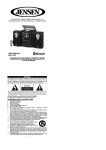
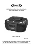
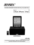
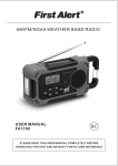
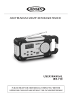
BIG BUTTON TELEPHONE WITH SOS EMERGENCY KEY USER MANUAL SFA3275 SUBSCRIPTION TO CALLER ID SERVICE FROM YOUR LOCAL TELEPHONE COMPANY IS REQUIRED FOR ALL CALLER ID FEATURES TO OPERATE CORRECTLY PLEASE READ THIS USER MANUAL COMPLETELY BEFORE OPERATING THIS UNIT AND RETAIN IT FOR FUTURE REFERENCE IMPORTANT SAFETY INSTRUCTIONS THIS SYMBOL IS TO ALERT YOU THE IMPORTANT OPERATING OR SERVICING INSTRUCTIONS THAT MAY APPEAR IN YOUR USER MANUAL. ALWAYS FOLLOW BASIC SAFETY PRECAUTIONS WHEN USING THIS PRODUCT TO REDUCE THE RISK OF INJURY, FIRE OR ELECTRIC SHOCK. When using your telephone equipment, basic safety precautions should always be followed to reduce the risk of fire, electric shock and injury to persons, including the following: 1. Read and understand all instructions. 2. Follow all warnings and instructions marked on the product. 3. Unplug this product from the telephone line and ac adaptor before cleaning. Do not use liquid or aerosol cleaners. Use a damp cloth for cleaning. 4. Do not use this product near water, for example, near a bath tub, wash bowl, kitchen sink, or laundry tub, in a wet basement, or near a swimming pool. 5. Do not place this product on an unstable cart, stand, or table. The product may fall, causing serious damage to the product. 6. Slots and openings in the enclosure and the back or bottom are provided for ventilation to prevent overheating. These openings must not be blocked or covered. The openings should never be blocked by placing the product on a bed, sofa, rug, or other similar surface. This product should never be placed near or over a radiator or heat register. This product should not be placed in a built-in installation unless proper ventilation is provided. 7. This product should be operated only from the type of power source indicated on the marking label. If you are not sure of the type of power supply to your home, consult your dealer. 8. Do not allow anything to rest on the power cord of the ac adaptor. Do not locate this product where the cord will be abused by persons walking on it. 9. Always plug the ac adaptor into an outlet that is easily accessible and near to the equipment. 10. Never push objects of any kind into this product through enclosure slots as they may touch voltage points or short out parts that could result in a risk of fire or electric shock. Never spill liquid of any kind on the product. 11. Do not disassemble this product. Take it to a qualified service technician or service center when repair work is required. Opening or removing covers may expose you to voltage or other risks. Incorrect reassembly can cause electric shock when the appliance is subsequently used. 12. Unplug this product from the wall outlet and refer to qualified service personnel under the following conditions: a) When the power supply cord or plug is damaged or frayed. b) If liquid has been spilled into the product. c) If the product has been exposed to rain or water. d) If the product does not operate normally by following the operating instructions. Adjust only those controls that are covered by the operating instructions. Improper adjustment of other controls may result in damage and may require extensive work by a qualified technician to restore the product to normal operation. e) If the product has been dropped or the enclosure has been damaged. f) If the product exhibits a distinct change in performance. 13. Avoid using a telephone during a lightning storm. There may be a remote risk of electric shock from lightning. 14. Do not use the telephone to report a gas leak in the vicinity of a leak. 15. Never install telephone wiring during a lightning storm. 16. Never install telephone jacks in wet locations unless the jack is specifically designed for wet locations. E-1 17. 18. Never touch uninsulated telephone wires or terminals unless the telephone line has been disconnected at the network interface. Use caution when installing or modifying telephone lines. For optimal performance it is recommended that this product is used on a conventional phone line. Performance may vary with VOIP or other digital services. SAVE THESE INSTRUCTIONS THE FCC WANTS YOU TO KNOW: CONSUMER INFORMATION If requested by the telephone company, inform them as follows: FCC Registration No . . . . . . . . . . . . . . . . . . . . . . . . . . . . . . 2BFTE07BSFA3275 Ringer Equivalence . . . . . . . . . . . . . . . . . . . . . . . . . . . . . . . . 0.7B The particular telephone line to which the equipment is connected. a) This equipment complies with Part 68 of the FCC rules and the requirements adopted by the ACTA. On the bottom of this equipment is a label that contains, among other information, a product identifier in the format US:AAAEQ##TXXXX. If requested, this number must be provided to the telephone company. b) An applicable certification jacks Universal Service Order Codes (USOC) for the equipment is provided (i.e., RJ11C) in the packaging with each piece of approved terminal equipment. c) A plug and jack used to connect this equipment to the premises wiring and telephone network must comply with the applicable FCC Part 68 rules and requirements adopted by the ACTA. A compliant telephone cord and modular plug is provided with this product. It is designed to be connected to a compatible modular jack that is also compliant. See installation instructions for details. d) The REN is used to determine the number of devices that may be connected to a telephone line. Excessive RENs on a telephone line may result in the devices not ringing in response to an incoming call. In most but not all areas, the sum of RENs should not exceed five (5.0). To be certain of the number of devices that may be connected to a line, as determined by the total RENs, contact the local telephone company. [For products approved after July 23, 2001, the REN for this product is part of the product identifier that has the format US:AAAEQ##TXXXX. The digits represented by ## are the REN without a decimal point (e.g., 03 is a REN of 0.3). For earlier products, the REN is separately shown on the label.] e) If this equipment SFA3275 causes harm to the telephone network, the telephone company will notify you in advance that temporary discontinuance of service may be required. But if advance notice isn't practical, the telephone company will notify the customer as soon as possible. Also, you will be advised of your right to file a complaint with the FCC if you believe it is necessary. f) The telephone company may make changes in its facilities, equipment, operations or procedures that could affect the operation of the equipment. If this happens the telephone company will provide advance notice in order for you to make necessary modifications to maintain uninterrupted service. E-2 g) Should you experience trouble with this equipment, please contact Service Department, Spectra Merchandising International, Inc at 4230 North Normandy, Chicago IL 60634, hotline: 1-800-777-5331 for repair or warranty information. If the equipment is causing harm to the telephone network, the telephone company may request that you disconnect the equipment until the problem is resolved. h) Please follow instructions for repairing if any (e.g. battery replacement section); otherwise do not alternate or repair any parts of device except specified. i) Connection to party line service is subject to state tariffs. Contact the state public utility commission, public service commission or corporation commission for information. j) NOTICE: If your home has specially wired alarm equipment connected to the telephone line, ensure the installation of this SFA3275 does not disable your alarm equipment. If you have questions about what will disable alarm equipment, consult your telephone company or a qualified installer. k) This equipment is hearing aid compatible. NOTICE: According to telephone company reports, AC electrical surges, typically resulting from lightning strikes, are very destructive to telephone equipment connected to AC power sources. To minimize damage from these types of surges, a surge arrestor is recommended. Applicable for Coin or Pay Phone Only To comply with state tariffs, the telephone company must be given notification prior to connection for customer-owned coin or credit card phone. In some states, the state public utility commission, public service commission or corporation commission must give prior approval of connection. FCC PART 15 COMPLIANCE This device complies with Part 15 of the FCC Rules. Operation is subject to the following two conditions: (1) this device may not cause harmful interference, and (2) this device must accept any interference received, including interference that may cause undesired operation. Note: This equipment has been tested and found to comply with the limits for a Class B digital device, pursuant to Part 15 of the FCC Rules. These limits are designed to provide reasonable protection against harmful interference in a residential installation. This equipment generates, uses and can radiate radio frequency energy and, if not installed and used in accordance with the instructions, may cause harmful interference to radio communications. However, there is no guarantee that interference will not occur in a particular installation. If this equipment does cause harmful interference to radio or television reception, which can be determined by turning the equipment off and on, the user is encouraged to try to correct the interference by one or more of the following measures: Reorient or relocate the receiving antenna. Increase the separation between the equipment and receiver. Connect the equipment into an outlet on a circuit different from that to which the receiver is connected. Consult the dealer or an experienced radio/TV technician for help. WARNING: Changes or modifications to this equipment not expressly approved by the party responsible for compliance could void the user’s authority to operate the equipment. E-3 DEAR FIRST ALERT® CUSTOMER We have taken great care to make sure that your product was in perfect working order when it left our factory. It has been designed to give you many years of enjoyment and trouble free operation. Read this manual before operating this unit to become familiar with its features and obtain the performance that will bring you continued satisfaction for many years. For future reference, record the serial number in the space provided. Model Number: SFA3275 Serial Number: __________________ CONTENTS OF YOUR PRODUCT SFA3275 Telephone Set Coiled Handset Cord (9 feet) Line Cord (5 feet) 2 Position Desktop Stand User Manual (English and Spanish) PROTECT YOUR FURNITURE!! This system is equipped with non-skid rubber ‘feet’ to prevent the product from moving when you operate the controls. These ‘feet’ are made from non-migrating rubber material specially formulated to avoid leaving any marks or stains on your furniture. However certain types of oil based furniture polishes, wood preservatives, or cleaning sprays may cause the rubber ‘feet’ to soften, and leave marks or a rubber residue on the furniture. To prevent any damage to your furniture we strongly recommend that you purchase small self-adhesive felt pads, available at hardware stores and home improvement centers everywhere, and apply these pads to the bottom of the rubber ‘feet’ before you place the product on fine wooden furniture. E-4 LOCATIONS OF CONTROLS 1. 2. LCD Display (One-Touch Memory Buttons: M1 to M4) 3. 4. Phonebook Button Handset/Speaker/Ringer Volume Control 5. Speakerphone Button with Status Indicator Speakerphone Microphone Redial/Pause Button Delete/Set ButtonHandset Jack Hold/Mute Button Flash Button SOS Button Handset Cradle Caller-ID and Up Button & Down Button 6. 7. 8. 9. 10. 11. 12. 13. 14. Keypad 15. Speaker 16. Handset Holder 17. Hook Switch E-5 18. Handset 19. Handset (coiled) Cord 20. Battery Cover Screw 21. Battery Compartment Cover 22. Deskstop Stand Mounting Slots 23. Telephone Line Jack 24. Handset Jack 25. Keyholes for Wall Mounting 26. Desktop Stand (2-position) INSTALLATION CONNECTING THE TELEPHONE 1. Plug one end of the telephone line cord into the TEL.LINE JACK at the back of the telephone base. 2. Plug the other end of the telephone line cord into the wall outlet. 3. Plug one end of the coiled cord into the handset's modular jack. 4. Plug the other end of the coiled cord into the HANDSET JACK on the left side of the telephone. INSTALLING BACKUP BATTERIES Your telephone requires four AAA (UM-4) batteries (not included) for backup. When the “ ” icon appears on the display or if the display gets dim, replace all the batteries with four fresh “AAA” size (UM-4) ones. Note: The telephone numbers in memory are stored in non-volatile flash memory which does not require battery power for backup. INSTALLING BATTERIES INTO THE TELEPHONE 1. Unscrew the BATTERY COVER SCREW and open the BATTERY COMPARTMENT COVER located on bottom of cabinet. 2. Insert four DC1.5V “AAA” size (UM-4) alkaline batteries (not included) into the Battery Compartment following the polarity markings as indicated in the compartment. 3. Snap the BATTERY COMPARTMENT COVER back into place and tighten the BATTERY COVER SCREW. BATTERY CARE Be sure that the batteries are installed correctly. Wrong polarity may damage the unit. Do not mix old and new batteries. Do not mix alkaline, standard (carbon-zinc) or rechargeable (nickel-cadmium) batteries. E-6 If the unit is not to be used for an extended period of time, remove the batteries. Old or leaking batteries can cause damage to the unit and may void the warranty. Do not try to recharge batteries not intended to be recharged; they can overheat and rupture (Follow battery manufacturer’s directions). Do not dispose of batteries in fire, batteries may explode or leak. MOUNTING THE DESKTOP STAND Two different mounting options are available for the DESKTOP STAND. Insert the stand into the corresponding slots on the bottom of the telephone for a more comfortable viewing angle. OPTION A will tilt the phone at a 49 degree angle, and OPTION B is at a 30 degree angle. ATTACHING THE STAND 1. Place the main unit, keypad side down on a soft stable surface. 2. For OPTION A (49 degree angle), refer to the following diagram: Align and insert the “A” tabs on the stand into the wider openings of the DESKTOP STAND MOUNTING SLOTS located on the bottom of the SFA3275. When the hooks are properly inserted, carefully slide the DESKTOP STAND forward with both hands until it reaches the end of the slots and locks into place. 3. Turn the unit over, and place it on a firm flat surface. Note: The same procedures applies for mounting OPTION B (30 degree angle), just align and insert the “B” tabs on the stand into the base. DETACHING THE STAND 1. Place the main unit, keypad side down on a soft stable surface. 2. To remove the STAND for either mounting option, refer to the following diagram: Carefully slide the DESKTOP STAND backward horizontally as shown with both hands until it aligns with the wider openings of the DESKTOP STAND MOUNTING SLOTS. Carefully pull the STAND out of the base openings. E-7 MOUNTING THE PHONE ON A WALL The phone may be mounted on a suitable wall or other vertical surface by following the directions below. Select an area of the wall where you would like to hang your phone and make sure there are no pipes or electrical cables located behind the wall in this area. Caution: Cables and wiring to electrical switches and sockets usually run vertically in the wall. Do not mount your phone directly above or below an electric switch or socket unless you are sure that the cables will not be damaged when attaching the screws (screws and plastic anchors are not included). 1. 2. 3. 4. Drill two holes vertically, one above the other, 3-1/4” (83mm) apart, and leave the screw heads protruding from the wall by about 3/16” (5mm). Note: Adjust the amount that the screw heads protrude from the wall so that the phone sits flat against the wall when mounted. Press and lift out the HANDSET HOLDER and rotate it 180 degrees to expose the hanging tab. Place the HANDSET HOLDER back into place so it will hold the HANDSET in place when the phone is mounted on the wall. Plug one end of the TELEPHONE LINE CORD into the TELEPHONE LINE JACK at the bottom of the base. Plug the other end of the LINE CORD into the wall plate jack, then align the base's KEYHOLE SLOTS with the screws and slide the telephone unit downward to secure it. E-8 SETUP MENU There are 11 different functions in the setup menu for this telephone. You can press and hold the SET BUTTON to enter the setup menu and press it repeatedly to access each of the function one by one as follows: SETUP FUNCTION Language LCD Contrast Enter Date & Time Local Code Prefix Ringer Melody FUNCTION DESCRIPTIONS Select the desired display language from 10 options: English (default), French, Spanish, Portuguese, Polish, Italian, Swedish, German, Dutch, Turkish Adjusts the contrast level of the LCD panel for easy reading. Options are: 1 – 5 and the default is 4. Enter the time and date information Set the 5 digit local code Set the 3 digit prefix Select your favorite ringer sound from 16 melodies Set the ringer volume level from 1 to 7 or turn it OFF completely Set the flash time. Flash Options are: 100, 200, 300, 400, 600 (default), 900 ms Set the interdigit pause time Pause Options are: 1.2, 2.4 (default), 3.6 seconds Dial in DTMF/PULSE Set the dialing mode between tone (default) or pulse. Adjust the tone dialing format precisely if there are difficulties in accessing certain DTMF controlled functions such as phone banking. DTMF duration We recommend you to keep the default settings and do not try to modify them if DTMF (tone) dialing and operations are normal. Ringer Volume SETTING THE DISPLAY LANGUAGE 1. Press and hold the SET BUTTON to enter the setup menu. 2. Select the desired display language from 10 options English (default), French, Spanish, Portuguese, Polish, Italian, Swedish, German, Dutch and Turkish using or and confirm with the SET BUTTON. 3. The display now shows to “SET LCD CONTRAST”, you can refer to next section to set the contrast level of the LCD DISPLAY or pick up the HANDSET to exit the setup mode. SETTING THE CONTRAST OF THE LCD DISPLAY 1. Press and hold the SET BUTTON to enter the setup menu. 2. Press the SET BUTTON again. “SET LCD CONTRAST” is shown with the current “contrast” setting flashing. 3. Press or to select the desired contrast level and confirm with the SET BUTTON. 4. Pick up the HANDSET to exit the setup mode. SETTING THE DATE AND TIME 1. Press and hold the SET BUTTON to enter the setup menu. 2. Press the SET BUTTON repeatedly until the current “year” digits are flashing. 3. Select the correct year using the or and confirm with the SET BUTTON. The current “month” digits will now flash in the display. 4. Select the correct month using the or and confirm with the SET BUTTON. The current “date” digits will now flash in the display. 5. Select the correct date using the or and confirm with the SET BUTTON. The day of week will be set automatically. The current “hour” digits will now flash in the display. 6. Select the correct hour using the or and confirm with the SET BUTTON. The current “minute” digits will now flash in the display. 7. Select the required minutes using the or and confirm with the SET BUTTON. E-9 8. Pick up the HANDSET to exit the setup mode. SETTING THE LOCAL AREA CODE If you set up the area code, for example: 773-1234567, when you receive a call from the same area, the caller ID will skip the area code and show the last telephone number (1234567) only. 1. Press and hold the SET BUTTON to enter the setup menu. 2. Press the SET BUTTON repeatedly until “SET LOCAL CODE” is shown and the first of the five available digits is flashing. 3. Press or to select the desired number and confirm with the SET BUTTON. 4. Repeat step #3 to set up the other numbers of your area code. 5. Pick up the HANDSET to exit the setup mode. SETTING THE DIALING PREFIX The prefix code is used for adding a specific number in front of the dialing numbers of caller ID, phonebook and pre-dial, especially when used behind an office PABX system, in order to get an outside line. 1. Press and hold SET BUTTON to enter the setup menu. 2. Press the SET BUTTON repeatedly until “PREFIX” is shown and the first of the three available digits is flashing. 3. Press or to select the desired number and confirm with the SET BUTTON. 4. Repeat step #3 to set up the other numbers of your required prefix code. 5. Pick up the HANDSET to exit the setup mode. SETTING THE RINGER MELODY 1. Press and hold the SET BUTTON to enter the setup menu. 2. Press the SET BUTTON repeatedly until “RINGER MELODY” is shown with the current “Melody No.” flashing. 3. Select the desired melody from 01 to 16 using the or and confirm with the SET BUTTON. 4. Pick up the HANDSET to exit the setup mode. SETTING THE RINGER LEVEL 1. Press and hold the SET BUTTON to enter the setup menu. 2. Press the SET BUTTON repeatedly until “RINGER VOL.” is shown with the current “Ringer Vol Level” flashing. 3. Select the desired ringer volume level from 1 (Lo) to 7 (Hi) or OFF using the or and confirm with the SET BUTTON. 4. Pick up the HANDSET to exit the setup mode. SETTING THE FLASH TIME 1. Press and hold the SET BUTTON to enter the setup menu. 2. Press the SET BUTTON repeatedly until “FLASH TIME” is shown with the current “Flash Time” setting flashing. 3. Select the required flash time from 100, 200, 300, 400, 600 and 900 ms using the or and confirm with the SET BUTTON. 4. Pick up the HANDSET to exit the setup mode. SETTING THE PAUSE TIME 1. Press and hold the SET BUTTON to enter the setup menu. 2. Press the SET BUTTON repeatedly until “PAUSE TIME” is shown with the current “Pause Time” setting flashing. 3. Select the required pause time from 1.2, 2.4 and 3.6 seconds using the or and confirm with the SET BUTTON. 4. Pick up the HANDSET to exit the setup mode. SETTING THE TONE/PULSE DIALING MODE 1. Press and hold the SET BUTTON to enter the setup menu. 2. Press the SET BUTTON repeatedly until “DIAL IN DTMF” is shown flashing. 3. Select the required dialing mode between “DTMF” (tone) and “PULSE” using the or and confirm with the SET BUTTON. 4. Pick up the HANDSET to exit the setup mode. E-10 TELEPHONE OPERATION DIALING A CALL 1. Pick up the HANDSET or press the BUTTON (the OFF HOOK INDICATOR will light steadily) and wait for a dial tone. The LCD DISPLAY will show “LINE IN USE” on the bottom line. 2. Press the numbers on the KEYPAD for the telephone number you wish to dial. The display will show the numbers you entered on the KEYPAD. If you dial a number over 16 digits long, it will show the last 16 digits only. 3. When you have completed your call, hang up the HANDSET or press the BUTTON again to release the telephone line and end the call. 4. The LCD display will show the elapsed call time during the call on the top line and the total call time at the end of the bottom line. Note: It is possible to switch from a handset conversation to a speakerphone conversation by pressing the BUTTON and placing the HANDSET into the HANDSET CRADLE. PRE-DIALING A PHONE NUMBER 1. Enter the telephone number on the KEYPAD. 2. To modify a number, press the DELETE BUTTON for each digit to be corrected. 3. Pick up the HANDSET, or press the BUTTON and the displayed number will be dialed out automatically. RECEIVING A CALL When you receive a call, the telephone rings and the RINGER INDICATOR flashes. The LCD DISPLAY will show the CALL# and the caller telephone number if you have subscribed to Caller ID. This feature allows you to decide to pick up the phone or not depending on who is calling. If you want to talk to the caller: 1. Pick up the HANDSET or press the BUTTON to answer the call. 2. At the end of the call, return the HANDSET to the cradle or press the BUTTON again. SPEAKER VOLUME CONTROL You can adjust the speakerphone volume using the VOL (VOLUME CONTROL) BUTTON. The current volume level setting is indicated by a series of “ooooooo” on the LCD DISPLAY. The lowest volume setting is one “o” and highest volume setting is “oooooooo”. The default speaker volume is on the highest volume setting. HANDSET VOLUME CONTROL You can also adjust the handset volume to the desired listening level using the VOL (VOLUME CONTROL) BUTTON. The current volume level setting is indicated by a series of “oooo” in the LCD DISPLAY. The lowest volume setting is one “o” and highest volume setting is “oooo”. The default handset volume is “ooo”. RINGER VOLUME CONTROL You can adjust the ringer volume to the desired level using the VOL (VOLUME CONTROL) BUTTON. 1. When the phone is in the “on hook” status or while the phone is ringing, press and hold the VOL BUTTON for 3 seconds and the LCD DISPLAY will show “RINGER VOL” and the current level from 1 (minimum) to 7 (maximum) or OFF. 2. Tap the VOL BUTTON repeatedly until the desired ringer level is obtained. REDIAL There are a total of 16 redial memories so that the last 16 entered numbers can be recalled and E-11 dialed out at any time. 1. Press the REDIAL BUTTON and the most recent call record “01”, with the dialed number and calling time is shown. 2. Press the REDIAL BUTTON repeatedly to find older records down the list. 3. If the desired record is found, you can lift the HANDSET or press the BUTTON to dial it out automatically. 4. If you want to delete a record, tap the DEL BUTTON and “ERASED ?” is shown. Press the DEL BUTTON again to confirm. 5. When all records have been reviewed, “TOP OF LIST” will be shown. The LCD DISPLAY will revert to normal display in 15 seconds automatically after the last key press. Note : The last number dialed manually (up to 20 digits long) can be redialed. PAUSE You can insert a 2.4 second pause while dialing or storing a number into memory in order to access custom and telebanking services, long distance, etc. Press REDIAL BUTTON at the desired point within the number and a “P” will be inserted. Press REDIAL BUTTON again if an additional 2.4 second pause is needed. CALL WAITING AND FLASH (subscription to Call Waiting service may be required) Many special telephone services, such as Call Waiting, require a switch hook signal. If you have the Call Waiting service, you can put a call on hold and take a second incoming call on the same line by pressing FLASH BUTTON. Press FLASH BUTTON again to alternate between the two callers. Notes: If you do not have any special phone services requiring a switch hook signal, pressing FLASH BUTTON may disconnect the current call. The recommended flash time for most service provider is 600 ms but you may adjust it in the setup menu any time you need. HOLD WITH MUTE/MUSIC AND EXTENSION RELEASE MUTE In handset talk mode, press the HOLD BUTTON to mute the call and “MUTE ON” is shown. This function is to prevent the person on the other end of the line from hearing what you are saying. You can continue to hear the person on the other end. HOLD In handset talk mode, if you press the HOLD BUTTON and hang up the HANDSET or in hands-free mode, the line will be held with music. The LINE STATUS INDICATOR will flash. In both cases, the call parties cannot hear each other. While in hold mode, you may: Press the HOLD BUTTON again to release and resume the conversation; Pick up the HANDSET while in speakerphone mode to release and continue the conversation; Use the or BUTTONS to change the music melody from 16 selections; Use VOL BUTTON to change the music volume in the same way as in speaker volume control. HOLD RELEASE While a line is on hold, you can release it by: Picking up the HANDSET; Pressing the BUTTON; Pressing the HOLD BUTTON again; Pick up another phone connected to the same extension. HEARING AID COMPATIBILITY (HAC) This unit is compatible with inductively coupled hearing aids and cochlear processors. Adjust your hearing aid’s or processor’s “T-switch” to the “T” position. E-12 THE PHONE BOOK (DATABANK) STORING NUMBERS AND NAMES IN THE PHONE BOOK (UP TO 80 ENTRIES) 1. Press the BUTTON and “ADD SEARCH ” is shown. 2. Press and “PLS INPUT NAME” is shown. 3. Enter the required name with a maximum of 16 letters and confirm with the BUTTON. “PLS INPUT NUMBER” will then be shown. 4. Enter the required telephone number with a maximum of 20 digits using the numeric KEYPAD and confirm with the BUTTON. 5. The “MEMORY COUNTER” at the top left corner of the LCD DISPLAY will increase by one to show the total number of entries. 6. You can repeat steps #3 to #4 to enter more entries or press BUTTON twice to exit. Note: When the all memory location is full, “MEMORY FULL” will be displayed. How to enter names The number buttons are also inscribed with letters for entering the name. By repeatedly pressing the appropriate button, uppercase letters and the space character can be entered. Button Letters/symbols ================================================= 1 [Space character] 2 A..................................................................................B C 3 D..................................................................................E F 4 G................................................................................. H I 5 J...................................................................................K L 6 M................................................................................. N O 7 P..................................................................................Q R S 8 T.................................................................................. U V 9 W.................................................................................X Y Z * [Space character]..................................................... 0 [Space character] # [Space character] Incorrect entry can be deleted with the DEL BUTTON. TO REVIEW THE PHONE BOOK MEMORY 1. Press the BUTTON and “ADD SEARCH ” is shown. 2. Press and “PLS INPUT NAME” is shown. 3. Enter the initial letter of the name of the person you wish to call using the KEYPAD. After a short time, the display will show the first stored telephone number with this initial letter. You can now search for further numbers under this letter by pressing or . Notes: If no telephone number is stored, the display will show “EMPTY”. After you have viewed all the entries in memory, the display will show “END OF DATABANK”. TO DIAL THE DISPLAYED TELEPHONE NUMBER FROM THE PHONE BOOK MEMORY 1. Select the telephone number in the phone book you want to call until it is shown on the LCD DISPLAY. 2. Press the BUTTON or pick up the HANDSET and the displayed telephone number will be dialed out automatically. E-13 TO EDIT THE PHONE BOOK MEMORY 1. Press the BUTTON and “ADD SEARCH ” is shown. 2. Press and “PLS INPUT NAME” is shown. 3. Enter the initial letter of the name of the person you wish to call using the KEYPAD. After a short time, the display will show the first stored telephone number with this initial letter. Select the required location from the phone book by pressing or . 4. Press the BUTTON, the cursor will be flashing after the last character of the name of the selected entry. 5. Press the DEL BUTTON to eliminate unwanted character or press the KEYPAD to insert more character(s). 6. After changing the name, press BUTTON to edit the phone number, “PLS INPUT NUMBER” will then be shown. 7. Press DEL BUTTON to delete a digit or press the KEYPAD to insert more number(s) and confirm with the BUTTON. 8. You can repeat steps #2 to #7 to edit more names and numbers and or press BUTTON twice to exit. HOW TO DELETE A PHONE BOOK ENTRY 1. Press the BUTTON and “ADD SEARCH ” is shown. 2. Press and “PLS INPUT NAME” is shown. 3. Enter the initial letter of the name of the person you wish to call using the KEYPAD. After a short time, the display will show the first stored telephone number with this initial letter. Select the required location from the phone book by pressing or . 4. Press and hold the DEL BUTTON for about two seconds to eliminate the current entry. The display will show “ERASED” as confirmation. ONE-TOUCH MEMORIES STORING NUMBERS IN THE ONE-TOUCH MEMORY LOCATIONS WITH PHOTOS This telephone has four One-Touch Memories: M1 to M4. Once a number has been stored in each of these memory locations, you only need a single press to make the call. The transparent memory button cap can be flipped open, so you can insert a thumbnail photo of the person whose number is stored in that location. The thumbnail photo must not exceed 7/8” wide x 11/16” high (22 wide x 17 high mm) in size. 1. 2. 3. 4. Press and hold one of the One-Touch Memories, say M1, for about 2 seconds until “DDRN MEMORY” is shown. You must release the button as soon as “DDRN MEMORY” appears, otherwise it will disappear. Enter the required telephone number with a maximum of 20 digits using the NUMBER PAD. Press M1 BUTTON to confirm. The number is now saved in the M1 memory location. Repeat steps #1 to #3 and use M2 to M4 BUTTONS to save more numbers in M2 to M4 memory locations. TO DIAL FROM ONE-TOUCH MEMORIES 1. Pressing the desired memory button (M1 to M4). The saved phone number will be displayed and dialed out automatically in hands-free mode. 2. Otherwise, you may lift the HANDSET and press the desired memory button (M1 to M4) to dial out the number. E-14 ONE-TOUCH SOS EMERGENCY MEMORY TO STORE AN EMERGENCY NUMBER 1. While the phone is in the “on hook” status, enter your desired emergency telephone number. 2. Press the FLASH BUTTON and the LCD DISPLAY will show “DDRN MEMORY” for about 8 seconds. 3. Before “DDRN MEMORY” disappears, press the SOS BUTTON and the LCD DISPLAY will show “#”. 4. Press # BUTTON of the KEYPAD to confirm. TO DIAL FROM THE SOS MEMORY 1. Press the SOS BUTTON to dial out the stored emergency number automatically in hands-free mode. 2. Otherwise, you may lift the HANDSET and press the SOS BUTTON dial out the number. AUTO-ANSWER PRESET MEMORIES TO STORE AUTO-ANSWER NUMBERS 1. While the phone is in the “on hook” status, enter your desired auto-answer telephone number. 2. Press the FLASH BUTTON and the LCD DISPLAY will show “DDRN MEMORY” for about 8 seconds. 3. Before “DDRN MEMORY” disappears, press one of the dialing keys 1 to 5 of the KEYPAD and the LCD DISPLAY will show “#”. 4. Press # BUTTON of the KEYPAD to confirm. 5. Repeat steps #1 to #4 to store up to 5 auto-answer numbers. AUTO-ANSWER IN SPEAKERPHONE MODE 1. When one of the preset auto-answer numbers is received, the unit will turn on speakerphone mode automatically after 2 rings. 2. You may now talk up to 15 minutes only unless you press one of the dialing keys (1-9, * or #) on the KEYPAD to cancel the time limit. THE CALLER ID FEATURE IMPORTANT NOTES In order to utilize the Caller ID features, you must subscribe to Caller ID service through your local phone company. There are fees for Caller ID services, and it may not be available in all areas. This product can provide information only if both you and the caller are in areas offering Caller ID service, and if both telephone companies use compatible equipment. BASIC CALLER ID OPERATIONS This telephone can store up to 76 incoming calls. If an incorrect, invalid or incomplete Caller ID signal is received, the display shows “LINE ERROR”. If only the caller’s phone number is received, the display shows the caller’s phone number with the time and date it was received. The “NEW” icon will appear. If both the caller’s name and phone number are received, the display shows the caller’s E-15 name and phone number, with the time and date it was received. The “NEW” icon will appear. If the caller’s name has more than 16 characters, only the first 16 characters will be displayed. If the name and number are not available due to the caller’s privacy restriction, the display shows “PRIVATE” with the call’s time and date received and the “NEW” icon will appear. If the name and number are not available, the display will show UNAVAILABLE with the call’s time and date received and the “NEW” icon will appear. If a long distance call message is received, the display will show “LONG DISTANCE” with the call’s time and date received and the “NEW” icon will appear. If the Caller ID memory is full, the oldest data will be removed on a first-in/ first-out basis. If the Caller ID information received duplicates another call in memory, the time/date will be updated and the “REP” (REPEAT) icon will light. If the incoming call is unanswered, the LCD DISPLAY will revert to the new call counter, current time and date if no key is pressed within 25 seconds. VIEW THE CALLER ID RECORD 1. Under on hook status, press CLID to review more recent calls. The CALL# will increase. After you view the most recent data in memory, the display will show “END OF LIST”. 2. Press Caller ID to review older calls. The CALL# will decrease. After you view the oldest data in memory, the display will show “TOP OF LIST”. 3. If the data in memory is being reviewed for the first time, the “NEW” icon will light. 4. If no key is pressed within 15 seconds, the LCD DISPLAY will revert to the new call counter, current time and date. ERASE THE CALLER ID RECORD 1. Select the required Caller ID record using the Caller ID or Caller ID . 2. To delete a single Caller ID record, press DELETE BUTTON once. The display will show “ERASED ?”. Press DELETE BUTTON again and the data of that call will be erased, and the CALL# and Caller ID information will be updated. 3. To delete all records, press and hold DELETE BUTTON until the display shows “ALL ERASED ?”. Press DELETE BUTTON again and the data of all calls will be erased. The new call counter will become zero, and the current time and date will be displayed. CALL BACK (REDIAL) FROM THE CALLER ID MEMORY 1. Select the required Caller ID record by pressing Caller ID or Caller ID . 2. Pick up the HANDSET or press the BUTTON to dial it out automatically. TROUBLESHOOTING GUIDE If you experience difficulties in the use of this music system please check the following or call 1-800-777-5331 for Customer Service. No dial tone Check that all phone cord connections (including the coiled handset cord) and AC Adaptor are securely plugged into the telephone & wall jack. Check that the phone is in the correct dialing mode, Touch-Tone or Pulse Setting. Plug another phone into the jack to make sure your jack and phone service is functioning properly. Call will not dial out or dials very slowly Check that the phone is in the correct dialing mode, Touch-Tone or Pulse Setting No audible ringer E-16 You may have too many extensions on your line. Try unplugging a few devices. Having too many telephones and/or accessories can also create problems such as low ringer volume or impaired quality during calls. Noise, Static, Interferences while using the handset A filter may be required for homes with DSL line or near Radio towers. Caller ID information does not show Make sure you have subscribed to Caller ID service through your local phone company. CARE AND MAINTENANCE 1. 2. 3. 4. 5. 6. Clean your phone with a damp (never wet) cloth. Solvent or detergent should never be used. If your phone stops working, check to be certain that all modular plugs are properly “snapped” into their jacks. If the phone still doesn’t work and you have other telephones installed in your home, check to see if they are working. If they are, try using your telephone on another outlet. If it still doesn’t work, it is more than likely that there is a problem with your telephone. In this case, return the unit for service in accordance with the instructions on your warranty card. DO NOT CALL THE TELEPHONE COMPANY SINCE YOU MAY BE RESPONSIBLE FOR CHARGES FROM THEM. CHARGES FROM THE TELEPHONE COMPANY ARE NOT COVERED BY THE TERMS AND CONDITIONS OF THE WARRANTY. If other telephones in your house have also stopped working, the problem is most likely with your telephone line service. Do not return your telephone for service since most likely there is nothing wrong with it. You should however, consult with your telephone company to see if there has been any interruption to your line service. If it is determined that your telephone is malfunctioning, FCC requires that it be disconnected from the modular outlet until the problem has been corrected. Always have your unit repaired by an experienced technician or return it for service to address listed in WARRANTY AND SERVICE section. © 2014 BRK Brands Inc. All rights reserved. First Alert® is a registered trademark of the First Alert Trust. At Spectra, environmental and social responsibility is a core value of our business. We are dedicated to continuous implementation of responsible initiatives with an aim to conserve and maintain the environment through responsible recycling. Please visit us at http://www.spectraintl.com/green.htm for more information on Spectra’s green initiatives or to find a recycler in your area. E-17 1 YEAR LIMITED WARRANTY AND SERVICE VALID IN THE U.S.A. ONLY This product is manufactured, distributed or sold by SPECTRA MERCHANDISING INTERNATIONAL, INC., official licensee for this product. All right, title and interest to use the “First Alert” logo trademarks and the “First Alert” trade dress are exclusively licensed by BRK Brands, Inc. and are used under license from BRK Brands, Inc.. Please contact SPECTRA’s Service Department for questions/comments, warranty, support, or service related to this product. SPECTRA MERCHANDISING INTERNATIONAL, INC. warrants that this product 1) is free from defects in materials and workmanship and 2) conforms to its specifications for a period of 1 year from the date of original customer purchase and provided the product is utilized within the U.S.A. This warranty is not assignable or transferable. Our obligation under this warranty is the repair or replacement of the defective unit or any part thereof, except batteries, when it is returned to the SPECTRA Service Department, accompanied by proof of the date of original consumer purchase, such as a duplicated copy of a sales receipt. You must pay all shipping charges required to ship the product to SPECTRA for warranty service. If the product is repaired or replaced under warranty, the return charges will be at SPECTRA’s expense. There are no other express warranties other than those stated herein. This warranty is valid only in accordance with the conditions set forth below: 1. The warranty applies to the SPECTRA product only while: a) It remains in the possession of the original purchaser and proof of purchase is demonstrated b) It has not been subjected to accident, misuse, abuse, improper service, usage outside the descriptions and warnings covered within the owner’s manual or non-SPECTRA approved modifications c) Claims are made within the warranty period 2. This warranty does not cover damage or equipment failure caused by electrical wiring not in compliance with electrical codes or SPECTRA owner’s manual specifications, or failure to provide reasonable care and necessary maintenance as outlined in the owner’s manual. 3. Warranty of all SPECTRA products applies to residential use only and is void when products are used in a nonresidential environment or installed outside the United States. This warranty gives you specific legal rights, and you may also have other rights which vary from state to state. TO OBTAIN SERVICE please remove all batteries (if any) and pack the unit carefully and send it prepaid by insured parcel post or UPS to SPECTRA at the address shown below. IF THE UNIT IS RETURNED WITHIN THE WARRANTY PERIOD shown above, please include a proof of purchase (dated cash register receipt) so that we may establish your eligibility for warranty service and repair of the unit without cost. Also include a note with a description explaining how the unit is defective. A customer service representative may need to contact you regarding the status of your repair, so include your name, address, phone number and e-mail address to speed the process. IF THE UNIT IS OUTSIDE THE WARRANTY PERIOD, please include a check for $25.00 to cover the cost of repair, handling and return postage. All out of warranty returns must be sent prepaid. It is recommended that you contact SPECTRA first at 1-800-777-5331 or by e-mail at [email protected] for updated information on the unit requiring service. In some cases the model you have may be discontinued and SPECTRA reserves the right to offer alternative options for repair or replacement. E-18 SPECTRA MERCHANDISING INTERNATIONAL, INC. 4230 North Normandy Avenue, Chicago, IL 60634, USA. 1-800-777-5331 To register your product, visit the link below on the website to enter your information. http://www.spectraintl.com/wform.htm 0714 Printed in China E-19