1
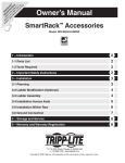
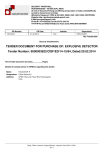
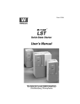
QuickLock BIG
User Manual
Version 04/2014
Sold by:
Rausch Electronics USA, LLC. 4757 Innovation Way Chambersburg, PA 17201
Service: (717) 263-8093 | Office: (717) 709-1005 | Fax: (717) 709-1009 | www.repipetech.com | [email protected]
IMPORTANT DISCLAIMER:
This manual is subject to change without notice. Updates can be obtained online at
www.repipetech.com. This manual does not guarantee the product will work properly.
Contact a RAUSCH Certified Installer to ensure proper installation. The following are
important disclaimers to consider before using the QuickLock BIG system.
1.
QuickLock BIG installations are to be performed only by trained and qualified
personnel, using adequate and safe equipment.
2.
Read and follow the instructions, as described in this manual before
attempting installation.
3.
Prior to beginning the installation, verify that all the equipment and
components involved are undamaged and in proper working condition.
4.
QuickLock BIG is designed for and must only be used in municipal sewer,
storm sewer and potable water environment. For all other applications, please
consult Rausch prior to use.
5.
Do not use QuickLock BIG in broken pipes with protruding objects.
6.
Verification of lines inner diameter / I.D. must be known as accurate as
possible in order to ensure the correct sleeve is used. Refer to the Technical
Data Sheet at the end of this manual.
7.
If after reading this manual you have any questions or concerns, please
contact Rausch USA.
Version: 04/24/2014
2
Contents
1. About this document ............................................................................................... 4
1.1 Regulations ................................................................................................................... 4 2. Description of the QuickLock BIG system............................................................ 5
2.1 Intended use ................................................................................................................. 5 2.2 Components and functions ........................................................................................... 6 2.3 Description of the system and procedure .....................................................................7
2.4 Suitability and materials used ....................................................................................... 8
3. How to use the system ............................................................................................ 9
3.1 Preparation.................................................................................................................... 9 3.1.1 Inspecting the pipe ......................................................................................... 9 3.1.2 Preparing the damaged area .......................................................................... 9 3.2 Equipment and materials ............................................................................................10 3.3 Installing QuickLock BIG ............................................................................................ .12 3.4 Serial installation .........................................................................................................17 3.5 Tool maintenance........................................................................................................18 4. Appendix 1 Technical data sheet.......................................................................... 20
Version: 04/24/2014
3
1. About this document
These instructions supplement the basic QuickLock user manual.
They specifically describe how to use the QuickLock BIG system.
Please observe the aforementioned user manual with its general instructions on using the QuickLock
system.
1.1
Regulations
Regulations vary on a state by state basis.
Version: 04/24/2014
4
2. Description of the Quick Lock BIG system
2.1
Intended use
Cross-section
The QuickLock BIG sleeve is a product for permanently and tightly sealing leaking pipe joints, radial
cracks, and longitudinal cracks in large pipes and manholes of DN 800 and larger.
The sleeve is 20 cm wide.
The sealed area (between the circumferential seals) is approximately 12 cm.
(The distance between the circumferential seals is approximately 14 cm. However, these are
pulled together when the jacket is expanded so that the sealed area is 12 cm wide.)
The system is made from AISI 316L stainless steel of grade 1.4404 and
an EPDM compression seal.
The materials used are permanently resistant in municipal wastewater systems.
Their suitability must be ascertained for use in industrial or polluted wastewater.
Version: 04/24/2014
5
2.2
Components and functions
System components
Stainless steel sleeve consisting of two or
more sections
Locking screws (4x)
Sliding blocks (4x)
Rubber jacket (1x)
Version: 04/24/2014
6
2.3 Description of the system and procedure
QuickLock BIG consists of:
•
•
•
•
•
A 316L stainless steel sleeve
An EPDM rubber jacket
The damaged section is repaired and sealed by
permanently clamping the steel sleeve in place.
This exerts a pressing force which compresses the
rubber jacket against the inside of the pipe.
The area between the circumferential seals (1) is
completely sealed.
When the steel sleeve is manufactured, it is rolled tighter
than the diameter of the pipe to be repaired.
Two toothed strips are punched into the sleeve, on the
left and right.
•
•
•
In each toothed strip there is a lock.
The lock is for clamping the steel sleeve.
The lock can only move in one direction and stops
the sleeve from contracting once it has been
expanded.
The lock moves along the toothed strip (to the left as
shown here).
This means that the steel sleeve can only expand in one
direction.
The lock prevents it from contracting again.
The increments are only 0.65 mm, which means that the
sleeve is almost infinitely adjustable.
How it works: The middle gear wheel is on a spring and
acts as a ratchet for the others.
Version: 04/24/2014
7
2.4 Suitability and materials used
2.4.1 Properties of the pipe to be repaired
QuickLock BIG can be used to repair all common types of pipe:
•
•
•
•
•
•
Vitrified clay pipes
Concrete pipes
PVC pipes
Glass-reinforced PVC pipes
Cast iron pipes
Steel pipes
2.4.2 Stainless steel
The QuickLock BIG sleeve is made of 316L stainless steel of grade 1.4404. This grade of stainless
steel is characterized by its high corrosion resistance.
•
•
•
QuickLock BIG is designed for use in municipal wastewater systems.
For use with industrial wastewater or where the wastewater contains high levels of chloride salts,
the required corrosion resistance must be ascertained.
316L stainless steel of grade 1.4404 may be used up to a chloride concentration of 600 mg/l.
2.4.3 EPDM rubber
Like the steel sleeve, the thermoset polymer EPDM jacket is designed for municipal wastewater
systems. EPDM is characterized by its excellent physical properties and its resistance to aging,
ozone, weathering and environmental effects, alkalis, and various chemicals.
EPDM is unsuitable, or only suitable with restrictions for:
•
•
•
•
Solvents
Ethers, esters, ketones, methylene chloride
Animal and vegetable fats, oils, fuels
Concentrated fruit juice, oxidizing acids
2.4.4 Industrial use
QuickLock is also suitable, with certain restrictions, for industrial use, depending on the properties of
the fluids.
Note: Before using QuickLock in industrial, non-municipal wastewater systems, the corrosion
resistance of the 316L stainless steel and the EPDM sleeve must be verified.
Version: 04/24/2014
8
3. How to use the system
3.1
Preparation
3.1.1 Inspecting the pipe
Before using QuickLock BIG, the pipe must be inspected to ascertain whether it can be repaired with
the system.
See the main user manual.
3.1.2 Preparing the damaged area
Before installing the QuickLock BIG sleeve, the damaged area must be prepared as follows:
Manually remove all protruding obstacles (seals, roots)
Manually even out any joint misalignments of more than 0.5 cm using special mortar.
In some circumstances, using epoxy resin for reprofiling may only be possible when the concrete
is wet, but not soaked through. Generally, we do not recommend it.
Recommended mineral mortars:
Sealt-Tec P
Ergelit S100
Ombran MHP 15
Flowing water (infiltration) always poses problems.
Therefore, stop the infiltration in advance using plugging mortar.
Even out any corroded, porous inner pipe surfaces in the area to be sealed using special mortar.
Version: 04/24/2014
9
3.2
Equipment and materials
Installation tools
(Supplied by Rausch USA)
Four clamping tool sections
2 x with screw unit
2 x with seat
(1) Spindle
For pre-tensioning the sleeve
(2) Clamping screws
For clamping the sleeve and
pressing it in place
(3) Retaining lug
For attaching the tool to the
sleeve
Depending on the pipe diameter, the
retaining lugs (3) on the installation
tool may have to be changed.
These parts are supplied with the
tools.
The retaining lugs must be mounted
as illustrated (3).
DN 800/900
Version: 04/24/2014
> DN 1000
10
Required accessories
Make sure you have the necessary tools.
If necessary we can provide the tools for sale or hire.
Lubricant
Ruler or tape measure
8 mm Allen key
17 mm socket
Crayon
Interchangeable socket wrench (or 17 mm ratchet wrench)
Plastic or rubber mallet
Talcum powder
Laser for measuring the damaged area (optional, not shown)
Pneumatic socket wrench (optional for rapid installation)
Version: 04/24/2014
11
3.3
Installing QuickLock BIG
Installation
Bringing in the sleeve
Do not assemble the sleeve.
Bring in the sleeve via the manhole entrance.
Putting the sleeve together
Join the sleeve sections together so that the
tracks punched out of them are on the outside.
Place the sliding blocks in the tracks.
Secure the sliding blocks with the locking screws.
Adjust the sleeve to the smallest diameter and
tighten the locking screws.
Applying talcum powder to the rubber jacket
Apply talcum powder to the inside of the rubber
jacket.
Version: 04/24/2014
12
Preassembling the sleeve
Pull the jacket over the sleeve
until the tapered rubber edge
lies on the steel sleeve.
The preassembled sleeve is rolled so tightly that
it can be taken into the pipe and turned around
there.
Marking out the position
On one side of the damage, at a distance of 10
cm from the center (the sleeve length is 20cm),
mark out the position of the sleeve all the way
around the circumference of the pipe.
Positioning the sleeve
Position the sleeve so that the tapered edge of
the rubber faces against the direction of flow.
Direction of flow
Version: 04/24/2014
13
Aligning the sleeve
Align the sleeve to the marking in the pipe.
Turn the sleeve so that the locking screws are
roughly level on the left and right sides of the
pipe.
The sleeve must always be installed
perpendicular to the axis of the pipe.
When using a spirit level, the pipe slope must be
adjustable.
Attaching and securing the clamping tools
The clamping tools on the left and right sides are
identical.
However, the clamping tools are aligned
differently on the left and right: one of them
points up and the other points down.
Attach the two parts of each clamping tool as
close together as possible.
Tighten the spindles to hold the clamping tools in
place.
Expanding the sleeve
Start on one side.
Loosen the locking screws.
Tighten the spindle to about half way until the
sleeve is pressed against the pipe.
When expanding the sleeve, make sure it
opens up evenly.
The easiest way to do this is to look at the
holes on the left (1) and right (2).
Continue on the other side:
Loosen the locking screws here too.
Tighten the spindle to about half way.
Version: 04/24/2014
14
Aligning to the marking
Just before the sleeve is pressed to the pipe,
align it once again to the marking
or the axis of the pipe.
Repositioning the clamping tools
Tighten the locking screws.
Loosen the spindles.
Reposition the two parts of each clamping tool as
close together as possible.
Fasten them with the clamping screws.
Clamping
Keep working on both sides of the sleeve
alternately:
Loosen the locking screw.
Tighten the two clamping screws
evenly. Use the holes as a guide.
Tapping in
While you are doing this, occasionally tap all the
way round the sleeve with the mallet so that the
tension is evenly distributed.
Note
The spindle is only designed for expanding the
sleeve. The sleeve is clamped using the two
clamping screws on the left and right of the tool.
Version: 04/24/2014
15
Compressing to 12 mm / 13 mm
Keep clamping until the added material (rubber
jacket + metal) is less than
12 mm for DN 800 – DN 1300
13 mm for more than DN 1300
Measure all the way round (< 12 mm/13 mm).
Eccentric expansion (if necessary)
For minor joint misalignments, bends, or
persisting leaks, the sleeve can be expanded
eccentrically using the second clamping screw.
Note: If the sleeve is expanded too eccentrically,
the tools can become jammed.
Use the holes as a guide.
Tightening the locking screws
Make sure that the sleeve has reached its final
state.
Tighten the locking screws using the ratchet.
Version: 04/24/2014
16
Removing the clamping tools
Loosen the clamping screws of the tools.
Remove the tools.
he
T QuickLock BIG sleeve now forms a tight
and reliable seal.
Version: 04/24/2014
17
3.4
Serial installation
For longer areas of damage, serial installation is sometimes possible.
We can supply a 25 cm wide rubber overlap, with each half between the actual seal and the pipe
wall.
The distance between the sleeves should be at
least 40 mm in order to leave enough space for the
clamping tools.
When two BIG sleeves are installed in series, the
tapered rubber edge on each one faces outwards.
If more than two sleeves are installed in series, the
tapered rubber edge must be trimmed off on the
middle ones.
Version: 04/24/2014
18
3.5
Tool maintenance
Maintenance
The spindles and clamping screws must be
treated with high-pressure lubricant (Metaflux
lubricating metal) after each use.
Damaged retaining lugs can be replaced with
the aid of the two socket screws.
DN 800/900
Version: 04/24/2014
> DN 1000
19
4 Appendix 1
Technical data sheet
Centre line
Rubber thickness : S Rubber
316L
Sleeve length L
∅ - Min/max pipe ID
System
Total : Dg
Wall thickness 316L : S
∅ - 316: da/DA ∅ -
Seal height: Hn
Diameter
316L : da / DA
Total ∅ : Dg
(inc. seal)
Distance between seals: AN
Tapered rubber edge
Suitable for pipes
from / to
Stainless steel sleeve
Rubber jacket
Sleeve
length
Total diameter,
rolled
Pipe ID
min.
Pipe ID
max.
Wall
thickness
s
316L pipe
rolled da
Max. expanded
diameter DA
Rubber
thickness
Height of
seals
Distance
between
seals
Total
weight
mm
mm
mm
mm
mm
mm
mm
mm
mm
mm
mm
kg
Designation:
L
Dg
DN min
DN max
S 316L
da
DA
S Rubber
Hn
An
QuickLock BIG
sleeve DN
x parts
800
2
200
738
770
830
3
710
815
3
11
140
17.9
900
2
200
838
870
930
3
810
915
3
11
140
19.7
1000
2
200
938
970
1030
3
910
1015
3
11
140
21.6
1100
2
200
1038
1070
1130
3
1010
1115
3
11
140
23.7
1200
2
200
1138
1170
1230
3
1110
1215
3
11
140
25.7
1300
2
200
1238
1270
1330
3
1210
1315
3
11
140
27.6
1400
3
200
1338
1370
1430
4
1310
1415
3
11
140
1500
3
200
1438
1470
1530
4
1410
1515
3
11
140
1600
3
200
1538
1570
1630
4
1510
1615
3
11
140
1700
3
200
1638
1670
1730
4
1610
1715
3
11
140
1800
3
200
1738
1770
1830
4
1710
1815
3
11
140
Version: 04/24/2014
20