1
2 The WSI system emulating the human brain
In order to function, the HICANN chips need
twelve different voltages. Ten of them are
generated on the powerboards, the two remaining
are provided by an external supply, as they may
need high currents, which the powerboards
cannot supply. From these power supplies the
voltages are routed to the HICANN chips
through the main pcb. The monitoring of the
voltages is conducted by 24 microcontrollers6
situated on the main pcb, each of the
microcontrollers monitoring the voltages of two
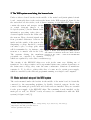
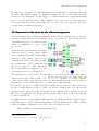
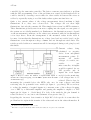
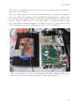
Figure 2: Model of WSI system reticles. The circuits delivering the voltages
composition. From bottom to top:
contain FETs7, which are needed to switch the
Cooling fins, wafer with bracket, main
printed circuit board (main pcb), four voltages on or off. The FETs can either close the
FPGA boards5. The FETs7 necessary to circuits to apply the voltages or open the circuits
gate the supply voltages are situated
to disconnect the voltages. There are measuring
under the bracket in the middle, the
PICs6 are the 24 small black squares points before and after the FETs, the values of
distributed in the corners of the main which are monitored by the corresponding
pcb.
(Taken
from
the
WSI
microprocessor. If the values surpass a certain
documentation [5].)
threshold, the microcontroller switches the FETs
off, so that the reticles have no more voltages [5]. The different voltages applied to
each reticle can be switched on and off manually as well, for instance when starting the
system. At this point the Raspberry Pi becomes relevant for the system.
2.2 Why to exchange the former board with a Raspberry Pi
When the first WSI system was set up two
years ago, the CPU8 module chosen to run the
clkboard programme was a taskit Stamp9G20.
The processor comes along with an evaluation
board, which provides interfaces necessary to
communicate with the other parts of the WSI
system. Today, this hardware setup is
somewhat outdated. There are faster processors
with a smaller periphery, which still provide all
required interfaces and which are at the same
time less expensive. One of the best total
6
7
8
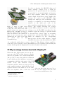
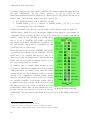
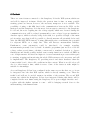
Figure 3: Raspberry Pi – size as big as a
credit card. The header P1 is the one at
the very left, equipped with pins. This
header is used with the ribbon cable.
dsPIC33FJ128GP710 - „PIC“.
Field Effect Transistor.
Central Processing Unit – „processor“.
3