1
G7204, G7208
and G7211 FORCED
CONVECTION OVENS
USERS INSTRUCTIONS
SECTION 1 - GENERAL DESCRIPTION
SECTION 2 - LIGHTING and OPERATIONS
SECTION 3 - COOKING HINTS
SECTION 4 - CLEANING and MAINTENANCE
These appliances have been CE-marked on the basis of compliance with the Gas Appliance Directive,
EMC and Low Voltage Directive for the Countries, Gas Types and Pressures as stated on the Data
Plate.
These appliances MUST BE installed by a competent person in compliance with the INSTALLATION AND
SERVICING INSTRUCTIONS and National Regulations in force at the time. Particular attention MUST be paid
to the following:
I.E.E. Regulations for Electrical Installations
Electricity at Work Regulations
Gas Safety (Installation & Use) Regulations
Health and Safety at Work Act
Furthermore, if a need arises to convert the unit for use with another gas, a competent person must be
consulted. Those parts which have been protected by the manufacturer MUST NOT be adjusted by the User.
Users should be conversant with the appropriate provisions of the Fire Precautions Act and the requirements of
the Gas Safety Regulations. in particular the need for regular servicing by a competent person to ensure the
continued safe and efficient performance of the appliance.
WARNING - TO PREVENT SHOCKS, ALL APPLIANCES WHETHER
GAS OR ELECTRIC, MUST BE EARTHED!
Upon receipt of the User's Instruction manual, the installer should instruct the responsible person(s) of the
correct operation and maintenance of the appliance.
This equipment is ONLY FOR PROFESSIONAL USE, and shall be operated by QUALIFIED persons. It is the
responsibility of the Supervisor or equivalent to ensure that users wear SUITABLE PROTECTIVE CLOTHING
and to draw attention to the fact that, some parts will, by necessity, become VERY HOT and will cause burns if
touched accidentally.
WEEE Directive Registration No. WEE/DC0059TT/PRO
At end of unit life, dispose of appliance and any replacement parts
in a safe manner, via a licenced waste handler.
Units are designed to be dismantled easily and recycling of all
material is encouraged whenever practicable.
Falcon Foodservice Equipment
HEAD OFFICE AND WORKS
Wallace View, Hillfoots Road, Stirling. FK9 5PY. Scotland.
SERVICELINE CONTACT PHONE: 01438 363 000
FAX: 01438 369 900
T100635 Ref. 1
SECTION 1 - GENERAL DESCRIPTION
The G7204, G7208 and G7211 are forced convection
ovens utilising an energy saving re-circulation
principle. The heated air from the two burners flows
in ducts behind the side and over the top of the oven
chamber to be sucked down into the fan and
circulated with the air inside the oven. The air inside
the oven is further heated as it flows along the
boundary walls of the oven chamber before being
drawn over the food being cooked in the oven.
The system provides a product of comparable quality
to that of food prepared in a natural convection oven.
In most cases this is achieved at a lower temperature
without manipulation and in a shorter time. The oven
also incorporates a cook and hold facility to allow the
user to roast meat at a low temperature with
automatic changeover to a hold condition whereupon
the product will remain at a constant tenderising
temperature until required for carving.
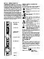
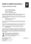
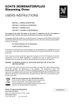
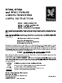
Mains indicator neon
Ignition safety
lockout indicator
Fan mode switch
Temperature Control
ON/OFF Switch
Heat Required Indicator
Cook Mode Switch
Timer
SECTION 2 - CONTROLS and OPERATION
2.1 CONTROLS
The controls are mounted on a panel at the RH side
of the oven as shown below. These consist of :
1. Red neon indicates that power is being
fed to the unit.
2. White neon warning that burner ignition
has failed.
3. Fan mode switch for Cool Down and
Heat-up operation.
4. Cook thermostat controls temperature
during Cook heating cycle. This is also
the on/off switch.
5. Amber lamp indicates chamber
temperature is below the set point.
6. Cook mode switch for Cook Only or
Cook/Hold operation.
7. Timer with audible buzzer. Buzzer
operates in Cook Only mode.
8. Oven light switch with automatic spring
return action. Light illuminates when
button is pressed in and is a feature of
the E7204 and E7208 models only.
The oven is fitted with a door microswitch. This will
shut off power to the fan and element when door is
opened during a heating cycle.
The hold thermostat is concealed within the controls
compartment and is pre-set to a temperature of 80oC.
Note: A power on/off switch for the operational
controls is integral to the cook thermostat (4).
To switch the controls on, the knob must be rotated
clockwise from the off position.
2.2 HEATING THE OVEN
2.2.1 SWITCHING ON
Note
The ignition system is protected by a safety lock-out
device. If the controls lock out, this will be indicated by
the white ignition warning light being lit. Re-ignition
cannot be achieved until 5 seconds have elapsed.
1. Switch on mains. Red neon (1) should illuminate.
2. Close oven door.
3. Ensure fan mode switch (3) is set to 'Heat-up
operation'.
4. Select cook mode (6) - COOK ONLY or
COOK and HOLD.
Light Switch
Figure 1
2.2.2 If COOK ONLY mode is selected:
1. Set timer (7) to a required time or to manual on
position (marked MAN on dial).
2. Turn cook thermostat (4) to chosen temperature
whereupon the ignition sequence will proceed as
follows: an initial flame detector and purging period
of 6 seconds occurs then gas flows to the burners
whilst sparks are generated simultaneously at the
burner electrodes. The burners should light
instantly and smoothly. If the burners do not light
within the safe period of 5 seconds then the flame
detectors will signal the controller to go into the
safety lockout state (2). Turn cook thermostat (4) to
OFF position and wait at least 5 seconds.
Then turn the cook thermostat (4) to the chosen
cooking temperature. The burner should now light.
2.2.3 If COOK and HOLD mode is selected:
1. Set timer (7) to required cooking time.
2. Turn cook thermostat (4) to chosen temperature
whereupon ignition sequence will proceed as
detailed in Section 2.2.2.
3. At the end of cook time, oven control will be
switched from cook to hold thermostat.
Note
If cook thermostat is turned to such a low setting that
the gas extinguishes, wait at least 6 seconds before
turning to a higher setting or the controls will go to
lockout. Should this occur, turn cook thermostat to
OFF position and wait 6 seconds before setting
desired temperature.
2.2.4 If HOLD ONLY is required:
1. Set cook mode switch (6) to Cook and Hold.
2. Set timer knob (7) in upright position.
Remember to allow oven to heat up before inserting
the food requiring to be kept warm.
2.2.5 SWITCHING OFF
1. Turn Cook thermostat (4) fully anti-clockwise to off
position. This will also cut power to all controls.
2. Isolate at main supply.
2.3 RAPID COOLING OF THE OVEN
If the oven has been operating at a much higher
temperature than required for the next load, the rapid
cooling facility should be utilised to cool the oven to
the desired value.
1. Open oven doors.
2. Set fan mode switch (3) to cool down.
3. Turn thermostat (4) to lower setting.
The fan will now run and lower oven temperature.
When oven has cooled, carry out switching on
procedure.
N.B. - If gentle cool down is required keep doors ajar
rather than fully open.
2.4 TIMER
The knob is marked in minutes and should be set to
the required time when food is placed in the oven.
Turn fully clockwise and back to desired setting.
2.4.1 Cook Only Mode
When set time has elapsed, the elements will be
switched OFF.
Warning buzzer will sound continuously until the
operator switches oven off by turning thermostat (4)
fully anti-clockwise to the Off position or switch timer
to 'MAN'.
Manual On position ('MAN') switches on oven with no
timer setting.
2.4.2 Cook and Hold Mode
When set time has elapsed, oven temperature control
will switch from cook to hold thermostat.
2.5 PRE-HEAT TIME
Allow at least 30 minutes pre-heat from cold
irrespective of desired setting. Insert food quickly
and close doors firmly.
SECTION 3 - COOKING HINTS
SECTION 4 - CLEANING and MAINTENANCE
3.1 G7204 Model
Warning
All four shelves can be used simultaneously. Under
normal circumstances, no manipulation of food
product on the shelves is necessary. Most pastry
items and shallow containers should be prepared at
shelf positions 2, 4,6 and 8, the lowest number being
the top. Frozen multi-portion entree packs should
also be reconstituted at these positions.
When food types of larger dimensions require to be
cooked then shelves should be arranged to suit the
operators requirements.
3.2 G7208 Model
All six shelves can be used simultaneously. Under
normal circumstances, no manipulation of food
product on the shelves is necessary. Most pastry
items and shallow containers should be prepared at
shelf positions 1, 3, 5, 7, 9 and 11, the lowest number
being the top.
Frozen multi-portion entree packs should also be
reconstituted at these positions. When food types of
larger dimensions require to be cooked then shelves
should be arranged to suit the operators
requirements.
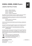
3.3 G7211 Model
A rack and trolley are provided for quick and easy
loading. The rack is supplied with 10 shelves to be
used in any number of permutations and can be
loaded on the trolley prior to insertion into the oven.
To load the rack into the oven, proceed as follows:
a) Open doors and present trolley to oven. Ensure
trolley rails align with those in oven.
c) Apply wheel brakes.
d) Push rack from trolley into oven and ensure rack is
fully home.
e) Undo wheel brakes and pull back trolley.
f) Close oven doors.
BEFORE ANY CLEANING IS UNDERTAKEN,
ISOLATE THE POWER SUPPLY FROM THE
MAINS. THE APPLIANCE MUST NOT BE
CLEANED WITH A JET OF WATER, OR STEAM
CLEANED.
The internal and external unit surfaces are stainless
steel. A glass panel is mounted within the doors of
G7204 and G7208 models.
General cleaning of surfaces to remove light staining
and spillage may be achieved by washing with a
slightly damp cloth and soap detergent. This practice,
if carried out daily, will prevent build-up of stubborn
baked-on deposits. Wipe surfaces down with a soft
cloth rinsed in fresh water which has been squeezed
free of excess liquid.
Stubborn stains and baked-on deposits are best
removed by nylon scouring pads or oven spray-on
materials.
The glass panel may be cleaned with proprietary
glass spray-on materials. Cold water must not be
applied to the glass when hot as cracking of the
special toughened panel could occur.
Oven shelves and support grids can be removed for
cleaning. This will also facilitate cleaning of the cavity
walls.
Some internal areas of oven around the fan will not be
accessible to kitchen staff. Since build-up of deposits
in these areas could be detremental to the oven
performance, these should be cleaned periodically by
service personnel.
Falcon Foodservice Equipment or their distributor(s)
can organise a Servicing Contract during which
specialized cleaning can be undertaken.
Service
Contact the AFE Serviceline number on the cover of
this manual.
IN EVENT OF A GAS ESCAPE, ISOLATE AT
SUPPLY. VENTILATE AREA AND CALL GAS
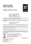
Rack Removal
SUPPLIER.
When removing a loaded rack from the oven, the
NOT SEARCH FOR GAS ESCAPES WITH
handle should be inserted from underside of guide DO
NAKED
FLAMES.
brackets to allow more rack control and to enable a
degree of lift over track wheel stop. When returning
rack to trolley ensure rack engages in catch.