1
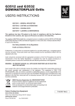
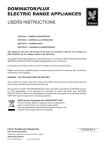
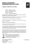
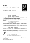
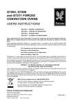
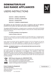
G3478 DOMINATORPLUS
Steaming Oven
USERS INSTRUCTIONS
SECTION 1 - GENERAL DESCRIPTION
SECTION 2 - LIGHTING and OPERATIONS
SECTION 3 - COOKING HINTS
SECTION 4 - CLEANING and MAINTENANCE
This appliance has been CE-marked on the basis of compliance with the Gas Appliance
Directive for the Countries, Gas Types and Pressures as stated on the data plate.
The appliance MUST BE installed by a competent person in compliance with the INSTALLATION AND
SERVICING INSTRUCTIONS and National Regulations in force at the time. Particular attention MUST
be paid to the following:
Gas Safety (Installation & Use) Regulations
Health and Safety at Work Act
Furthermore, if a need arises to convert the appliance for use with another gas, a qualified person must
be consulted. Those parts which have been protected by the manufacturer MUST NOT be adjusted
by the User.
Users should be conversant with the appropriate provisions of the Fire Precautions Act and the
requirements of the Gas Safety Regulations. in particular the need for regular servicing by a
competent person to ensure the continued safe and efficient performance of the appliance.
WARNING - TO PREVENT SHOCKS, ALL APPLIANCES WHETHER GAS OR ELECTRIC,
MUST BE EARTHED.
Upon receipt of the User's Instruction manual, the installer must instruct the responsible person(s) of
the correct operation and maintenance of the Appliance. This equipment is ONLY FOR
PROFESSIONAL USE, and shall be operated by QUALIFIED persons. It is the responsibility of the
Supervisor or equivalent to ensure that users wear SUITABLE PROTECTIVE CLOTHING and to draw
attention to the fact that, some parts will, by necessity, become VERY HOT and will cause burns if
touched accidentally.
WEEE Directive Registration No. WEE/DC0059TT/PRO
At end of unit life, dispose of appliance and any replacement
parts in a safe manner, via a licenced waste handler.
Units are designed to be dismantled easily and recycling of all
material is encouraged whenever practicable.
Falcon Foodservice Equipment
HEAD OFFICE AND WORKS
Wallace View, Hillfoots Road, Stirling. FK9 5PY. Scotland.
SERVICELINE CONTACT
Phone: 01438 363 000
Fax: 01438 369 900
T100789 Ref. 1
SECTION 1 GENERAL DESCRIPTION
Stopcock must be turned ON at all times while oven is in
use. If stopcock is left closed during operation, the well
could boil dry, resulting serious damage to chamber base.
The unit consists of a stainless steel oven chamber with
a side-hinged door and a water well in chamber base.
Water flows in from a rear mounted cistern and the level
is controlled automatically by a ball valve in the cistern.
Oven Hangers, Shelves and Containers
There are two identical hangers that locate upon studs
near top of chamber.
Water in well is heated by a gas burner that is operated
by a control knob on lower front of unit.
Six perforated aluminium shelves are normally supplied.
These slide upon the hanger runners.
Warning: When opening door during normal operation,
steam will escape.
Any number of shelves or containers can be used
according to requirements up to a maximum of six.
The control has a built-in flame failure device to shut off
gas supply to burners in the event of pilot being
extinguished for any reason.
A single 1/1 gastronorm container may be placed upon
each shelf.
A spark igniter is provided to assist with lighting pilot.
SECTION 2 LIGHTING and OPERATIONS
The oven has steam vent in chamber roof and a drain
valve in the base. In addition, a small drain valve is
provided in drip trough below door.
Burner Control
There are four set operating positions as illustrated:
Vent to atmosphere
Single action
door lock pin
(two stage action
option available)
Position 1
Burner and Pilot OFF.
Drip trough
drain cock
Position 2
Pilot Ignition or Pilot ON only.
Pilot sight
glass
Controls
Drain cock
Position 3
Main Burner
FULL FLAME.
Spark igniter
Figure 1
Removable door trough
Water Level
Unit must be installed with a stopcock on water supply
cistern. THE OVEN SHOULD NEVER BE USED EMPTY!
Open stopcock to fill water well through cistern located at
unit rear. Filling should stop automatically when depth in
well reaches 70mm. Water level mark is located at rear of
well.
When oven control is ON, water will heat. When boiling,
well is automatically topped up to maintain correct water
level.
Position 4
Main Burner
LOW FLAME.
Figure 2
Because of in-built safety stop, it is necessary to push
knob in before trying to turn it from OFF to IGNITION and
from IGNITION to OFF.
Between full on and low rate, burner can be regulated as
required. Settings will be determined by experience.
Lighting The Burner
CHECK WATER STOPCOCK IS TURNED ON AND
THAT CHAMBER CONTAINS WATER.
Burner control knob must be pressed in slightly to turn it.
Refer to Figure 2 for control settings.
To Light Pilot
1. Open base cabinet door.
2. Press knob in and turn to ignition symbol.
3. Press and hold knob fully in.
4. Press igniter button and check that spark has lit pilot.
An inspection window is provided in inner front panel.
If pilot does not light, release igniter knob and press in
again.
5. With pilot lit, continue to hold knob in for a further
20 seconds then release.
If pilot goes out, repeat 3, 4 and 5.
To Light Main Burner
6. With pilot lit, turn burner control to full flame position.
Check burner lights from pilot.
7. Close base cabinet door.
SECTION 3 - COOKING HINTS
Heating Up
With burner lit, close cabinet door. Allow oven to heat up
at full flame setting for 20 to 30 minutes until steam emits
rapidly from top vent. The oven is now ready for use and
burner control should be turned back to low flame position
until food is ready to be loaded.
Cooking
a) Load as required. It is preferable to spread this over
several shelves rather than just one.
b) Close oven chamber door. Turn burner control to full
flame setting.
c) When steam is again emitting rapidly at vent, turn
burner control down to maintain cooking without undue
waste of steam.
Food Loading
45kg of potatoes (maximum) can be cooked, spread
evenly over six containers.
20kg (maximum) of steamed pudding can cooked
in individual moulds spread evenly across six containers.
SECTION 4 CLEANING and MAINTENANCE
The oven chamber should be cleaned daily, immediately
after completion of work whilst unit is still warm.
Turn OFF burner and pilot.
Turn OFF water stopcock.
Open base cabinet door. Drain water from well and
cistern into bucket or similar vessel below drain outlet.
Note: Compartment contents are greater than one bucket
full.
Remove containers, shelves and hangers Clean down
compartment using a suitable detergent on a disposable
cleaning cloth. Rinse with clean cloth and warm water.
Close drain valve, refill boiler well and drain. Dry interior
with clean cloth. Drain drip trough and clean it out
thoroughly.
It is better to leave the oven well empty, ready for the next
work day. Arrangements should be made to ensure that
a check is carried out to avoid lighting burner whilst
chamber well is empty. Refer to lighting instructions in
Section 2.
SECTION 5 - SPARE PARTS
The following parts may require replacing during unit life.
Spark ignition lead
Pilot burner assembly (Natural gas)
Pilot burner assembly (Propane gas)
Injector (Natural gas)
Injector (Propane gas)
Door seal
Door handle
Door pin (single action)
Door pin (double action)
Drip tray
Control knob
Shelf