1
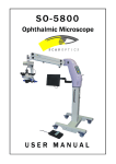
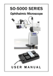
SO-7500 ENT Microscope
User Manual
Page 1 of 21
CONTENTS
PARTS LIST
....................................................................................................................
3
ASSEMBLY INSTRUCTIONS
4
4
6
9
USING THE MICROSCOPE
11
11
12
14
15
16
16
CARE AND MAINTENANCE
17
17
17
17
18
18
TROUBLESHOOTING
........................................................................................................
19
........................................................................................................
Optical head ........................................................................................................
Illumination
........................................................................................................
Power supply ........................................................................................................
Mounting system
............................................................................................
Case ....................................................................................................................
20
20
20
21
21
21
............................................................................................
Floor stand
........................................................................................................
Microscope
........................................................................................................
Connecting cables
............................................................................................
............................................................................................
Articulated arm ........................................................................................................
Panel controls ........................................................................................................
Microscope head
............................................................................................
Lamphouse
........................................................................................................
Positioning the microscope
................................................................................
Sterilisation
........................................................................................................
............................................................................................
Care of the optical head
................................................................................
Power supply ........................................................................................................
Mould pellet replacement
................................................................................
Care of the lamp
............................................................................................
Lamp replacement
...............................................................................................
SPECIFICATIONS
ISSUE NUMBER:
DATE:
3.1
15/08/02
SUPERSEDES ISSUE: 3.0
WRITTEN BY:
DATE:
DATE:
30/07/02
RJK
13/05/99
CHECKED BY:
DATE:
NW
SO-7500 ENT Microscope
User Manual
Page 2 of 21
LIST OF FIGURES
Figure 1
Assembling the floor stand
.................................................................
4
Figure 2
Fixing the floor stand
.............................................................................
5
Figure 3
Attaching the clamp to a mounting surface
Figure 4
Setting the safety cla mp
Figure 5
Assembling the arm
Figure 6
Assembling the microscope
Figure 7
Attaching the handles
Figure 8
Connecting the lamphouse cable
Figure 9
Connecting power cables
.................................................................
10
Figure 10
Adjusting the articulated arm
.................................................................
11
Figure 11
Setting the power supply
.................................................................
12
Figure 12
Adjusting the microscope
.................................................................
14
Figure 13
Adjusting the lamphouse
.................................................................
15
Figure 14
Changing the lamp
.............................................................................
18
.........................................
6
.................................................................
7
.............................................................................
7
.................................................................
8
.............................................................................
8
.....................................................
9
Please read the following information carefully before installing
and using the Scan Optics Ophthalmic microscope. Scan Optics is
responsible for the safety, reliability and performance of the
equipment only if it is used in accordance with these instructions.
ISSUE NUMBER:
DATE:
3.1
15/08/02
SUPERSEDES ISSUE: 3.0
WRITTEN BY:
DATE:
DATE:
30/07/02
RJK
13/05/99
CHECKED BY:
DATE:
NW
SO-7500 ENT Microscope
User Manual
Page 3 of 21
PARTS LIST
MAIN ASSEMBLIES
Clamp Assembly
Articulated Arm Assembly
Microscope Assembly
(includes power supply, mains cable , clamp, vertical pillar)
(includes horizontal arm and adjustable pantograph arm)
(includes yoke, microscope head, lamphouse and cable)
CABLES
12V dc Supply (Battery) Cable
OTHER
Safety Clamp
Microscope eyepiece caps (2)
Microscope handles (2)
Sterilisable handle grips (6)
TOOL KIT
Spare Lamp (1)
Socket keys: 5mm(1), 4mm (2), 3mm (1), 2.5mm (1), 1.5mm (1)
Lens Cloth (1)
ISSUE NUMBER:
DATE:
3.1
15/08/02
SUPERSEDES ISSUE: 3.0
WRITTEN BY:
DATE:
DATE:
30/07/02
RJK
13/05/99
CHECKED BY:
DATE:
NW
SO-7500 ENT Microscope
User Manual
Page 4 of 21
ASSEMBLY INSTRUCTIONS
FLOOR STAND
1.
Remove the pillar, base and clamp mount from the case or carton.
2.
Insert the pillar into the hole. Tighten the two grubscrews using the 5mm socket key found in
the tool kit to fix the pillar in place. Refer to figure 1 (A), (B).
3.
Remove the clamp mount from the case or carton and place it on the pillar. Tighten the two
grubscrews to fix the clamp mount in place. Refer to figure 1 (C), (D).
A
B
C
D
Figure 1
ISSUE NUMBER:
DATE:
3.1
15/08/02
Assembling the floor stand
SUPERSEDES ISSUE: 3.0
WRITTEN BY:
DATE:
DATE:
30/07/02
RJK
13/05/99
CHECKED BY:
DATE:
NW
SO-7500 ENT Microscope
User Manual
Page 5 of 21
4.
To fix the floor stand, screw the knobs down until the stops are resting evenly on the floor.
Refer to figure 2.
5.
Screw the knurled discs down on to the floor stand base to lock the stops. Refer to figure 2.
6.
To unlock the floor stand, screw the knurled discs back up, then unscrew the knobs until the
wheels can move freely.
Figure 2
ISSUE NUMBER:
DATE:
3.1
15/08/02
Fixing the floor stand
SUPERSEDES ISSUE: 3.0
WRITTEN BY:
DATE:
DATE:
30/07/02
RJK
13/05/99
CHECKED BY:
DATE:
NW
SO-7500 ENT Microscope
User Manual
Page 6 of 21
MICROSCOPE
1.
Remove the clamp assembly from the case.
2.
Fix the clamp to the operating table about 40 cm from the head of the table. The clamp may
be fixed on either side of the table. Make sure that the clamp is pressed firmly against the
side of the table before tightening. Refer to figure 3 (A).
M
Alternatively, the clamp may be mounted on any horizontal surface that can
be positioned within 60 cm of the working position, such as a mobile trolley.
M
The clamp may also be attached to the floor stand. When attaching to the
floor stand, first remove the two knobs from the clamp then tilt the clamp
backwards slightly to allow it to fit through the hole in the clamp mount.
Refer to figure 3 (B).
M
The floor stand is clamped vertically to the main clamp assembly at one point
and at two points horizontally. First tighten the vertical clamp firmly then use
the two knobs provided to fix the clamp horizontally to the clamp mount.
Refer to figure 3 (C).
M
It is important that the mounting surface be free from vibration and
movement. Note that in cases where the mounting surface is not rigid,
over-tightening of the vertical clamp will not improve microscope stability. In
this case, add a stiffening plate (such as Scan Optics Table Plate; Cat No.
SO-291) beneath the mounting surface and apply the clamp over the
stiffening plate and the original mounting surface..
A
B
Figure 3
ISSUE NUMBER:
DATE:
3.1
15/08/02
C
Attaching the clamp to a mounting surface
SUPERSEDES ISSUE: 3.0
WRITTEN BY:
DATE:
DATE:
30/07/02
RJK
13/05/99
CHECKED BY:
DATE:
NW
SO-7500 ENT Microscope
3.
User Manual
Tighten the pillar safety clamp at a point midway up the vertical pillar. Refer to figure 4.
Figure 4
4.
Setting the safety clamp
Remove the articulated arm assembly from the case, and place it on the vertical pillar. Make
sure that the arm assembly rests against the pillar safety clamp. Refer to figure 5.
Figure 5
ISSUE NUMBER:
DATE:
Page 7 of 21
3.1
15/08/02
Assembling the arm
SUPERSEDES ISSUE: 3.0
WRITTEN BY:
DATE:
DATE:
30/07/02
RJK
13/05/99
CHECKED BY:
DATE:
NW
SO-7500 ENT Microscope
5.
User Manual
Remove the microscope assembly from the case and locate the microscope assembly in the
end of the arm assembly. Tighten the knob underneath the end of the arm to secure the
microscope in the collet. Refer to figure 6.
Figure 6
6.
Assembling the microscope
Unscrew the silver knobs on top of the microscope mounting block, and insert the handles on
each side. The handles may be positioned individually, indexed at intervals of 45â. Screw the
silver knobs back down to secure the handles. Push the sterilisable covers on to the
microscope handles and focus handle. Refer to figure 7.
Figure 7
ISSUE NUMBER:
DATE:
Page 8 of 21
3.1
15/08/02
Attaching the handles
SUPERSEDES ISSUE: 3.0
WRITTEN BY:
DATE:
DATE:
30/07/02
RJK
13/05/99
CHECKED BY:
DATE:
NW
SO-7500 ENT Microscope
User Manual
Page 9 of 21
CONNECTING CABLES
1.
Pass the lamphouse cable through the cable holders on the arm and attach the plug to the
connector on the top of the pillar. This will ensure the cable does not obstruct the surgeon or
come into contact with the sterile area. Refer to figure 8..
Figure 8
Connecting the lamphouse cable
2.
The Scan Optics SO-7500 Microscope may be connected to either an earthed mains
110/120V or 220/240V ac supply, or a 12V dc supply, or both. Select the appropriate
voltage using the selector located on the front panel of the power supply. If both ac
and dc supplies are connected, the dc supply (for example, a 12V battery) will act as an
emergency backup for mains power. In this case, the microscope will not run from battery
power unless the mains supply fails or is switched off. If mains power is restored, the
microscope will resume using mains power automatically. The mains power switch on the
microscope does not switch the battery off. Refer to figure 9.
3.
Plug the mains power cable into a mains power socket. International safety standards do not
allow the use of an extension cord.
M
The mains power supply must have a protective earth conductor. If
there in no earth conductor, or if the integrity of the earth conductor
arrangement is in doubt, the equipment must be operated from a 12Vdc
power source.
4.
Switch on the mains power supply at the wall socket.
5.
If the power supply is to be connected to a 12-volt dc supply, remove the battery cable from
the case.
ISSUE NUMBER:
DATE:
3.1
15/08/02
SUPERSEDES ISSUE: 3.0
WRITTEN BY:
DATE:
DATE:
30/07/02
RJK
13/05/99
CHECKED BY:
DATE:
NW
SO-7500 ENT Microscope
User Manual
Page 10 of 21
6.
Connect the cable to the 12-volt connector on middle of the front panel on the power supply.
Refer to figure 9.
7.
Connect the red battery clip to the positive battery terminal, and the black clip to the negative
battery terminal. The power supply will not operate if the terminals are reversed
M
Earthing is not required when a 12-volt supply is used alone.
M
The 12 volt supply must be direct current. The power supply will not operate
with 12 volts alternating current.
Figure 9
8.
Where the SO-7500 microscope is used as a companion to the SO-5000, SO-5100 or SO-5600
microscopes, the standard SO-5000 foot switch may be used to change the light intensity of
the lamp. The other foot switch functions will not work on the SO-7500 microscope. The
foot switch may be attached as shown in figure 9 above.
ISSUE NUMBER:
DATE:
Connecting power cables
3.1
15/08/02
SUPERSEDES ISSUE: 3.0
WRITTEN BY:
DATE:
DATE:
30/07/02
RJK
13/05/99
CHECKED BY:
DATE:
NW
SO-7500 ENT Microscope
User Manual
Page 11 of 21
USING THE MICROSCOPE
ARTICULATED ARM
The articulated arm includes a number of features which enable the microscope to be adjusted in
almost any position. Refer to figure 10.
Figure 10
Adjusting the articulated arm
1.
The horizontal arm may rotate about the vertical pillar by unlocking the pillar lock knob (A).
To prevent the arm from rotating, simply lock the knob.
2.
The pantograph (moving) arm may rotate about the end of the horizontal arm by unlocking the
elbow lock knob (B). To prevent the arm from rotating, simply lock the knob.
3.
The amount of friction in the pantograph arm may be adjusted by rotating the handle (C)
located on the side of the pantograph arm. The arm may thus be locked in any position or
alternatively, the amount of friction can be set so that the arm is stable but will move when a
force is applied.
4.
The knob (D) located on the underneath side of the end of the pantograph arm is used to lock
the microscope assembly into place. To release the microscope assembly, simply unscrew the
knob and lift the assembly carefully out of the collet
5.
The knob (E) may be loosened or tightened as necessary to adjust the friction in the yoke
swivel action.
6.
The amount of friction in the microscope tilting action may be changed by tightening or
loosening the socket screws (F) set in the side of the yoke arm. Use the two 4 mm socket
keys provided, holding one steady on the one side while rotating the key on the other side.
ISSUE NUMBER:
DATE:
3.1
15/08/02
SUPERSEDES ISSUE: 3.0
WRITTEN BY:
DATE:
DATE:
30/07/02
RJK
13/05/99
CHECKED BY:
DATE:
NW
SO-7500 ENT Microscope
7.
User Manual
Page 12 of 21
The two knobs (G) may be used to secure the handles (H) in any combination of 8 positions
each. To change the position of the handle, unscrew the corresponding knob until the handle
can be rotated about its axis. Select a suitable position for the handle and tighten the knob to
secure the handle.
PANEL CONTROLS
The panel on the SO-7500 clamp/power supply unit controls the light intensity and provides an
interface for connection to the battery. Refer to figure 11.
Figure 11
Setting the power supply
Power Supply - key to symbols
A
B
C
D
E
Standby button/indicator
NOT USED
Light button/indicator
Intensity button/indicator
Main switch
ISSUE NUMBER:
DATE:
3.1
15/08/02
F
G
H
I
J
K
Resettable circuit breaker (mains side)
Battery cable panel plug
Resettable circuit breaker (battery side)
Foot control input socket
Foot control indicator
NOT USED
SUPERSEDES ISSUE: 3.0
WRITTEN BY:
DATE:
DATE:
30/07/02
RJK
13/05/99
CHECKED BY:
DATE:
NW
SO-7500 ENT Microscope
User Manual
Page 13 of 21
1.
The power supply is switched on by depressing the switch (E) on the front panel. When the
power supply is switched on, the indicator on the switch and the indicator next to the button
(A) on the top panel will light up and an audible 'beep' will be heard. The main switch also
activates cooling fans located in the power supply and in the lamphouse.
2.
When the power supply is switched on, the unit automatically starts on 'standby' mode, as
indicated by the light next to the button (A) on the front panel. In order to activate the power
supply, depress the button (A) a single time. The indicator light will turn off and a single 'beep'
will be heard. The power supply is now ready to operate.
3.
To switch on the light, press the button (C) on the top panel.
4.
The intensity of the light may be varied by selecting the up or down arrow intensity selection
button (D) on the top panel. There are five intensity settings. In the event that the power
supply is switched off or placed on standby, the intensity will revert to the previous setting
when the power supply is switched back on.
5.
A 12V battery may be connected to the power supply as a backup for mains or as an
alternative to the mains supply. To connect a battery, place the crocodile clips on the battery
cable to the appropriate terminals on the battery (red positive +, black negative -) and connect
the battery cable to the panel plug (G) on the front panel.
6.
The SO-5000 foot control may be connected to the front panel by inserting the plug on the end
of the foot control cable into the socket (I) on the front panel. When a pedal on the foot
control is depressed, the indicator (J) on the front panel will light up. This indicates that the
foot control is connected and working properly.
7.
In the event that the power supply fails due to a supply variation, the power supply can be
reactivated with the resettable circuit breakers (F) and (H) on the front panel of the power
supply.
ISSUE NUMBER:
DATE:
3.1
15/08/02
SUPERSEDES ISSUE: 3.0
WRITTEN BY:
DATE:
DATE:
30/07/02
RJK
13/05/99
CHECKED BY:
DATE:
NW
SO-7500 ENT Microscope
User Manual
Page 14 of 21
MICROSCOPE HEAD
1.
To view through the microscope, first remove the protective eyepiece caps, and store them
safely. These protective caps should always be placed back on the microscope when it is not
in use.
2.
In general, the microscope head may be manoeuvred by gripping the side handles and guiding
the microscope to the appropriate spatial position using the various arm articulations available .
Once in position, the friction knobs may be used to lock the microscope in position.
3.
When the microscope has been placed in the appropriate position, the focal length may be
adjusted by rotating the sterilizable focus knob anti-clockwise/right to increase the working
distance or clockwise/left to decrease the working distance. Refer to figure 12.
4.
Diopter adjustment may be undertaken by first viewing through the left (non-adjustable)
eyepiece with the left eye, and focussing on the object by using the focus knob. Then look
through the right (adjustable ) eyepiece with the right eye, and turning the diopter adjustment
ring until the same object is focussed. Refer to figure 12.
5.
Pupillary distance may be adjusted by holding the left and right eyepiece tubes with both
hands, then pushing them together or pulling them apart until perfect binocular vision is
obtained. Refer to figure 12.
Figure 12
ISSUE NUMBER:
DATE:
3.1
15/08/02
Adjusting the microscope
SUPERSEDES ISSUE: 3.0
WRITTEN BY:
DATE:
DATE:
30/07/02
RJK
13/05/99
CHECKED BY:
DATE:
NW
SO-7500 ENT Microscope
User Manual
Page 15 of 21
LAMPHOUSE
1.
The lamphouse position may be adjusted if the light patch is not exactly centred on the centre
of the image viewed through the eyepieces. First, look through the microscope eyepieces and
locate and focus on an object exactly in the centre of the viewing field. Turn the lamp on and
check the location of the light patch relative to the object.
2.
If the light patch needs to be moved left or right, loosen the grub screws which secure the
lamphouse barrel in the mounting block using the 1.5 mm socket key provided. Rotate the
barrel until the light patch is centred, then secure the grub screws once again. Refer to figure
13.
3.
If the light patch needs to be moved up or down, adjust the single screw located on the front
of the lamphouse barrel, located between the mounting block and the microscope. Rotate the
screw clockwise (“in”) to move the light patch down, or anti-clockwise (“out”) to move the
light patch up. Refer to figure 13.
Figure 13
ISSUE NUMBER:
DATE:
3.1
15/08/02
Adjusting the lamphouse
SUPERSEDES ISSUE: 3.0
WRITTEN BY:
DATE:
DATE:
30/07/02
RJK
13/05/99
CHECKED BY:
DATE:
NW
SO-7500 ENT Microscope
User Manual
Page 16 of 21
POSITIONING THE MICROSCOPE
Note that the equipment must be located more than 25 cm away from any medical gas system or
disinfection or degreasing system containing flammable vapour. The power supply must also be
protected from liquid splashes and spills.
STERILISATION
1.
All detachable knobs (focus, handles, handle covers) may be sterilised. However, it may be
convenient for the clamp knobs to be set by a non-sterile person.
2.
The detachable knobs may be sterilised by:
M
M
M
M
boiling
autoclaving
chemical sterilisation
gas sterilisation.
3.
Before sterilising the pillar lock knob, first remove the plastic pad from the end of the shaft.
4.
The anodised and plated metal components can be wiped with any of the normal disinfectants.
5.
The plastic parts and the paintwork of the microscope assembly and the power supply may be
affected by organic solvents. Do not autoclave or wipe with organic solvents such as ether,
xylene or alcohol; to clean use water-based solvents only.
NOTE: National authorities may require the use of specific sterilisation or disinfection
methods.
ISSUE NUMBER:
DATE:
3.1
15/08/02
SUPERSEDES ISSUE: 3.0
WRITTEN BY:
DATE:
DATE:
30/07/02
RJK
13/05/99
CHECKED BY:
DATE:
NW
SO-7500 ENT Microscope
User Manual
Page 17 of 21
CARE AND MAINTENANCE
CARE OF THE OPTICAL HEAD
1.
Cleaning the optical components.
The eyepieces should be checked for cleanliness each time the instrument is used. Surface
dust should be removed with a clean, soft brush. Fingerprints or grease may be removed by
lightly wiping with a cotton cloth or lens tissue moistened with a 70:30 mixture of absolute
alcohol (either ethanol or methanol) and ether. Do not use acetone as it may damage the
surface coating.
2.
Cleaning the plastic parts and paintwork.
Use water based cleaners only.
Do not use any organic solvent such as alcohol, ether or xylene.
3.
Protection against mould.
In hot and humid climates it is common for mould to grow on optical surfaces. Cleaning and
repairing the damage can be expensive and inconvenient. To minimise the risk of mould
forming, do not leave the instrument without eyepiece caps and lens cap inserted and always
store the optical head in a sealed bag containing silica gel desiccant. In tropical climates,
routine annual maintenance of the optical head is recommended.
4.
Do not dismantle.
No parts inside the optical head of the instrument can be serviced by the user. Attempts to
dismantle the optical head or prism cover will make any warranty void.
POWER SUPPLY
1.
In many countries the mains voltage fluctuates widely. Low voltage can greatly reduce the
light output, and high voltage can greatly reduce lamp life. The Scan Optics power supply
automatically provides a constant voltage to the lamp for a wide range of mains power
voltages.
2.
The panel on the power supply may be cleaned by wiping it with a damp cloth. If necessary,
a mild detergent may be used. Do not use abrasive chemicals or agents such as acetone to
clean the panel, as these may damage the protective lexan coating.
MOULD PELLET REPLACEMENT
Scan Optics microscopes are fitted with mould protection which lasts for three years. To replace the
mould pellet, first locate the circular part located between the guide handle and the microscope
objective, on the underside of the microscope head. Undo the 3 grubscrews using the 1.5mm socket
key and remove the part. The anti-mould pellet is adhered to the disc and may be removed and
replaced with a new one. We recommend the use only of pellets supplied by Scan Optics.
ISSUE NUMBER:
DATE:
3.1
15/08/02
SUPERSEDES ISSUE: 3.0
WRITTEN BY:
DATE:
DATE:
30/07/02
RJK
13/05/99
CHECKED BY:
DATE:
NW
SO-7500 ENT Microscope
User Manual
Page 18 of 21
CARE OF THE LAMP
1.
The lamp supplied has a rated average life of 50 hours.
2.
The actual life of the lamp will depend on the intensity setting normally used. The highest
setting is an over-run setting which increases light output but reduces lamp life. Conversely,
running the lamp at the lowest setting will produce a lamp life of greater than 50 hours.
3.
It is strongly recommended that the lamp be replaced as a routine maintenance task, to reduce
the possibility of failure during surgery.
LAMP REPLACEMENT
1.
Always use protective gloves while replacing the lamp as lamp temperatures may be
sufficiently high to burn skin should it come into contact with the glass capsule. Where
possible, allow the lamp to cool before replacing it.
2.
To replace the lamp, first grip the gold rectangular block located beneath the cable gland at the
back of the lamphouse. Pull the block outwards from the long rectangular block to reveal the
lamp assembly. Refer to figure 14.
3.
Grip the lamp holder at the sides where the rectangular cutout is located, and pull the lamp out.
Do not attempt to pull the lamp out by gripping the glass capsule. Refer to figure 14.
4.
Push the new lamp into the socket so that the lamp flange sits flush on the front of the locating
tube. Replace the lamp assembly in the long rectangular block, so that the pins engage in the
sockets and ‘click’ into place. Ensure that the new lamp is free of grease or finger prints
before replacement. Any such marks should be removed with a solvent such as methanol to
avoid reducing lamp life.
Figure 14
ISSUE NUMBER:
DATE:
3.1
15/08/02
Changing the lamp
SUPERSEDES ISSUE: 3.0
WRITTEN BY:
DATE:
DATE:
30/07/02
RJK
13/05/99
CHECKED BY:
DATE:
NW
SO-7500 ENT Microscope
User Manual
Page 19 of 21
TROUBLESHOOTING
1.
2.
3.
4.
SYMPTOM
CAUSE
REMEDY
Lamp does not
operate
Circuit breaker
Check power indicator light on switch,
(if circuit broken, indicator light will not glow)
and reset circuit breaker as necessary.
Mains power failure
Check power indicator light on switch,
use 12V dc battery.
Incorrect voltage
selection
Select correct voltage on front panel.
Battery failure
Check battery voltage and replace or
recharge as necessary.
Battery terminals
incorrectly wired
Wire terminals correctly
(red (+) positive; black (-) negative).
Lamp failure
Replace lamp.
Battery low
Recharge battery.
Lamp blackened
Replace lamp.
Intensity set
low
Increase intensity using panel knob
Mould on optical
surfaces
If mould is evident, return microscope
to Scan Optics for servicing.
Dirty eyepieces
Clean eyepieces.
Mould on optical
surfaces
If mould is evident, return microscope
to Scan Optics for servicing.
Diopter setting
incorrect
Adjust diopter setting with right eyepiece
Pupillary distance
incorrect
Adjust pupillary distance by moving
eyepieces together or apart.
G-clamp loose
Tighten G-clamp.
Mounting surface
unstable
Use more rigid mounting surface.
Microscope head
movement/vibration
Insufficient friction
Check microscope correctly seated in
collet.
Identify & tighten appropriate friction knob.
Lamp dim
Blurred view
Microscope unstable
ISSUE NUMBER:
DATE:
3.1
15/08/02
SUPERSEDES ISSUE: 3.0
WRITTEN BY:
DATE:
DATE:
30/07/02
RJK
13/05/99
CHECKED BY:
DATE:
NW
SO-7500 ENT Microscope
User Manual
Page 20 of 21
SPECIFICATIONS
OPTICAL HEAD
VIEWING SYSTEM
Binocular, stereoscopic
(convergence angle 12o ).
Eyepiece tube inclination 0o .
MAGNIFICATION
Fixed, 10x.
WORKING DISTANCE
Continuously variable, 150-320 mm.
FIELD OF VIEW
27-42 mm, depending on working distance.
REFRACTIVE ERROR
CORRECTION
By focussing right eyepiece !5o
for anisometropia.
FOCUSING
Coarse focus by head movement.
Fine focus by knob control.
INTERPUPILLARY DISTANCE
Adjustable for distance PD range 48 to 75mm.
ILLUMINATION
ALIGNMENT
Coaxial with viewing system.
Direct optical delivery system.
SPECTRAL DISTRIBUTION
Internal UV and IR filters.
LAMP
12V 50W quartz-halogen lamp, rapid change.
High colour temperature 3,300 K for good
tissue definition.
INTENSITY CONTROL
Continuously variable.
AVERAGE
LAMP LIFE
50 hours
ISSUE NUMBER:
DATE:
3.1
15/08/02
SUPERSEDES ISSUE: 3.0
WRITTEN BY:
DATE:
DATE:
30/07/02
RJK
13/05/99
CHECKED BY:
DATE:
NW
SO-7500 ENT Microscope
User Manual
Page 21 of 21
POWER SUPPLY
MAINS POWER
110-240V ac automatically selected input
OUTPUT
Regulated output. Soft start for extended lamp life.
EARTHING
Via earth lead of power cable (green/yellow).
DIRECT CURRENT
12 V dc source optional, automatically selected if
mains voltage fails.
FUSE
Resettable circuit breakers 3A/7A
CABLES
Mains:
Length 5 metres.
Battery:
Length 5 metres.
MOUNTING SYSTEM
CLAMP
Throat 90 mm.
Width 210 mm.
HEAD TILT
-90â to +90â.
HEAD AXIAL ROTATION
Full 360â.
VERTICAL RANGE
Pantograph arm vertical range 690 mm (27.2").
Pillar/horizontal arm vertical range 350 mm (13.8").
Total 1040 mm (40.9").
ARM LENGTH
Pillar to optical axis 1,150 mm (45").
MATERIALS
No ferrous metals to rust or corrode.
CARTON
DIMENSIONS
780 x 560 x 350 mm
(31 x 22 x 14").
WEIGHT
Microscope packed in carton 19 kg (42 lbs).
Floor stand packed in carton 45 kg (99 lbs).
ISSUE NUMBER:
DATE:
3.1
15/08/02
SUPERSEDES ISSUE: 3.0
WRITTEN BY:
DATE:
DATE:
30/07/02
RJK
13/05/99
CHECKED BY:
DATE:
NW