1
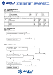
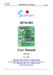
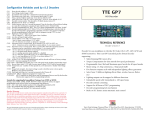
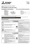
SYSTEM 16 GSM PROGRAMMING GUIDE
User Manual
-1–
Table of Contents
About your Alarm System…………………………………………………………………… 3
Fire Detection…………………………………………………………………………… 3
Testing……………………………………………………………………………………. 3
Monitoring……………………………………………………………………………….. 3
Maintenance……………………………………………………………………………... 3
Installation and Wiring………………………………………………………………………... 4
Control Keypads……………………………………………………………………………….. 7
Keypad Operation……………………………………………………………………………… 8
Away Arming (Leaving-Taking Arm)……………………………………………………….. .8
Home Arming…………………………………………………………………………………….9
Single Zone Arming……………………………………………………………………………. 8
Disarming………………………………………………………………………………………... 8
Remote Arming and Disarming……………………………………………………………. ...9
Remote Monitoring Voice………………………………………………………………………9
Remote Arming/Disarming by Telephone …………………………………………………..9
Voice Message Recording…………………………………………………………………......9
Bypass zone checking………………………………………………………………………… 9
System Setting……………………………………………………………………………….. 10
Factory default setting……………………………………………………………… 10
Reset Alarm System…………………………………………………………………. 11
User Password…………………………………………………………………………12
Installer Password…………………………………………………………………… 12
Access programming………………………………………………………………... 12
Programming wireless detectors………………………………………………….. 12
Set zone type and bell/siren sounds……………………………………………… 12
Set zone to Home Arming…………………………………………………………… 12
Door Chime……………………………………………………………………………. 12
Set user code…………………………………………………………………………..13
Set delay and alarm time……………………………………………………………. 13
Set Telephone Number………………………………………………………………. 13
Set communication protocol and upload report……………....……………….. 13
Set A,B, C Key and remote control ON/Off.……………………………………... 13
Set Remote control ring time and no password option……………………..... 13
Set alarm receiver control and telephone line check ON/OFF………………. 13
Set ADEMCO 4+2 Code……………………………………………………………… 13
Other settings…………………………………………………………………………. 14
GSM Function Setting……………………………………………………………………….. 15
Warning………………………………………………………………………………………….16
-2–
About Your Security System
Your Vstar security system has been designed to provide you with the greatest possible flexibility and
convenience. Read this manual carefully and have your installer instruct you on your system’s operation
and on which features have been implemented in your system. All users of this system should be equally
instructed in its use. Fill out the “System Information” page with all of your zone information and access
codes and store this manual in a safe place for future reference.
Fire Detection
This equipment is capable of monitoring fire detection devices such as smoke detectors and providing a
warning if a fire condition is detected. Good fire detection depends on having adequate number of
detectors placed in appropriate locations. This equipment should be installed accordance with NFPA 72.
Carefully review the Family escape planning guidelines in this manual.
Note: Your installed must enable the fire detection portion of this equipment before
it becomes functional.
Testing
To insure that your system continues to function as intended, you must test your system weekly. If your
system does not function properly, call your installing company for service.
Monitoring
This system is capable of transmitting alarms, troubles & emergency information to a central station. This
system is compatible with ADEMCO Contact ID and ADEMCO 4+2 Express protocol.
Note: The monitoring function must be enabled by the installer before it becomes
functional.
Maintenance
With normal use, the system requires minimum maintenance. Note the following points:
Do not wash the security equipment with a wet cloth. Light dusting with a slightly moistened cloth
should remove normal accumulations of dust.
For other system devices such as smoke detectors, PIR-based motion detectors or IR beam
detectors, consult the manufacturer’s literature for testing and maintenance instructions.
General System Operation
Your security system is made up of a VSTAR control panel, one or more keypads and various sensors
and detectors. The control panel will be mounted out of the way in a utility closet or in a basement.
The metal cabinet contains the system electronics, fuse and backup battery.
Note: Only the installer or service professional should have access to the control panel.
All the keypads have an audible indicator and command entry keys. The LED keypads have a group of
zone and system status lights. The keypad is used to send commands to the system and to display the
current system status. The keypad will be mounted in a convenient location inside the protected premises
close to the entry/exit door
The security system has several zones of are protection and each of these zones will be connected to
one or more sensors (motion detectors, door contacts, glass break detectors, etc.) A sensor in alarm will
be indicated by the corresponding zone lights flashing on a LED keypad.
-3–
Installation and wiring
Wiring Diagram for Control Keypad
AC 1, AC2- It connects to the AC power from transformer. The input power is 16.5V.
BAT +, BAT - - it’s connects to the backup battery (standby battery)
BELL, GND- It connects to the bell/siren, BELL is connecting to positive input of siren, and GND to
negative input of siren.
MIK+, GND, MIK- - It connects to the microphone for monitoring of voice.
AUX- it is output of 14V DC voltage. This voltage is providing power supply for hard wired detectors
sensors.
KEY +, GND, DATA- it connects to hard wired keypad and expand relay output module.
Z1 – Z16- They are hard wired zones, connect to hard wired detectors and sensors.
LIN1, LIN2- Connect to telephone line
TEL 1, TEL2- Connect to telephone.
WDT- It’s power ON light
SIGN- It’s GSM Signal Indicators. When system communicated with GSM cellular network, this
indicator is flicking.
SIM- It’s SIM card slot which is placed with SIM card.
-4–
8 way Relay Outputs Module Wiring Diagram
8 way relay outputs module should connect with KEY, DATA, GND in parallel of hard
wired keypad. The function of relay outputs module is remotely control electronic
device, send alarm signal to trigger DVR to record video.
Wiring of Power Supply
Connection of transformer: Input AC220V 2 red wires connecting directly transformer, AC 16.5V black
wires need connect to AC1, AC2.
DC 12V Standby battery connection: Red wire need to connect BAT +, Black wire need to connect BAT-.
Wiring of wired detectors
The wired zones with EOL design which can provide protection for the wired zones to be cut or
short-circuit.
There are two connection methods:
1.
Normally Closed: connecting a 2.7K EOL resistor in series to the terminal detector of the loop of
-5–
each zone; connecting the other end of the resistor to the wired zone.
2.
Normally Opened: connecting a 2.7K EOL resistor in parallel connection to the terminal detector of
the loop of each zone.
Note: EOL resistors need to connect in the detectors, not the control panel (wired
zones).
Wiring power supply for wired detectors
Connecting the Positive (+) of wired detector to the AUX; connecting the Negative (-) to the GND of
control panel.
Note: connecting the un-used wired zones with 2.7K EOL resistor connection,
otherwise the corresponding zone indicator will keep lighting, so that you can not
Arming the system.
Wiring the BELL/Siren
The Positive (+) of Bell/siren should connect to BELL; the Negative (-) should connect to GND of alarm
panel.
Wiring the telephone line
The exterior line should connect to LIN1, LIN2.
TEL1 and TEL 2 should connect to telephone.
Wiring the voice microphone
The Positive(+) of microphone should connect to MIK+, the Negative(-) should connect to GND, the
Signal should connect to MIK.
Wiring the hard wired keypad
Opening the keypad: use a screw driver to open the plastic hole of the back cover upside of the keypad.
-6–
Note: The wires from the keypad to alarm panel is up to 150 meters, 4 keypad can
be connected in series; to avoid destroy of keypad, the tamper can be connect to
the wired zones.
Control Keypad and Indicator LED Light
Keypad display symbols:
②---ARM Zone Light
①---Function Indicator Light
④---Number Key
⑤---Shortcut Key (
-ARM;
③---Emergency Key
-Home ARM;
- Pause;
-Confirm key
Specification:
Function Indicator Light (Power Supply, Communication, Signal, Status, ARM, Setting): Indicate the
working status of the System
Function Indicator
Light
Power Supply
Communication
Signal
Status
ARM
Setting
Display
Explanation
ON
AC Power Supply Normal
OFF
AC Power Supply Break
ON
Dialing and Sending message Status, the line is busy
OFF
The line is not in use
ON .OTUSED
OFF .OTUSED
ON
Keypad Work Normal
OFF
Keypad Failure
ON
Away/Home/Single Zone ARM
OFF
No ARM Status
ON
Programming Status
OFF
Normal Status
-7–
Arming Zone Light (1, 2, 3……14, 15, 16): Display the Zone Status
Display
Explanation
ON
Arming
Fast Flash
Indicate the Zone disarm after Alarm, but the alarm status hasn’t been stopped
Slow Flash
Wired Zone bad connection, the Circuit is Open or Short
ON 1 Second
Zones in Effect on ARM Status
,
Emergency Key (
,
Activated; Leaning Status: ready to learn wireless detector Zone
) 24 hours Alarm Status, can be defined as Fire Alarm, Robbery Alarm,
Emergency Call; No indicator, no sound; If telephone preset, it will dial the number when alarm, the
communication light will on
Number Key (1, 2, 3, 4, 5, 6, 7, 8, 9, *, 0, #): For password and program set use.
,
Shortcut Key (
,
,
) Easy to operation with One Key.
--Home Arming (Only when home alarm zones preset);
-Away Arming;
-Detector Low Vol. Quirt/Pause;
-Confirm Key).
Buzzer Sound; In this operation, different buzzer sound indicates different meaning
Sound
Explanation
Long Sound
Long
Remote Control or Keypad operation received
Sound
1
minute
Short Sound
Short
Sound Zone Alarm
Sound per press the Keypad
Sound
3
times
Invalid Input or Remote Control Operation
Short Sound per 3
Delay ARM Started, or Delay Zone Activated, the sound will end till the delay
seconds
time is over
Arming
Arming means the systems is in Arm condition and ready to response the alarm signal from detectors in
corresponding defense zone.
If Arming successfully--- the buzzer will send a long beep, the light in corresponding zone is on for 1
second, and the Arm indicators is ON. If Arm failed- the buzzer sends three short beeps and Arm
indicators will be OFF, user should check if any defense zone is triggered or in open-circuit condition or
the system is in Arm status.
If there is an Arm Delay setting, the system will exit the delay after the delay time.
Away Arming
All zones (except Bypass Zones) will be in Arm status. If any zone activated, the system will take relevant
action, dial the alarm center or preset telephone numbers.
Operation: Press
Key or press “ ” on remote controller to set Away Arming.
-8–
Home Arming
When alarm system in Home Arming status, non-Home Arming zones will be activated alarm.
Operation: Press F2 Shortcut Key or press “ ”on Remote Controller to set Arming.
Single Zone Arming
Set the specific zone in arming status, the other zones will not activate the alarm.
Operation: Set single zone ARM: Zone Number(01~16)+
Shortcut Key,
Set single zone DIS-ARM: Password(6 bites)+Zone Number(01~16)+
Shortcut Key.
Other Arming method
Fast Arming, Operating: press *+
Set compelled Arming, Operating: Password + * +
Disarming Alarm System
Operation: User Password (6 bites)+
press “
(Confirm Key)
(Factory User Password: 123456), or
” key on Remote Controller
Disarm Succeed: ARM Indicate Light off; if the system refuse the commands, the Buzzer will short sound
3 times, or system has already disarm.
Remote Control Function
When system is set as support remote control, use a phone or mobile phone auto dial the alarm system
phone number, user can remote control the alarm system to Arming, Disarming, Record voice message
and Monitoring voice.
When alarm system pick up the phone call, input user password, after a long sound “Di”, access to
remote control status.
Remote Arming, Disarming
In remote control status: input “1” to start Arming Status, if succeed, you will hear a long sound ”Di”, if not
succeed, you will hear 3 short sound; input “2” to disarm, if succeed, you will hear a long sound ”Di”, if not
succeed, you will hear 3 short sound.
Remote Monitoring Voice
In remote control status: press “3”, then you can hear the instant sound from the zones; press “8” to
return
Remote Control Bell/Siren
In remote control status: press”4” start siren, press “5” stop siren.
Receiving Alarm Handling Control
When pick-up alarm phone call, press “3” start remote control, press “2” hang up.
In remote control status: press “1” to start ARM; press “2” to disarm, (stop dial the following phone
number after ARM started): press “3” to start Remote Monitor voice; press “8” to Return, end monitor;
press “7” change recorded sound, press “8” exit; press “4” start siren, press “5” exit siren and return to
control status.
Note: Remote control status is different from the “1”, “2”, “3” of hang on operation.
Bypass Zone Checking
Press
, the zone LED will light on no more than 1 second
-9–
System Setting
The default factory setting
Name
Factory Settings
1.
Installer Password
666666
2.
First Group User Password
123456
3.
Zone Type
0---instant sound alarm zone
4.
Play recorded sound
0---inefficacy
automatically
5.
AC power supply cut-off check
0---no check
6.
Keypad line cut-off check
0---no check
7.
Keypad anti-disassembly check
0---no check
8.
Telephone Remote Control
0---inefficacy
9.
Ring Times
0---8 times
10.
ARM Delay
0---no delay
11.
Telephone Line Check
No Check
12.
Code
ADEMCO 4+2 code
13.
Telephone alarm control
Input ”1” set, input ”2” stop, input “3” monitor
14.
Recorder
No recorder
15.
Wireless Detector .OTUSED
16.
User Number
FFFF
17.
Alarm Telephone Number
No number
Note: function 1 to 12 will resume factory setting, after “reset”
Reset
Operation; 951753082+
(Confirm Key);
Status: Reset successfully, the buzzer will sound a long” Di”, all the indicator LED will light on for 1
second
Note: JP1 jumper on the main board must be short connected before this operation.
Change user password
Change Primary password: Primary password (6 bites) + 08 +
LED on, input new primary password (6 bites) +
(Confirm Key), the setting indicate
(Confirm Key), after the buzzer sound a long “Di”,
the indicator LED light off, new primary password is in effect. (Primary password: 123456)
Increase Subsidiary Password: Primary password (6 bites) + 08 +
(Confirm Key), the setting
indicate LED on, input subsidiary password number (2 bites) +
(Confirm Key),( subsidiary
password number: 01-15, means 15 groups subsidiary password number sequent number ) , the
corresponding LED light on. Input subsidiary password (4 bites) +
- 10 –
(Confirm Key), after the buzzer
sound a long “Di”, new subsidiary password is in effect.
Delete subsidiary password: Primary password (6 bites) + 08 +
delete the current sub-code number) +
+
+ subsidiary password number(To
, loud buzzer Bell, son of a successful password to
delete
*# Exit setting status,or automatically exit after 30 seconds
Note: Subsidiary password is only for purpose of Away Arming and Home Arming.
Enter into programming status
Operation: Installer password (6 bites) +
(Confirm Key)
(Factory Installer Password is 666666)
Status: Set successfully, the buzzer will sound a long ”Di”; the Indicator LED will light on.
Exit Operation: * # ,Or exit automatically after 30 seconds
Status: Exit successfully; the buzzer will sound a long “Di”, the indicator LED will light off.
Or exit automatically after 30 seconds, the buzzer will not sound, indicator LED off.
The below for all operations must enter into programming status: setting success of the buzzer
blew out; setting is not successful, would be short-Di three times (to be set up after the setting
from the state in order to carry out normal operations).
Set Zone Type and Siren ON/OFF
Operation: Zone number (2 bites) +Zone type (1 bite) +Siren status (1 bite) +
(Confirm Key);
Zone number: 01~16, indicates 1~
~16 zone.
Zone Type: 0 Instant Alarm zone; 1 Fire Alarm Zone; 2 Emergency Zone; 3 Delay Alarm zone; 4 24
Hours Alarm zone; 5 Test Zone (at least 2 times alarm in 30 seconds); 6 Gas Alarm Zone; 7 BY-PASS
zone, 8 Door-alarm Zone (in ARM status if door is open, in DIS-ALARM status if door is closed); factory
setting is “0”
“1”, “2”, “4” , “6” zone type is 24-hour Arming status, not effected by Arming or Disarming operation.
Bell/Siren status: 0 alarm without sound; 1 sound alarm, factory setting is “1”
- 11 –
Set Home Arming Zones
Operation: 19 + Zone number (2 bites) + 0/1(0 close, 1 open)+
Zone number: 01—16.
Door Chine Setting
Operation: 60 + Zone Number (1 bite) + 0/1 +
(confirm key), (zone number:1—8 “0” open, “1”
close Factory setting is “0”), when Zone indicate Door-ALARM Zone, ring function is normal in DIS-ARM
status, defense zone is normal in ARM status.
Note:Eighth of the defense zone is for the fixed doorbell defense zone, if the eighth
settings standoff for the doorbell when the defense area. Will not be withdrawn and
security arrangements to prevent the impact of a defended position
Set User Code (For Central Monitoring Station)
Operation: 31+4bites User code+
(Confirm Key);
Delete User Code: 32+
(Confirm Key);
Alarm allocate 4 bites network code FOR THE alarm center
Note: Don’t use this operation if without central monitoring station.
Set Arming Delay Time
Operation: 40+Time+
(Confirm Key)
Time: 000~255 seconds
Set Alarm Time
Operation: 43+Time+
(Confirm Key)
Time: 000~255 seconds
Set Telephone Number
1. Central Monitoring Station number:
Operation: 50+Telephone Number+
(Confirm Key)
(Don’t use this operation if without central
monitoring station.)
Delete telephone number: 50+
(Confirm Key)
2. User personal telephone number setting:
Operation: 5+ Phone number of group(1bites)+Telephone numbers+
(Confirm Key)
Phone number of group: 1-6
Delete phone number
Operation: 5+ Phone number of group(1bites)+
(Confirm Key)
2. Phone number with extension
Operation: Format: 5 + phone number a few groups (one) + number to machine (that is, outside to play
inside for an additional funding of the phone numbers such as 0 or 9) + F3 + phone number +
Set Telephone Line Dialing Format
Operation: 77+ line number (0---6) +
(line number correspond 50-56)
“0” “1” “2” is center (“0” CID, “1” available program 4+2), “5” user’s telephone,”6” Protection telephone,”7”
removal telephone.
Operation after reset: “0” is 0, “1--6” line is 5
Set Upload Status
Operation: 33+0/1 (Arming or Disarming)+ 0/1 (program) + 0/1 (low battery) + 0/1 (main panel start)+
(1. open, 0. close. Factory Setting: 1)
34+0/1 (AC power cut-off)+ 0/1 (AC power recovery) + 0/1 (save) + 0/1 (save)+
“1”)
- 12 –
(Factory setting is
Status: 0 No Output, 1 Output
(Factory Setting: “1” Output)
Set ABC Key
(Confirm Key) ( 0 means close ABC key, 1 means start
Operation: 67+0/1+
ABC key. Factory
setting is 1)
Remote Control ON/OFF
Operation: 71+status+
(Confirm Key)
Status: 0 Remote Control Off, 1 Remote Control On
(Factory Setting: 0 Off)
Set Remote Control Ring Time
Operation: 72+Time+
Time: 1~9 times
(Confirm Key)
(Factory Setting: 8times)
Remote Telephone no password Option
(Confirm Key)
Operation: 74+status +
Status: 0 need user password 1 no need user password (factory setting is “0”)
Choose Alarm Receiver Control
Operation: 75+status+
Status: 0
1
(Confirm Key)
Press “1” to receive Alarm sound
Receive Alarm sound after 5 seconds, or press “1”
Set Telephone Line Status Check ON/OFF
Operation: 78+Status+
Status; 0
(Confirm Key)
No Check, 1 Check Alarm when the line was cut
(Factory Setting: “0” No Check)
Set Programmable ADECMO 4+2 Code for Central Monitoring Station
Operation:
8+ (01~16)+alarm code (2 bites) +
Set Zone number 1~16
8+ 17+set alarm code (2 bites) +
Set Alarm Code
8+ 18+set alarm code (2 bites) +
Set Dis-alarm Code
8+ 19+set alarm code (2 bites) +
Set A key Code
8+ 20+set alarm code (2 bites) +
Set B key Code
8+ 21+set alarm code (2 bites) +
Set B key Code
8+ 22+set alarm code (2 bites) +
Set Self-inspection Code
8+ 23+set alarm code (2 bites) +
8+ 24+set alarm code (2 bites) +
Set Programmed Code
Set System Startup Code
8+ 25+set alarm code (2 bites) +
Set AC power recovery Code
8+ 26+set alarm code (2 bites) +
Set AC power break Code
8+ 27+set alarm code (2 bites) +
Set Low Battery Code
Set interval time of Self-inspection Report
Operation: 41+ time (2 bites)+
Time: 00~99 (hours)
(confirm key)
00 means cancel report of Self-inspection
Set Alarm Siren buzz time
Operation: 42+ time (2 bites)+
Time: 00~40
(confirm key)
Alarm time=(00~40) x 30 second
Factory setting: 02 means 02 x 30=60seconds
- 13 –
Set Siren ON/OFF of Alarm and Dis-alarm
Operation: 61+0/1+
(1. alarm-1 sound; dis-alarm-2 sounds, 0. no sound; reset won’t change
setting)
Set preset time for Arming and Disarming
Preset time Arming:
Enter into programming status + 45+ hour (2bits) +minute (2 bits) +
.
Preset time Disarms: Enter into programming status + 46+ hour (2bits) +minute (2 bits) +
.
Preset time Disarm: Enter into programming status +47+hour (2bits) +minute (2 bits) +
.
Set Time-modify Coefficient
Operation: 48 + Coefficient (00--99) +
Status: reset coefficient is 50
make coefficient up if time is too quick (more than 50) make
coefficient down if time is too slow (less than 50)
Note: That the time coefficient is adjusted the system time and the current time
of the second deviation (difference between the coefficient of each interval
1/150S)
Set Alarm if external power (AC) down
Operation: 62+0/1+
(1. sound, 0. no sound.)
Set Open/Close of Anti Jumper alarm function
Operation: 63+0/1+
(1. open, 0. close. Factory Setting: 0)
Set Keypad wire cut inspection
Operation: 64+0/1+
(1. open, 0. close. Factory Setting: 0)
Set Center Precision
(value: 0~9. Factory Setting: 6)
Operation: 65+ precision value (1 bite)+
Set Center Signal Time
(time:0~9. Factory Setting: 6)
Operation: 66+ Signal time (1 bite) +
Set Dial Rounds
Operation: 69+ dial rounds (1-9) +
(Factory Setting: 9)
Set Relay Outputs Module
8 lines output time: 35 + Line Number (1--8) + Seconds (4 bites) +
seconds
Seconds: 0000—9999
(Factory setting: 60 seconds)
8 lines output requirement: 36 + Line Number (1--8) + Requirement 1 (2 bites) + Requirement 2 (2
bites) +
(Factory setting: 0)
8 lines output corresponding requirement: 00 means siren following, 01—16 is corresponding Zone
alarm output
17 means Zone alarm output
18 means press emergency A key
19 means ARM
20 means DIS-ARM
21 means ARM with output, and DIS-ARM without
output
Remote control of module output: * + approach + state + (approach 1-8, expresses 1-8 roads , state 1
opens output , 2 closes the output)
for example: in the state by remote control +1 +1 + * #(That opens
the first output) 1 + 0 + # (expression being closed down or opens the first output)
- 14 –
Record Search
Operation: 99+2+
into the searching emergence
Record method : ※+※ + ※+※ + ※+※ + ※+ ※ + ※+※
(number)(days)(things)(hour)
(minute)
Things: 01-16 is fire regions alarm, 30 is alarm set,40 is alarm deserved
Under the searching emergence, press F3 to find the next one
Select which group of phone number to send SMS (Short Message) alert
Operation: 77+ the number of the group phone number (1 digital) + 4 + F4.
(The messages only support the one-way telephone.
The number can be 0-6.)
Auto dialing method setting
Operation: 79+ Auto Dialing method (1 digital) + F4
Auto dial method: (0 for just dialing via GSM, 1 for firstly dialing via telephone then dialing via GSM, 2 for
only dialing via telephone).
Select the SMS (Short Message) Alert
Operation: 32+Arming (0/1) +Disarming (0/1) +Without AC power (0/1) +Low battery (0/1) +F4.
Select the alert report to central monitoring station (CMS)
Operation: 33+Arming (0/1) +Disarming (0/1) +Programming (0/1) +Start (0/1) +F4
Operation: 34+AC dump (0/1) +AC Recovery (0/1) +Low battery (0/1) +EXP SHRT (0/1) +F4.
Using SMS (Short Message) to Arming/ Disarm alarm system remotely
The commands of short message:
Arming Alarm System:
User password (six numbers) +1.
Disarm Alarm system:
User password (six numbers) +2.
The method of user edit/modify the content of alarm SMS (Short Message)
Format as below:
User password (six numbers) + the number of defense zone(two number)+short message content
Alarm area the number of zones are 01-16.
User password (six numbers) +17+ short message content
(Default: Arming)
User password (six numbers) +18+ short message content
(Default: Disarming
User password (six number) +19+ short message content
(Default: Press the keyboard of fire
User password (six number)+20+ short message content
Press the keyboard emergency
User password (six number)+21+ short message content
Press the keyboard theft alarm
User password (six number)+22+ short message content
Without AC power
User password (six number)+23+ short message content
Low battery
User password (six number)+24+ short message content
EXP SHRT
User password (six number)+25+ short message content
Telephone line cut of
- 15 –
WARNNING: Please read carefully
Note to Installers:
This warning contains vital information. As the only individual in contact with system users, it is your
responsibility to bring each item in this warning to the attention of the users of this system.
System Failures
This system has been carefully designed to be as effective as possible. There are circumstances,
however, involving fire, burglary, or other types of emergencies where it may not provide protection. Any
alarm system of any type may be compromised deliberately or may fail to operate as expected for a
variety of reasons. Some but not all these reasons may b:
Inadequate Installation
A security system must be installed properly in order to provide adequate protection. Every installation
should be evaluated by a security professional to ensure that all access point and area are covered.
Locks and latches on windows, doors, walls, ceiling and other building materials must be of sufficient
strength and construction to provide the level of protection expected. A reevaluation must be done during
and after any construction activity. An evaluation by the fire and or police department is highly
recommended if there service is available.
Criminal Knowledge
This system contains security features which were known to be effective at the time of manufacture. It’s
possible for persons with criminal intent to develop techniques which reduce the effectiveness of these
features. It’s important that a security system be reviewed periodically to ensure that it’s features remain
effective and that it be updated or replaced if it is found that it does not provide the protection expected.
Access by Intruders
Intruders may enter through an unprotected access point, circumvent a sensing device, evade detection
by moving through an area of insufficient coverage, disconnect a warning deice, or interfere with a
prevent the proper operation of the system
Power Failure
Control units, intrusion detectors, smoke detectors and many other security devices require an adequate
power supply for proper operation. If a device operates from batteries, it’s possible for the batteries to fail.
Even if the batteries have not failed, they must be charged, in good condition and installed correctly. If a
device operates only by AC power, any interruption, however brief, with render that device inoperative
while it does not have power. Power interruptions of any length are often accompanied by voltage
fluctuations which may damage electronic equipment such as a security system. After a power
interruption has occurred, immediately conduct a complete system test to ensure that the system
operates is intended.
Failure of Replaceable Batteries
This system is wireless transmitters have been designed to provide several years of battery life under
normal conditions. The expected battery life is a function of the device environment, usage and type.
Ambient conditions fluctuations may reduce the expected battery life. While each transmitting device has
a low battery monitor which identifies when the batteries need to be replaced, this monitor may fail to
operate as expected. Regular testing and maintenance will keep the system in good operation condition.
System Users
A user many not be able to operate a panic or emergency switch possible due to permanent or temporary
physical disability, inability to reach the device in time, or unfamiliarity with the correct operation. It’s
- 16 –
important that all system users be trained in the correct operation of the alarm system and that they know
how to respond when the system indicates an alarm.
Smoke Detectors
Smoke detectors that are a part of this system may not properly alert occupants of a fire for a number of
reasons, some of which follow. The smoke detectors may have been improperly installed or positioned.
Smoke may not be able to reach the smoke detectors, such as when the fire is in a chimney, walls, or
roofs, or on the other side of closed doors, Smoke detectors may not detect smoke from fires on another
level of the residence or building.
Every fire is different in the amount of smoke produced and the rate of burning. Smoke detectors can not
sense all types of fires equally well. Smoke detectors may not provide timely warning of fires cased by
carelessness or safety hazards such as smoking in bed, violent explosions, escaping gas, improper
storage of flammable materials, overloaded electrical circuits, children playing with matches or arson.
Even if the smoke detector operates as intended, there may be circumstances when there is insufficient
warning to allow all occupants to escape in time to avoid injury or death.
Motion Detectors
Motion detectors can only detect motion within the designated areas as shown in their respective
installation instructions. They can not discriminate between intruders and intended occupants. Motion
detectors do not provide volumetric area protection. They have multiple beams of detection and motion
can only be detected in unobstructed areas covered by there beams. They can not detect motion which
occurs behind walls, ceilings, floor, closed doors, glass partitions, glass doors or windows. Any type of
tampering whether intentional or unintentional such as masking, painting, or spraying of any material on
the lenses, mirrors, windows or any other part of the detection system will impair its proper operation.
PIR Motion detectors operate by sensing changes in temperature. However their effectiveness can be
reduce when the ambient temperature rises near or above body temperature or if there are intentional or
unintentional sources of heat in or near the detection area. Some of there heat sources could be heaters,
radiators, stoves, barbeques, fireplaces, sunlight, steam vents, lighting and so on.
Warning Devices
Warning devices such as sirens, bells, horns, or strobes may not warn people or waken someone
sleeping if there is an intervening wall or door. If warning devices are located on a different level of
residence or premise, then it is less likely that the occupants will be alerted or awakened. Audible
warning devices may be interfered with by other noise sources such as stereos, radios, televisions, air
conditioners or other appliances, or passing traffic. Audible warning devices, however loud, may not be
heard by a hearing-impaired person.
Telephone Lines.
If telephone lines are used to transmit alarms, they may be out of service or busy for certain periods of
time. Also an intruder may cut the telephone line or defeat its operation by more sophisticated means
which may be difficult to detect
Insufficient Time
There may be circumstances when the system will operate as intended, yet the occupants will not be
protected from the emergency due to their inability to respond to the warnings in a timely manner. If the
system is monitored, the response may not occur in time to protect the occupants or their belongings.
Component Failure
Although every effort has been made to make this system as reliable as possible, this system may fail to
function as intended due to the failure of a component.
- 17 –