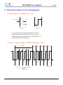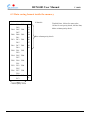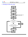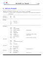
1
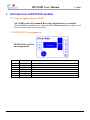
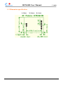
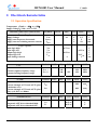
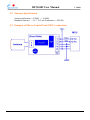
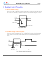
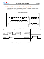
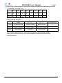
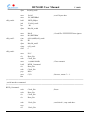
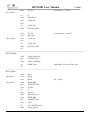
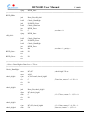
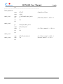
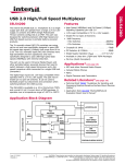
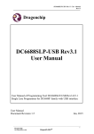
RFM-003 User Manual
V 1.00B
RFM-003
User Manual
2005/06/01
Ver. 1.00C
Sunion Electronic Corporation
11F, 123-7, Shine De Rd., San Chung City, Taipei 241, Taiwan, R.O.C.
TEL : +886-2-8512-1456 FAX : +886-2-8512-1457
http://www.sunion.com.tw/
1
RFM-003 User Manual
V 1.00B
─ Table of Contents ─
1. Introduction of RFM-003 module --------------------------------- 3
1-1 Type of application available ------------------------------------------------ 3
1-2 RFM-003 Pin assignments -------------------------------------------------- 3
1-3 Dimension specification ----------------------------------------------------- 4
2. Electrical characteristics --------------------------------------------- 5
2-1 Operation Specification ------------------------------------------------------ 5
2-2 Antenna Specifications ------------------------------------------------------- 6
2-3 Example of Micro-Control Unit (MCU) connection -------------------- 6
3. Reading Control Procedure ----------------------------------------- 7
3-1 Reset Module Timing -------------------------------------------------------- 7
3-2 Module Timing of Entering Data ------------------------------------------- 7
3-3 Transmit Command and receive Transponder Data ---------------------- 8
4. Data format of transponder --------------------------------------- 10
4-1 Description of Manchester Code ------------------------------------------ 10
4-2 Data format example of EM Manchester Code ------------------------- 10
4-3 Data saving format inside the memory ----------------------------------- 11
5. Reading procedure flow chart ------------------------------------ 12
6. Software example ---------------------------------------------------- 13
7. 125 KHz Antenna Manufacturing instructions ---------------- 18
Copyright 2003~2004 by SUNION Electronic Corporation
All right reserved.
2
RFM-003 User Manual
V 1.00B
1. Introduction of RFM-003 module
1-1 Type of application available
All 125KHz with ISO standard Read Only applications are available.
(For Read/Write application or other non-ISO standard applications please feel
free to contact your Sunion personal.)
1-2 RFM-003 Pin assignments
RFM-003 Pin position
and assignments:
Pin No.
Name
1
2
3
4
5
6
7
SCLK
DATA
GND
GND
VDD
ANT2
ANT1
Function
Serial clock input
Serial data In/Out
GND
GND
VDD
Antenna out 2
Antenna out 1
3
RFM-003 User Manual
V 1.00B
1-3 Dimension specification
L=25mm
W=20mm
H=11mm
4
RFM-003 User Manual
V 1.00B
2. Electrical characteristics
2.1 Operation Specification
Temperature:Tamb = - 40℃ to + 85℃
Supply Voltage:Vdd = 4.1V to 5.5V
PARAMETERS AND CONDITIONS
SYMBOL
NOTE
MIN.
TYP.
MAX.
UNIT
4.1
5
1
5
5.5
5
10
V
uA
mA
Power Supply
Supply Voltage
Supply current power down mode
Supply current excluding antenna current
VDD
IDDsleep
IDDon
Logic Signals
Input logic high
Input logic low
Output logic high
Output logic low
Input leakage current
PLL
Antenna capture frequency range
Antenna locking frequency range
NAME
Current through ANT1 and ANT2 pins.
Continuous wave
Current through ANT1 and ANT2 pins.
Duty cycle 20% ton<400ms
Antenna driver
Diagnostic ANT driver threshold high
Diagnostic ANT driver threshold low
VIH
VIL
VOH
VOL
0.7VDD
0.3VDD
0.9VDD
0.1VDD
1
-1
SYMBOL NOTE
V
V
V
V
uA
MIN.
TYP
MAX.
UNIT
100
100
125
150
150
KHz
KHz
MIN.
TYP
MAX.
UNIT
IANT
180
mAp
IANT
400
mAp
MAX.
UNIT
FANT_C
FANT_L
SYMBOL NOTE
SYMBOL NOTE
VH
VL
MIN.
TYP
0.5VDD
0.5VDD
V
V
5
RFM-003 User Manual
V 1.00B
2.2 Antenna Specification
Antenna inductance = 430uH ~ 460uH
Standard Antenna = 14 * 10.5 cm (Inductance = 425uH)
2.3 Example of Micro-Control Unit (MCU) connection
6
RFM-003 User Manual
V 1.00B
3. Reading Control Procedure
3-1 Reset Module Timing:
First, set the “CLK” to High, then “DTAT” to high; Wait for a while (At least 200ns) then set
the “CLK” to low, and also, set the “DATA” back to low (The minimum timing for ts is 50ns).
CLK
IN
ts: Min. 50ns
tres: Min. 200ns
Fig 1.Module Reset
3-2 Module Timing of Entering Data:
First, set the “DATA” to high, then set “CLK” to High; Wait for a while (At least 200ns) then
set the “CLK” to low, and also, set the “DATA” back to low (The minimum timing for ts is
50ns).
CLK
IN
tres
Min.200ns
ts:
Min. 50ns
“1”
“0”
Fig. 2. Module timing of entering data
7
RFM-003 User Manual
V 1.00B
3-3 Transmit Command and receive Transponder Data:
First, send the “Reset” command then send the “Command Structure Data”,
IN/OUT will receive the Transponder Data.
Send Command Structure
CLK 1
2
3
4
5
6
7
8
9
IN
1
2
3
4
5
6
7
8
Bit
OUT
9
Reset
CLK
DATA
10
Send Command Structure
Reset
Clock 1
Reset
…….
11
12
10
11
13
Manchester Code Data
Clock 13
High or Low
Manchester
Data
3.Command Program; Command transmit clock as above
8
RFM-003 User Manual
V 1.00B
Activate RF to read the card:
Bit1
Bit2
Bit3
Bit4
Bit5
Bit6
Bit7
Bit8
ON
0
1
0
0
1
0
0
0
OFF
0
0
0
0
1
0
0
0
Respond from Module:
Status
IF = “0”
IF = “1”
Correct Status
Bit9
Antenna Status
Correct Loading
Short Circuit
0
Bit10
Entering Status
Correct Signal
No-Enter-Signal
0
Bit11
PLL Status
Locked
Not Locked
0
Note: After transmit the No.9 CLK (CLK1~CLK9) and 8-bit command, send the
other 4 CLK (CLK10~CLK13), wait for the module to feedback the status of that
3-bit (bit9~bit11).
9
RFM-003 User Manual
V 1.00B
4. The data format of the Transponder
4-1 Description of Manchester Code:
T = 255 ~ 370 us*
Data is“0"
Data is“1"
“T” is a reference range, in practical, this figure will vary in
depends on different card manufacturers or even with same
manufacturer but different production lot. But in general, the “T”
should fall in the range as stated above.
4-2 Data format example of EM Manchester Code:
Head
Do0
Do1
Do2
Do3
P1
…..
1
1
1
….
…..
1
0
0
0
1
1
Parity check
9“1"Head values
10
RFM-003 User Manual
V 1.00B
4-3 Data saving format inside the memory
1 1 1 1 1 1 1 1 1
D00
D04
D08
D12
D16
D20
D24
D28
D32
D36
PC0
D01
D03
D05
D07
D09
D11
D13
D15
D17
D19
D02
D21
D23
D25
D27
D29
D31
D33
D35
D37
D39
D22
PC1
PC3
PC2
D06
D10
D14
D18
P0
P1
P2
P3
P4
P5
P6
P7
P8
9 Start bit
Total 64 bites, 9 bites for start value,
10 bits for row parity check, 40 bits data,
4bites column parity check.
Bits column parity check.
P9
D26
D30
D34
D38
0
Column parity check
11
RFM-003 User Manual
V 1.00B
5. Reading procedure flow chart
Reset
Send Command
01001000
Send 3 Clocks to
Receive Status Bits
Send Entering
Data
Module responds “DATA” and
“CLOCK” back to MCU
Delay 20 ms
No
Is a “Head” been
received within
100ms?
Yes
Receive again
Receiving card ID and
parity check code, and
verify it
Yes
No
Send Command
00001000
END
12
RFM-003 User Manual
V 1.00B
6. Software Example
;===========================================================================
; RFM003.ASM; Software example for MCU 8051. Frequency=11.0592Mhz
; T0CountL = is a “Down Counter”, one count down is about 0.4ms per count, then next is generated by
“T0 Interrupt”.
;===========================================================================
Data_Pin
Bit
P3.3
Clock_Pin
Bit
P3.2
;===========================================================================
RFIDInit:
clr
Data_Pin
setb
Clock_Pin
ret
;===========================================================================
RFIDRead:
push
DR2
mov
A,#01001000B
lcall
RFID_Command
; Start transmit
setb
Data_Pin
mov
A,T0CountL
add
A,#205
; (255-205) x 0.4 ms = 20 ms.
cjne
A,T0CountL,$
; delay 20 ms.
mov
R2,T0CountL
inc
R2
; (255-1) x 0.4 ms = 101 ms.
rfid_read1:
mov
A,R2
cjne
A,T0CountL,rfid_read2
clr
C
sjmp
rfid_read6
rfid_read2:
lcall
RFID_RHead
jnb
F0,rfid_read1
mov
R4,#8
; read 8 bits data = 1.
rfid_read3:
call
RFID_RBit
jnb
F0,rfid_read1
jnc
rfid_read1
; jmp if bit = 0.
13
RFM-003 User Manual
rfid_read4:
rfid_read5:
V 1.00B
djnz
R4,rfid_read3
mov
mov
lcall
jnb
inc
djnz
R4,#5
R1,#RFIDBuf
RFID_RByte
F0,rfid_read1
R1
R4,rfid_read4
; read 5 bytes data.
mov
mov
cjne
inc
djnz
sjmp
setb
R4,#5
R1,#RFIDBuf
@R1,#0ffH,rfid_read6
R1
R4,rfid_read5
rfid_read1
C
; if card ID= FFFFFFFFFF then ignore.
rfid_read6:
mov
F0,C
clr
Data_Pin
setb
Clock_Pin
mov
A,#00001000B
; Close transmit
lcall
RFID_Command
clr
Data_Pin
setb
Clock_Pin
pop
DR2
mov
C,F0
; Success, return C = 1.
Ret
;===========================================================================
; serial interface command.
;===========================================================================
RFID_Command:
setb
Clock_Pin
; Reset.
setb
Data_Pin
clr
Clock_Pin
clr
Data_Pin
setb
nop
clr
Clock_Pin
; send clock 1, stop send data..
Clock_Pin
14
RFM-003 User Manual
mov
R7,#8
rlc
mov
setb
nop
clr
djnz
A
Data_Pin,C
Clock_Pin
V 1.00B
; send clock 2 ~ clock 9.
rfid_comd1:
Clock_Pin
R7,rfid_comd1
mov
R7,#4
; read clock 10 ~ clock 13.
setb
Data_Pin
rfid_comd2:
setb
Clock_Pin
nop
clr
Clock_Pin
djnz
R7,rfid_comd2
ret
;===========================================================================
RFID_RHead:
lcall
Check_DataLow
jnb
F0,RFID_Error
lcall
Check_DataHigh
jnc
RFID_Error
; jmp High Too short or Time Out.
ret
;----------------------------------------------------------------------------------RFID_RByte:
mov
B,#2
rfid_rbyte1:
mov
R5,#4
mov
R6,#0
; R6 = parity.
rfid_rbyte2:
lcall
RFID_RBit
jnb
F0,RFID_Error
mov
A,@R1
rlc
A
mov
@R1,A
djnz
R5,rfid_rbyte2
lcall
RFID_RBit
jnb
F0,RFID_Error
mov
A,R6
jb
ACC.0,RFID_Error
djnz
B,rfid_rbyte1
15
RFM-003 User Manual
V 1.00B
sjmp
RFID_Succ
;===========================================================================
RFID_RBit:
jnb
Data_Pin,rfid_rbit1
lcall
Check_DataHigh
jnb
F0,RFID_Error
lcall
Check_DataLow
jnc
RFID_Error
clr
C
; set data = 0.
sjmp
RFID_Succ
rfid_rbit1:
lcall
Check_DataLow
jnb
F0,RFID_Error
lcall
Check_DataHigh
jnc
RFID_Error
inc
R6
; set data = 1, parity++.
RFID_Succ:
setb
F0
ret
RFID_Error:
clr
F0
ret
;===========================================================================
; 130us < Data High or Data Low < 370 us
;===========================================================================
Check_DataHigh:
mov
R7,#57
; check high 370 us.
mov
A,R2
check_high1:
cjne
A,T0CountL,check_high2
clr
C
; Time Out, return C = 0. F0 = 0.
clr
F0
ret
check_high2:
jnb
Data_Pin,check_high3
djnz
R7,check_high1
setb
C
; if > 370 us, return C = 1, F0 = 0.
clr
F0
ret
check_high3:
cjne
R7,#35,check_high4
; if < 130us, return C = 0, F0 = 1.
check_high4:
setb
F0
; Success, return C = 1, F0 = 1.
16
RFM-003 User Manual
V 1.00B
ret
;---------------------------------------------------------------------------------Check_DataLow:
mov
R7,#57
; Check Low 370 us.
mov
A,R2
check_low1:
cjne
A,T0CountL,check_low2
clr
C
; Time Out, return C = 0. F0 = 0.
clr
F0
ret
check_low2:
jb
Data_Pin,check_low3
djnz
R7,check_low1
setb
C
; if > 370 us, return C = 1, F0 = 0.
clr
F0
ret
check_low3:
cjne
R7,#35,check_low4
; if < 130us, return C = 0, F0 = 1.
check_low4:
setb
F0
; Success, return C = 1, F0 = 1.
ret
17
RFM-003 User Manual
V 1.00B
1 125 KHz Antenna Manufacturing instructions
1. Measure or examine the size and shape of the mechanism you want to put the antenna to decide of how
big and what will be the shape of your antenna*.
2. Use the size and shape you measured for antenna to build up the tooling. You can use any kind of
materials for that antenna tooling except metal; the only thing you have to worry about is would it be
able to sustain the force when you wind the wire around? Also, after finished, the antenna should be
able to pull easily out of that tooling.
3. Choose enamel-insulated wire with appropriate diameter, general speaking a wire with 0.5mm diameter
should be ok; Also, to optimize the inductance and Q value, you should use thicker wire for bigger
antenna (it also will decrease the amount of circles); the thinner wire for smaller antenna (the amount
of circles, in the other hand, will increased); We suggest you make more circles on first trying, it would
be very helpful when performing adjustment hereafter.
4. Winding the wires on that tooling circle by circle then use inductance meter to measure the inductance
value, the right value is around 425 mH**. (Reduce circles if the value greater then 425 mH)
5. Use tape or other suitable things to fasten the antenna you have just made to prevent any possible
distortion when adjusting or pulling out of the tooling.
6. Connect antenna to reader for testing; First, connect an oscilloscope’s probe to a circuit with bigger
inductance (like the relay circuit) then approaching it to antenna (fig.1), now, you should be able to see
a wave pattern shown on your oscilloscope like fig.2.
7. Hold that position of both probe and circuit on it then try to slowly decrease or increase the amount of
circles and also keep an eye on the scope, stop when reach the maximum amplitude. ***
8. Test the reader’s reading range with transponder (tag) then repeat step 7th for fine tuning until you get
the maximum reader range.
9. Pull the antenna out from tooling, there we are~~!
*. According to our experience, the antenna’s shape will have a great influence in reading; generally, with the same inductance the
square type will have better range in compare with circle type and full square type is better then rectangle.
**. We suggests using the method of circle by circle to wind the wire instead of crisscross, because the effect is almost the same but
more easily to adjust with circle by circle.
***. Sometimes the maximum amplitude doesn’t mean the best range, it is because even we have the best transmitting, but however,
the sensitive of receiving is decreased (we are using same antenna for both transmit and receive, that why!), therefore, we need
to repeat step 8th to make sure we are in the best configuration.
Fig.1
Fig.2
18