1
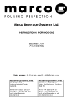
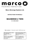
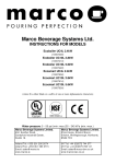
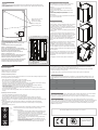
MOUNTING :
IMPORTANT:
WARNING: THE BOILER MUST BE MOUNTED ON A SOLID CONCRETE WALL BY A QUALIFIED FITTER.
MARCO DOES NOT ACCEPT RESPONSIBILITY FOR THE SAFETY OF ANY MACHINE NOT INSTALLED ON
A SOLID CONCRETE WALL.
ACCESS TO INTERNAL COMPONENTS:
Any maintenance work on any Ecoboiler product should
ONLY be conducted by a trained service engineer.
Removal
1.Disconnect the machine from the electrical supply
2.Allow to cool sufficiently.
3.The removable side panels are fixed at the top of the
machine.
4. Removewith a Philips head screwdriver.
5.Remove the panels in an upward and outward motion.
Reassembly
To re-attach the front panels, complete the removal actions in
steps 4 & 5 in reverse order.
Mark points on the wall to be
drilled for anchor plugs.
(See reverse for footprint)
Primary mounting points.
Optional anchoring points.
SAFETY:
•This appliance must be earthed.
•Risk of flooding. The hose supplied with this unit is non-toxic
food quality tested to 190psi. However, a hose is not a
permanent connection. It is, therefore, advisable to switch off
boiler and close the stopcock valve when boiler is not in use,
e.g. overnight, weekends etc.
•Risk of scalding. Beware of accidentally operating the water
draw off tap.
B
•The utmost care has been taken in the manufacture and
testing of this unit. Failure to install, maintain and / or operate
this boiler according to the manufacturer’s instructions may
result in conditions that can cause injury or damage to
property. If in any doubt about the serviceability of the boiler
always contact the manufacturer or your own supplier for
advice.
A
• Insert anchor plugs into the drilled wall.
(See mounting footprint on reverse)
• Remove side panels (two screws on the top of the
machine)
• Plumb machine to mains using either option:
•This appliance is not intended for use by persons (including
children) with reduced physical, sensory, or mental
capabilities, or lack of experience and knowledge, unless
they have been given supervision or instruction concerning
use of the appliance by a person responsible for their safety.
Option 1: Plumbing from bottom.
Remove the cover plate at the base of the machine.
Feed the inlet hose through the square hole at the base of
the machine. (See point A on figure above)
Attach the non-angled hose end to the solenoid.
•Children should be supervised to ensure that they do not play
with the appliance
•In the event any wires are damaged, such wires can only be
replaced by experts or professional after service staff from the
manufacturer, after service department or similar function
departments
Option 2: Plumbing from rear.
Feed the inlet hose through the rectangular hole at the
rear of the machine. (See point B on figure above)
Attach the angled hose end to the solenoid.
• Ensure the overflow hose lies outside of the machine.
• Bolt the machine securely to the wall using bolts.
• Replace the side panels and secure in place.
•The appliance must be securely fitted to a suitable wall.
Machine on wall
INSTALLATION DETAILS:
Electrical installation:
•Electrical specification: 2.4kW-230V-50Hz
•Suitable fusing for a 2.4-3 KW circuit.
•Ensure the machine is fully earthed.
Towards the end of the boilers operating period for a given day, switch the machine to ECO Mode.
Whilst maintaining water at 96oC, the machine tank will slowly drop to half full, where it will remain.
At the end of the machines operating period it should be turned ‘off’.
During the ‘off’ period as there is less water in the tank there will be less energy lost to the surrounding
environment resulting in an energy saving.
To disable simply press the ‘ECO Mode’ button again so that the leaf symbol is not illuminated
Plumbing installation procedure:
T RO UBL E S HO O T ING :
Note: Marco recommend that this machine be positioned over a counter with a drainage facility. Marco cannot
be held responsible for any flood damages.
The Ready/Status light signals various errors or problems. A cycle of red flashes indicates an error. The
number of flashes in a cycle corresponds to the symptom in the table below: St at u s/ Di ag n ost i c lig ht
g u id e:
• Mains water pressure required (limits): 5-50psi (35-345kPa)
• Fit a stop Valve on a cold water line and attach a 3/4" BSP male fitting,
(E.g. 3/4" x 1/2" 311 or washing machine type stop valve).
• Connect the hose to the inlet valve of the boiler (again 3/4" BSP). The orientation of the tail piece will vary
depending on whether machine is plumbed at the rear or at the underside.
• Connect the other end of the inlet hose to the stop valve fitting. Make sure that the pre-attached
sealing washer is fitted.
• If the overflow tubing is pumped it must be pumped with a tundish device.
If the overflow tubing it not pumped the overflow tube should stick out of the base of the machine.
• Turn on water and check for leaks.
• Turn on the water to flush any impurities, dust etc from the inlet hose and water pipe. Allow several litres
through.
Operating boiler for the first time:
•
•
•
•
Check that all installation procedures have been carried out.
Ensure water valve is on and there is power to the appliance.
The “Ready/Status” light will cycle two red flashes while the machine is filling to the safe level.
After this amount of water has heated to about 96ºC the boiler will draw more water in until the
temperature drops by 1 or 2 degrees. The boiler will then heat again.This heat fill cycle continues until the
boiler is full.
• Whilst the machine is above the safe level and filling, the “Ready/Status” light will remain blank.
• The “Ready/Status” light will glow green when the machine is both full and up to normal operating
temperature.
• The boiler is now ready for use.
POWER
BUTTON
No o f
fla sh e s
S ymptom
Ac t ion req ui r ed
Water level below elements. Normal when
machine first fills.
Temperature sensor failure (o/c)
Check water pressure , if this is OK then call service
agent.
Call service agent
4
Water not heating
Call service agent
5
Temperature sensor failure (s/c)
Call service agent
6
Machine not filling
Check water pressure, if OK then call service agent.
2
3
CLEANING:
The exterior of these machines may be cleaned with a damp cloth and a light detergent. Do not use abrasive
cloths or creams, as this will spoil the finish of the machine. Do not use a water jet or spray.
NB: Beware of accidentally operating the draw off tap or push button when cleaning the front of the machine.
LIMESCALE:
In common with all water boiler manufacturers, service calls resulting from limescale are not covered by
warranty. Fitting a scale reducer is recommended, especially in hard water areas. This can reduce the build-up
of scale but may not stop it altogether. The frequency that descaling is required depends on the local water
supply; hard water areas need more attention. Descaling of the machine should ideally be carried out by
qualified service personnel.
NOTE: Because the boiler is electronically controlled no priming is necessary.
The element cannot switch on until a safe level of water is reached.
ECO Mode Operation:
•All ECO Boilers use high grade insulation and it is applied to give a
significant energy usage improvement over a standard water boiler.
•The ECO Boiler incorporates a ½ tank ‘ECO mode’ function.
READY/
•To enable the ‘ECO Mode’ press the button located below the ‘Ready’
STATUS
indicator so that the leaf symbol illuminates green.
INDICATOR
•This mode saves energy by minimising the energy wasted during
machine down-time.
•NOTE: The ECO mode is most effective in installations where the
machine has a regular ‘off’ period.
•To achieve the most benefit from the energy saving ‘ECO Mode’ on
ECO MODE
your ECO boiler unit the following method should be employed:
BUTTON
Ecoboiler Wallmount Footprint on reverse.
MARCO is an ISO9001:2000
Registered Company
280mm
Primary mounting points.
Primary mounting points.
280mm
INSTALLATION INSTRUCTIONS
Ecoboiler WMT3 (p/n1000670)
Ecoboiler WMT5 (p/n 1000671)
Ecoboiler WMPB3(p/n 1000675)
Ecoboiler WMPB5 (p/n 1000676)
Mains pass through this area if
plumbed from the rear.
(
Ecoboiler Wallmount
Footprint
1:1
Water pressure : 5 - 50 psi (min.-max.)35 - 345 kPa (min.-max.)
)
Marco Beverage Systems Limited.
63d Heather Road,
Sandyford Industrial Estate,
Dublin 18.
Inlet connection passes
through this area if
plumbed from the rear.
Ireland Tel: +353 (0)1 295 2674
Ireland Fax: +353 (0)1 295 3715
email: [email protected]
www.marco.ie
Marco Beverage Systems Limited.
Shire House, Strixton Manor,
Strixton, Wellingborough, Northants,
NN29 7PA
UK Tel: +44 (0)2072 744 577
UK Fax: +44 (0)2079 788 141
email: [email protected]
www.marco-bev.co.uk